
Trends in Combat Design
Howard Rush
Editor's Note: Like many modelers with different interests, your editor has — we now should say "had" — an oversimplified picture of what makes the combat flier tick. Mr. Rush's article is a long overdue exposition of the serious and scientific side of an impressive event. We urge everyone to read this feature — it is an eye-opener. And for Combat people, it is a perceptive, valuable report on the state of the art.
The dominant trend
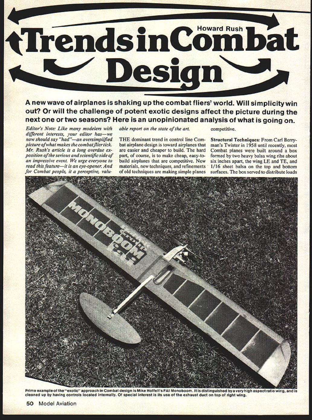
The dominant trend in control-line Combat airplane design is toward airplanes that are easier and cheaper to build. The hard part, of course, is to make cheap, easy-to-build airplanes that are competitive. New materials, new techniques, and refinements of old techniques are making simple planes competitive.
Structural Techniques
From Carl Berryman's Twister in 1958 until recently, most Combat planes were built around a box formed by two heavy balsa wing ribs about six inches apart, the wing LE and TE, and 1/16" sheet balsa on the top and bottom surfaces. The box served to distribute loads from the engine, which was mounted on beams attached to more structure in the box's center. The bellcrank was supported by the rib on the left side of the box and a metal fuel tank was nestled between the engine mounts and the rib on the right side of the box. The ribs also carried loads from two tail booms, which supported a stabilator.
About 12 years ago, pen-bladder and baby-pacifier fuel systems replaced metal tanks. Then, inspired by John Kilsdonk, builders began attaching the bellcrank mount to the engine mounts. Clever people in Detroit and Cincinnati saw that the box structure, which now served only to carry engine and tail-boom loads, could be replaced by a structurally more efficient single fuselage.
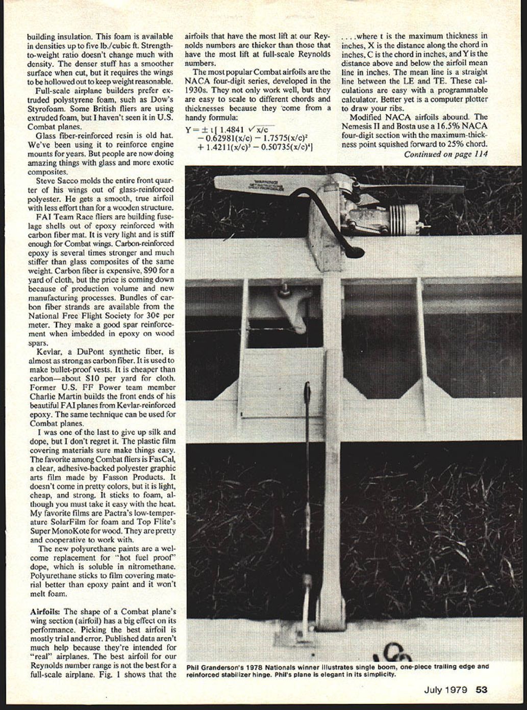
Although the single-boom structure took ten years to catch on, it has been adopted almost universally by U.S. Combat fliers in the last year or so. Builders have come up with structures that are simple and light, yet strong enough to withstand the rigors of Combat.
Lots of reinforcement is required at the stabilator hinge to keep the tail from breaking off when it snags the grass or the launcher's leg. Hinges are usually music wire and brass tubing, reinforced with plywood, cloth, and epoxy. I like Phil Cartier's method — a Rocket City nylon strip hinge with the front half imbedded in a 1/2" x 3" plywood stabilator.
Another time-saving construction trick is the one-piece TE. This method uses one 1/8" TE sheet, rather than two sheets of 1/16" wood with a tedious-to-cut chamfered joint. The one-piece TE is sharpened at the rear and fits into slots in the ribs. Gussets make the rib–TE joints sturdy. Assembly is much easier than the old way. This type of construction is well-suited for airfoils like Wortmann's, which are concave and quite thin at the TE. The one-piece TE is warp-prone, so use hard wood.
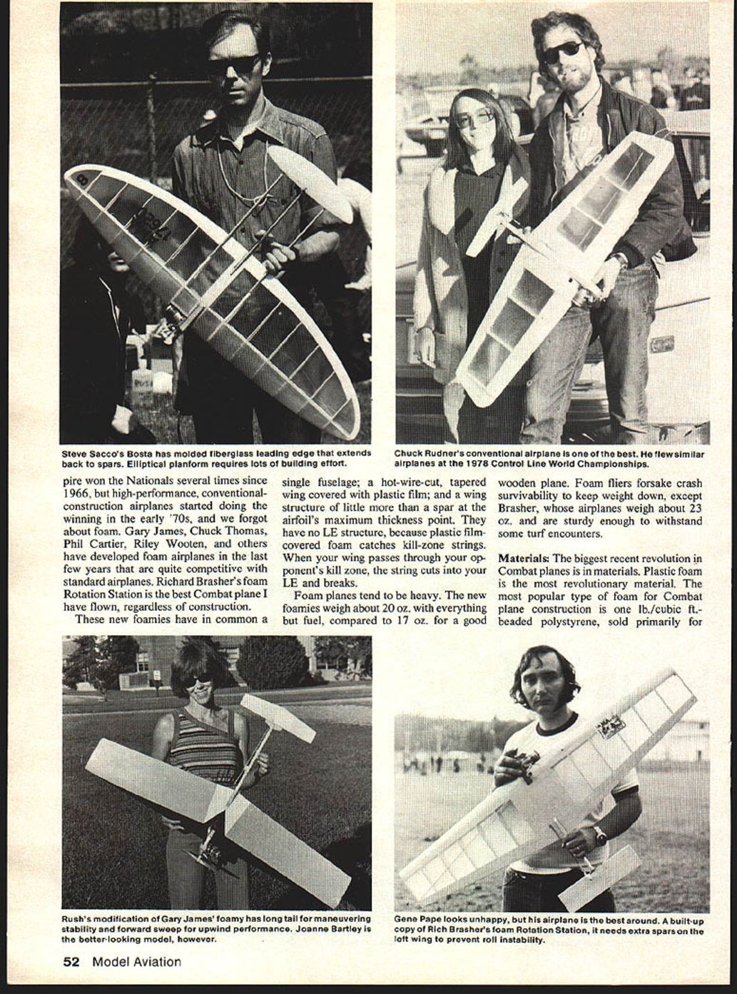
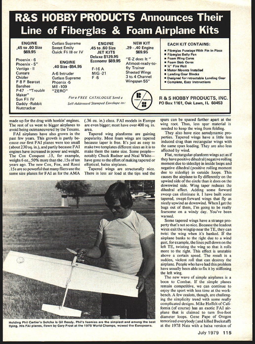
The single-boom concept and plastic-film covering materials have made plastic-foam airplanes practical. Foam airplanes have been around a long time. They've won the Nationals several times since 1966, but high-performance, conventional-construction airplanes started doing the winning in the early '70s, and we forgot about foam. Gary James, Chuck Thomas, Phil Cartier, Riley Wooten, and others have developed foam airplanes in the last few years that are quite competitive with standard airplanes. Richard Brasher's foam Rotation Station is the best Combat plane I have flown, regardless of construction.
These new foamies have in common a single fuselage; a hot-wire-cut, tapered wing covered with plastic film; and a wing structure of little more than a spar at the airfoil's maximum thickness point. They have no LE structure, because plastic-film-covered foam catches kill-zone strings. When your wing passes through your opponent's kill zone, the string cuts into your LE and breaks.
Foam planes tend to be heavy. The new foamies weigh about 20 oz. with everything but fuel, compared to 17 oz. for a good wooden plane. Foam fliers forsake crash survivability to keep weight down, except Brasher, whose airplanes weigh about 23 oz. and are sturdy enough to withstand some turf encounters.
Materials
The biggest recent revolution in Combat planes is in materials. Plastic foam is the most revolutionary material. The most popular type of foam for Combat plane construction is one lb./cubic ft.–beaded polystyrene, sold primarily for insulation. This foam is available in densities up to five lb./cubic ft. Strength-to-weight ratio doesn't change much with density. The denser stuff has a smoother surface when cut, but it requires the wings to be hollowed out to keep weight reasonable.
Full-scale airplane builders prefer extruded polystyrene foam, such as Dow's Styrofoam. Some British fliers are using extruded foam, but I haven't seen it in U.S. Combat planes.
Glass-fiber-reinforced resin is old hat. We've been using it to reinforce engine mounts for years. But people are now doing amazing things with glass and more exotic composites.
Steve Sacco molds the entire front quarter of his wings out of glass-reinforced polyester. He gets a smooth, true airfoil with less effort than for a wooden structure.
FAI Team Race fliers are building fuselage shells out of epoxy reinforced with carbon-fiber mat. It is very light and is stiff enough for Combat wings. Carbon-reinforced epoxy is several times stronger and much stiffer than glass composites of the same weight. Carbon fiber is expensive—about $90 for a yard of cloth—but the price is coming down because of production volume and new manufacturing processes. Bundles of carbon-fiber strands are available from the National Free Flight Society for 30¢ per meter. They make a good spar reinforcement when imbedded in epoxy on wood spars.
Kevlar, a DuPont synthetic fiber, is almost as strong as carbon fiber. It is used to make bullet-proof vests. It is cheaper than carbon—about $10 per yard for cloth. Former U.S. FF Power team member Charlie Martin builds the front ends of his beautiful FAI planes from Kevlar-reinforced epoxy. The same technique can be used for Combat planes.
I was one of the last to give up silk and dope, but I don't regret it. The plastic-film covering materials sure make things easy. The favorite among Combat fliers is FasCal, a clear, adhesive-backed polyester graphic-arts film made by Fasson Products. It doesn't come in pretty colors, but it is light, cheap, and strong. It sticks to foam, although you must take it easy with the heat. My favorite films are Pactra's low-temperature SolarFilm for foam and Top Flite's Super MonoKote for wood. They are pretty and cooperative to work with.
The new polyurethane paints are a welcome replacement for "hot fuel proof" dope, which is soluble in nitromethane. Polyurethane sticks to film covering material better than epoxy paint and it won't melt foam.
- Key materials and coverings:
- Beaded polystyrene foam (1 lb./cu ft and up)
- Extruded polystyrene foam (e.g., Styrofoam)
- Glass-fiber-reinforced polyester/epoxy
- Carbon-fiber reinforcements and mats
- Kevlar-reinforced epoxy
- FasCal, SolarFilm, Super MonoKote (film coverings)
- Polyurethane paints
Airfoils
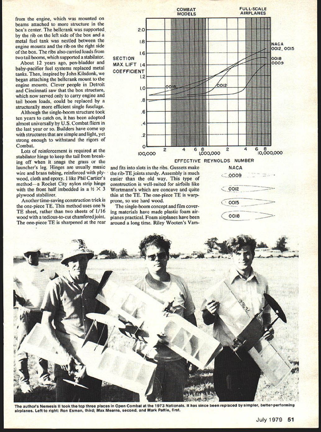
The shape of a Combat plane's wing section (airfoil) has a big effect on its performance. Picking the best airfoil is mostly trial and error. Published data aren't much help because they're intended for "real" airplanes. The best airfoil for our Reynolds-number range is not the best for a full-scale airplane. The airfoils that have the most lift at our Reynolds numbers are thicker than those that have the most lift at full-scale Reynolds numbers.
The most popular Combat airfoils are the NACA four-digit series, developed in the 1930s. They not only work well, but they are easy to scale to different chords and thicknesses because they come from a handy formula:
Y = ± t [1.4841 sqrt(x/c) - 0.62981(x/c) - 1.7575(x/c)^2 + 1.4211(x/c)^3 - 0.50735(x/c)^4]
where t is the maximum thickness in inches, x is the distance along the chord in inches, c is the chord in inches, and Y is the distance above and below the airfoil mean line in inches. The mean line is a straight line between the LE and TE. These calculations are easy with a programmable calculator. Better yet is a computer plotter to draw your ribs.
Modified NACA airfoils abound. The Nemesis II and Bosta use a 16.5% NACA four-digit section with the maximum-thickness point moved forward to 25% chord. Gary James and Steve Sacco have modified the NACA formula to change such things as the LE radius and TE angle.
The best airfoil to use depends also on the wing surface bumpiness. Surface imperfections near the LE really degrade the Nemesis II airfoil's performance, but the foamies get away with their bumpy surfaces by using really blunt LEs. I'm using a Gary James–modified NACA airfoil with a fat LE on my foamy and it works great.
New airfoil design techniques have been developed in the last few years that may make airfoil design scientific and spoil our fun. These techniques consist of determining what pressure distribution you want and then calculating the shape that gives it to you.
F.X. Wortmann, at the University of Stuttgart, has designed some of these new-fangled airfoils for full-scale sailplane tail surfaces that operate at the same Reynolds numbers and design conditions as Combat models. His wind-tunnel data show improvement over the old NACA airfoils, but Combat fliers have shown little interest in trying the new sections—probably because they look so different. They have pretty sharp LEs and are concave near the TE. Want to be the first kid on your block to try one? They are in Stuttgarter Profilkatalog I, by D. Althaus, published by the Institute für Aero- und Gasdynamik, University of Stuttgart, Germany, 1972.
Configuration: airplanes are bigger now
There are several reasons why.
Combat planes must turn tight, fast loops. The minimum loop diameter an airplane can turn is proportional to its wing area (if other factors don't change). Area loading is the ratio of weight to wing area. The speed an airplane can maintain in consecutive maneuvers depends on its induced drag. For a given loop size and speed, induced drag is proportional to the square of the span loading. Span loading is the ratio of weight to wingspan.
Foamies need lots of wing area and span to make up for the foam's weight disadvantage. Because engine, fuel, and line weight are constant, you get a lower area loading and span loading by going to a bigger, longer wing. AMA-class foamies typically have 42" to 48" spans and 360 to 400 sq. in. areas, compared to 39" spans and 320 to 360 sq. in. areas for conventional planes.
Conventional-construction airplanes have practical wingspan limits. Balsa comes in 36" lengths. More span means buying more-expensive 48" wood. It is also harder to keep warps out of longer wings. Sherwood Buckstaff and his Texan colleagues kept to 36" span, but increased chord to 10"—an inch more than the standard planes of the time—and gained an area-loading advantage over us. They paid for the area with increased drag, but they made up for the drag with honkin' engines. The rest of us went to bigger airplanes to avoid being outmaneuvered by the Texans.
FAI airplanes have also grown in the past few years. This growth is partly because our first FAI planes were too small (about 230 sq. in.), and partly because FAI engines have increased in power and weight. The Cox Conquest .15, for example, weighs 6 oz., 50% more than the .15s of ten years ago. The new Cox, Fox, and Rossi .15s are so powerful that many fliers use the same size planes for FAI as for the AMA (.36 cu. in.) class. FAI models in Europe are even bigger; most have over 400 sq. in. area.
Tapered wing planforms are gaining popularity. Most foam wings are tapered because taper is free. It's just as easy to make two templates different sizes as it is to make them the same size. Some people—notably Chuck Rudner and Neal White—have gone to the effort of making tapered or elliptical balsa airplanes.
Tapered wings are structurally nice. There is less air load at the tips and the spars can be spaced farther apart at the wing root. Thus, less spar material is needed to keep the wing from folding.
They also have nice aerodynamic properties. Tapered wings have a little less induced drag than rectangular wings with the same span loading. They are also less affected by wind.
Flat, rectangular-planform wings act as if they have positive dihedral (negative rolling moment due to sideslip) in inside loops and negative dihedral (positive rolling moment due to sideslip) in outside loops. This causes the airplane to fly differently on the upwind side of the circle than it does on the downwind side. Wing taper reduces the dihedral effect. Adding some forward sweep can eliminate it. I have built some tapered, swept-forward wings that fly as nicely upwind as downwind. When I get the bugs out of them, I'm going to be really fearsome on a windy day. You've been warned.
Some tapered wings have a strange property that's not so nice. Because the loadout wires exit the wingtip near the TE, they can twist the wing when it's banked. If the airplane banks to the right due to a wind gust, for example, the lines pull down on the left TE, twisting the wing so that it rolls more to the right. This effect is unstable above a certain speed. The result is a sudden, violent roll that can destroy the airplane. People who have had this problem have usually been able to fix it by stiffening the left wing.
The new wave of simple airplanes is a boon to Combat. If the simple planes remain competitive, we can continue to enjoy the sport with less time at the workbench. A few zealots, though, are challenging the simplicity trend with some really complicated designs. Mike Hoffelt of California (of course) has an exotic FAI airplane that is claimed to turn five-foot-diameter loops. Gene Pape of Oregon terrorized everybody (and killed Buckstaff) at the 1978 Nats with a balsa version of Brasher's Rotation Station.
Are the exotic planes worth the effort? The next season or two will determine which way Combat design will go.
Transcribed from original scans by AI. Minor OCR errors may remain.

