
Truant
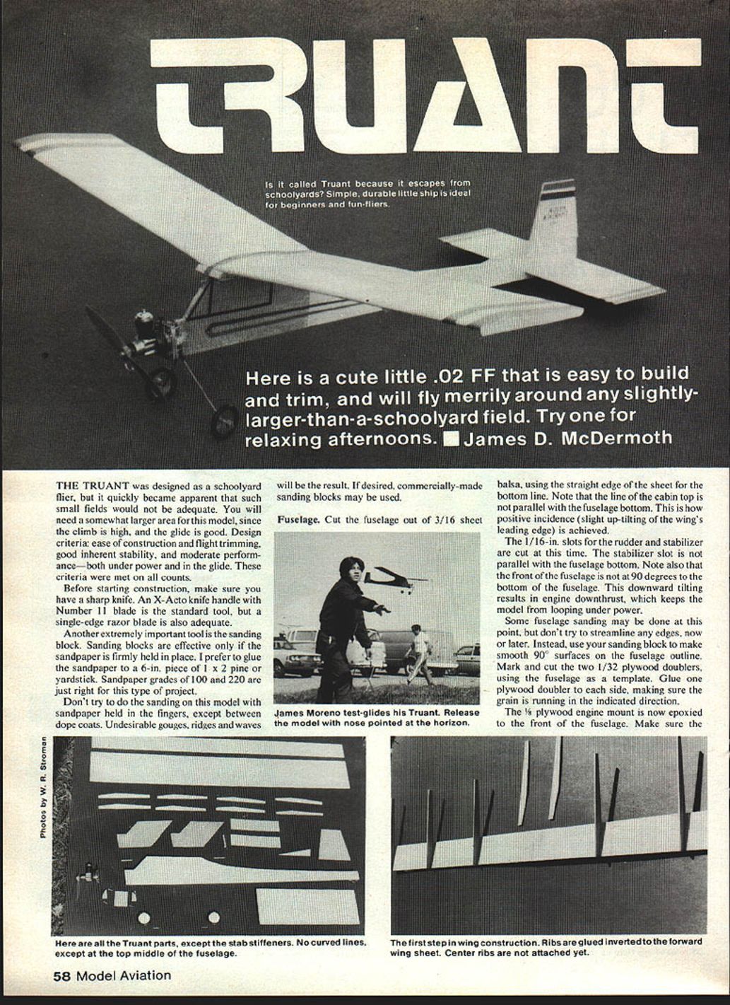
The Truant was designed as a schoolyard flyer, but it quickly became apparent that such small fields would not be adequate. You will need a somewhat larger area for this model, since the climb is high and the glide is good. Design criteria were ease of construction and flight trimming, good inherent stability, and moderate performance — both under power and in the glide. These criteria were met on all counts.
Before starting construction, make sure you have a sharp knife. An X-Acto knife handle with a No. 11 blade is the standard tool, but a single-edge razor blade is also adequate.
Another extremely important tool is the sanding block. Sanding blocks are effective only if the sandpaper is firmly held in place. It is convenient to glue the sandpaper to a 6-in. piece of 1 x 2 pine or a yardstick. Sandpaper grades of 100 and 220 are just right for this type of project.
Don't try to do the sanding on this model with sandpaper held in the fingers, except between dope coats. Undesirable gouges, ridges and waves will result. If desired, commercially made sanding blocks may be used.
Fuselage
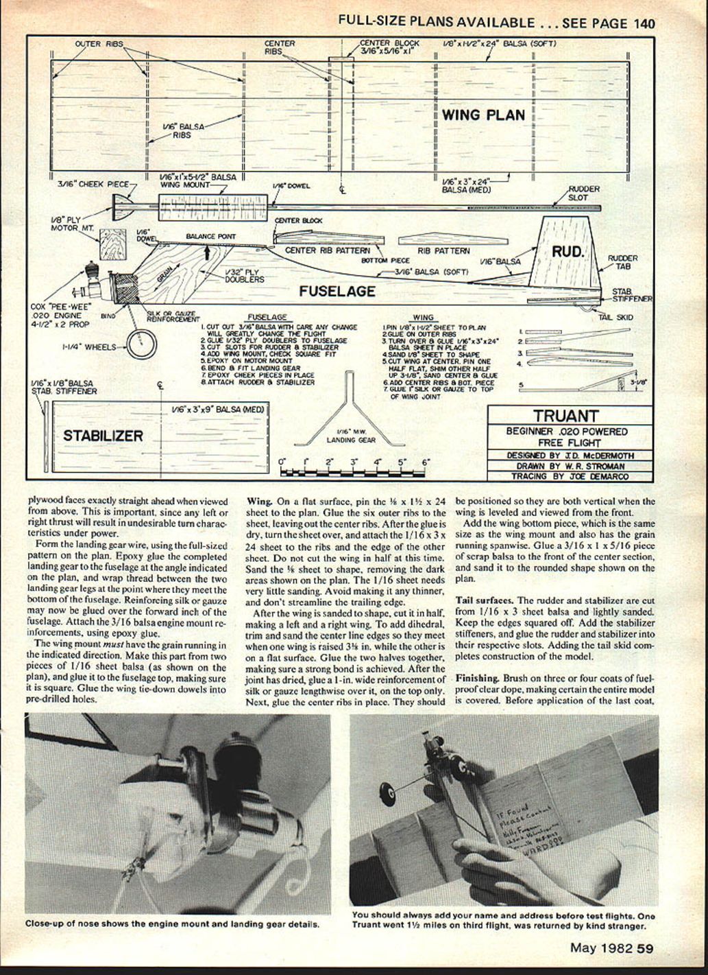
Cut the fuselage out of 3/16" sheet balsa, using the straight edge of the sheet for the bottom line. Note that the line of the cabin top is not parallel with the fuselage bottom. This is how positive incidence (a slight up-tilt of the wing's leading edge) is achieved.
Cut the 1/16" slots for the rudder and stabilizer at this time. The stabilizer slot is not parallel with the fuselage bottom. Note also that the front of the fuselage is not at 90° to the bottom of the fuselage. This downward tilting results in engine downthrust, which keeps the model from looping under power.
Some fuselage sanding may be done at this point, but don't try to streamline any edges now or later. Instead, use your sanding block to make smooth 90° surfaces on the fuselage outline. Mark and cut the two 1/32" plywood doublers, using the fuselage as a template. Glue one plywood doubler to each side, making sure the grain is running in the indicated direction.
Epoxy the 1/8" plywood engine mount to the front of the fuselage. Make sure the plywood faces exactly straight ahead when viewed from above; this is important since left-right thrust will result in undesirable turn characteristics under power.
Form the landing gear wire using the full-size pattern on the plan. Epoxy the completed landing gear to the fuselage at the angle indicated on the plan; wrap thread between the two landing gear legs at the point they meet the bottom fuselage. Reinforcing silk gauze may now be glued over the forward 1" of the fuselage.
Attach 3/16" balsa engine mount reinforcements using epoxy glue. The wing mount must have the grain running in the indicated direction. Make the part from two pieces of 1/16" sheet balsa shown on the plan; glue to the fuselage top, making sure it is square. Glue wing tie-down dowels in pre-drilled holes.
Wing
On a flat surface, pin the 1/16" x 1-1/2" x 24" sheet to the plan. Glue the six outer ribs to the sheet, leaving out the center ribs. After the glue is dry, turn the sheet over and attach the 1/16" x 3" x 24" sheet to the ribs and to the edge of the other sheet. Do not cut the wing in half at this time.
Sand the 1/16" sheet to shape, removing the dark areas shown on the plan. The 1/16" sheet needs very little sanding. Avoid making it any thinner, and don't streamline the trailing edge.
After the wing is sanded to shape, cut it in half, making a left and a right wing. To add dihedral, trim and sand the center-line edges so they meet when one wing is raised 3/8" while the other is on a flat surface. Glue the two halves together, making sure a strong bond is achieved. After the joint has dried, glue a 1-in.-wide reinforcement of silk or gauze lengthwise over it, on the top only.
Next, glue the center ribs in place. They should be positioned so they are both vertical when the wing is leveled and viewed from the front. Add the wing bottom piece, which is the same size as the wing mount and also has the grain running spanwise. Glue a 3/16" x 1" x 5/16" piece of scrap balsa to the front of the center section, and sand it to the rounded shape shown on the plan.
Tail surfaces
Cut the rudder and stabilizer from 1/16" x 3" sheet balsa and lightly sand them. Keep the edges squared off. Add the stabilizer stiffeners, and glue the rudder and stabilizer into their respective slots. Adding the tail skid completes construction of the model.
Finishing
Brush on three or four coats of fuel-proof clear dope, making certain the entire model is covered. Before application of the last coat, write your name, address and phone number on the model. This will greatly improve your chances of getting the model back if it is lost on a long flight.
A light sanding between coats, with very fine sandpaper held in the fingers, will produce a smooth finish. To add numbers, stripes or other decorations as desired, use colored dope of the same type and brand as your clear dope, or colored tissue applied with clear dope. Don't use any enamel paints, since either the clear dope or the fuel will cause big problems with them. To avoid a tail-heavy model, keep your use of colored dope on the rear part of the fuselage and the tail to a minimum.
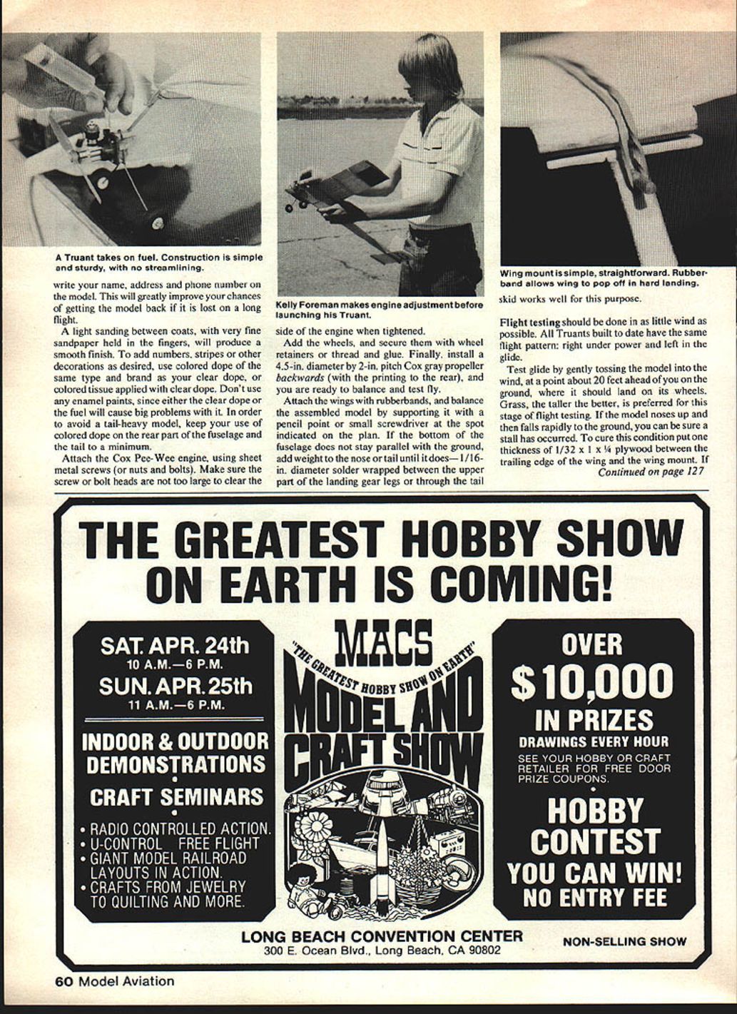
Attach the Cox Pee-Wee engine, using sheet metal screws (or nuts and bolts). Make sure the screw or bolt heads are not too large to clear the side of the engine when tightened. Kelly Foreman makes engine adjustment before launching his Truant.
Add the wheels, and secure them with wheel retainers or thread and glue. Finally, install a 4.5-in. diameter by 2-in. pitch Cox gray propeller backwards (with the printing to the rear), and you are ready to balance and test fly.
Attach the wings with rubber bands, and balance the assembled model by supporting it with a pencil point or small screwdriver at the spot indicated on the plan. If the bottom of the fuselage does not stay parallel with the ground, add weight to the nose or tail until it does — 1/16-in. diameter solder wrapped between the upper part of the landing gear legs or through the tail skid works well for this purpose.
The wing mount is simple and straightforward. The rubber band allows the wing to pop off in a hard landing. The skid works well for this purpose.
Flight testing
Flight testing should be done in as little wind as possible. All Truants built to date have the same flight pattern: right under power and left in the glide.
Test the glide by gently tossing the model into the wind, at a point about 20 feet ahead of you on the ground, where it should land on its wheels. Grass, the taller the better, is preferred for this stage of flight testing. If the model noses up and then falls rapidly to the ground, you can be sure a stall has occurred. To cure this condition, put one thickness of 1/32" x 1" x 1/4" plywood between the trailing edge of the wing and the wing mount. If the model stalls again, add another thickness of 1/32" plywood.
If the model dives quickly into the ground with no stall, put 1/32" x 1" x 1/4" plywood pieces, one at a time, between the leading edge and the wing mounts until the glide levels off.
If your test glides go straight or to the right, cut the rudder tab shown on the plan and glue it so it is deflected about 1/16" to the left as viewed from above (from the rear). Add enough left tab deflection to produce a slight left turn when test gliding. The model needs this left turn in the glide to keep it from going too sharply to the right under power.
Test-run your engine to make sure it is running reliably and to get an idea of how long it runs. The engine will probably run about a minute on a full tank of fuel. If so, launch the model with a gentle shove directly at the horizon after holding it with the engine running for about 50 seconds. If the model banks too much to the right, increase the rudder tab deflection another 1/32" to 1/16" to the left. Avoid larger deflection of the tab, as looping could result. When you have settled on the proper tab setting for your model, make sure the tab is well glued in place so you can enjoy many consistent flights.
Parts and Materials
- Balsa:
- One 3/16" x 3" x 20" (lightweight) for fuselage
- One 1/8" x 1-1/2" x 24" (lightweight) for wing
- One 1/16" x 3" x 36" (medium weight) for wing, stabilizer and rudder
- One 1/16" x 3" x 12" (medium weight) for ribs, etc.
- Plywood:
- One 1/32" x 3" x 12" for fuselage doublers
- One 1/8" x 1-5/16" x 1" for engine mount
- Wire:
- 1/16" x 7" or 8" music wire for landing gear
- Paper clip for tail skid
- Silk or gauze:
- About 10 in. x 1 in. for reinforcement
- Carpet thread:
- For landing gear reinforcement
- Dowel:
- 1/16", about 2 in. length for wing attachment
- Glue:
- Ambroid or Titebond; 5-minute epoxy
- Dope & thinner:
- Fuel-proof clear dope (3/4-oz. bottle)
- Thinner (small amount — only for brush cleaning)
- Hardware:
- Four 2-56 x 1/8" machine screws and four 2-56 blind mounting nuts or hex nuts; or four #2 sheet metal screws, 1/2" long
- Two wheel retaining springs or collars
- Two 1-3/16" or 1/4" wheels (Peck, Williams Brothers, or similar)
- Engine:
- Cox Pee-Wee .020
- Propeller:
- Cox Gray 4.5-in. dia. x 2-in. pitch
- Fuel:
- Cox
- Engine starting equipment:
- 1.5 V battery
- Cox Glow Plug Clip with wires
- Fuel dispenser (eye-dropper, etc.)
- Rubber bands:
- Three 1/16" x 2-1/4"
Transcribed from original scans by AI. Minor OCR errors may remain.

