
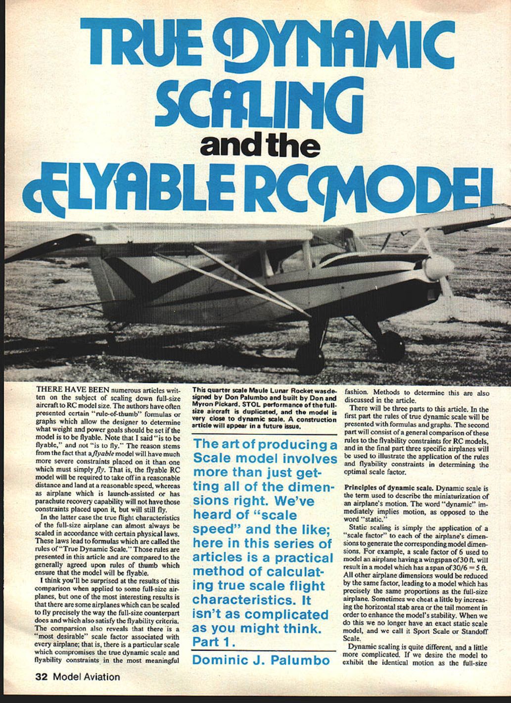
True Dynamic Scaling and the Flyable RC Model
There have been numerous articles written on the subject of scaling down full‑size aircraft to R/C model size. Authors often present "rule‑of‑thumb" formulas or graphs that let a designer determine what weight and power goals should be set if the model is to be flyable. Note that this is "flyable" and not merely "able to fly." A flyable model must take off in a reasonable distance and land at a reasonable speed; an airplane that is launch‑assisted or recovered by parachute need not satisfy those constraints, even though it will still fly.
In the latter case (where takeoff/landing constraints are relaxed) the true flight characteristics of the full‑size airplane can almost always be scaled according to certain physical laws. These laws constitute the rules of "true dynamic scale." Those rules are presented below and are compared to the generally agreed rules of thumb that ensure a model will be flyable.
There are some airplanes that can be scaled to fly precisely like their full‑size counterparts while still meeting flyability criteria. The comparison also reveals a "most desirable" scale factor for each airplane: a particular scale that best compromises true dynamic scale and flyability. Methods to determine this are discussed in the series.
This article is Part 1 of a three‑part series. Part 1 presents the rules of true dynamic scale with formulas and graphs. Part 2 compares these rules to R/C flyability constraints. Part 3 applies the rules to three specific airplanes to illustrate finding the optimal scale factor.
Dominic J. Palumbo
Principles of dynamic scale
Dynamic scale describes the miniaturization of an airplane's motion. "Dynamic" implies motion, as opposed to "static."
Static scaling simply applies a scale factor to each of the airplane's dimensions to produce a model with identical proportions. For example, a scale factor N = 6 applied to a full‑size 30 ft wingspan produces a model span of 30 / 6 = 5 ft. Occasionally we alter some dimensions (for example, increasing horizontal stabilizer area or tail moment) to improve stability; such models are not exact static scale and are called Sport Scale or Standoff Scale.
Dynamic scaling is different and a bit more complex. If a model is to exhibit the same motion as the full‑size airplane, those parameters that affect motion must be scaled consistently with the static scale factor. The most significant parameters are the forces acting on the airplane in flight — gravity, thrust, and aerodynamic forces — and the maneuver forces (because we want the model to perform within a scaled airspace).
A close look at the dynamic equations shows we need not match absolute magnitudes of all forces, only the ratios of aerodynamic, thrust, and maneuver forces to gravity (weight). Aircraft with identical ratios of thrust to weight (T/W), aerodynamic force to weight (A/W), and maneuver force to weight (M/W) will exhibit identical motion. These dimensionless ratios form the basis of dynamic scaling. The following sections show how those ratios relate to the static scale factor N.
The laws of dynamic scale
Maneuver forces, aerodynamic forces, and thrust must all be considered. We examine each in turn and derive how speed, weight, and wing area must scale.
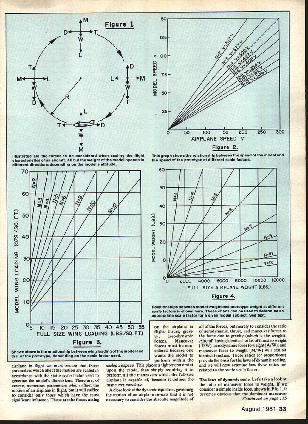
Maneuver forces (centrifugal)
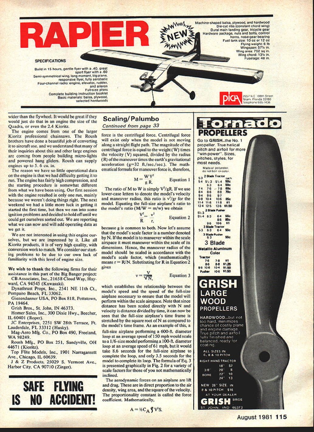
- For a simple inside loop (dominant maneuver force is centrifugal force), the centrifugal force magnitude is:
M = W V^2 / (g R) (Equation 1) where M is the maneuver force, W is weight, V is full‑size speed, R is the maneuver radius, and g is gravitational acceleration (g ≈ 32 ft/s^2).
- The ratio M/W is V^2 / (g R). For the model, using lower‑case letters, the ratio is v^2 / (g r). Equating full‑size and model ratios:
V^2 / R = v^2 / r (Equation 2)
- If the model scale factor is N, the model maneuver radius should be r = R / N. Substituting into Equation 2 gives:
v = V / sqrt(N) (Equation 3)
- Thus, model speed v must equal prototype speed V divided by sqrt(N) to keep maneuvers within scaled airspace. Note that time scales as sqrt(N): if distances scale by N and velocities by sqrt(N), the prototype's time to perform a maneuver is sqrt(N) times the model's time.
Aerodynamic forces (lift and drag)
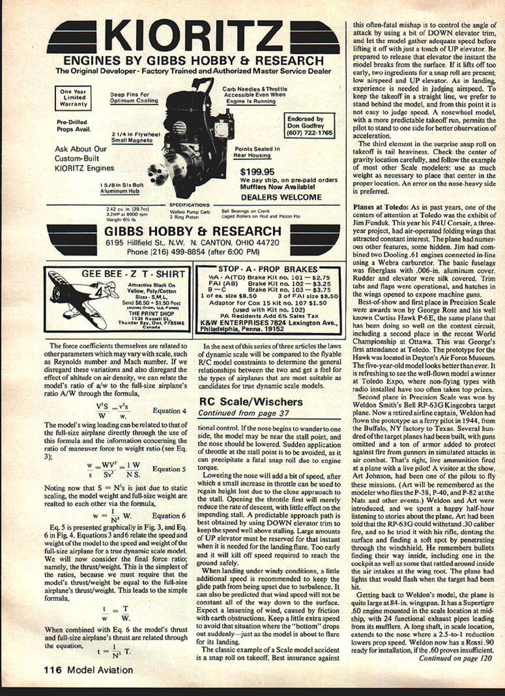
- Aerodynamic forces vary as 1/2 ρ C_A S V^2, where ρ is air density, S is wing area, V is speed, and C_A is the appropriate force coefficient (lift or drag). If the same air and airfoil section are used, C_A and ρ are effectively the same for model and prototype, so:
A/W (prototype) = (1/2 ρ C_A S V^2) / W a/w (model) = (1/2 ρ C_A s v^2) / w
- With s = S / N^2 and w = W / N^3, equating the two ratios yields:
V^2 = v^2 N (or equivalently v = V / sqrt(N)) (Equation 4)
- Thus the aerodynamic similarity requirement gives the same speed scaling as the maneuver analysis.
Thrust-to-weight ratio
- Thrust, like lift and drag, depends on area and the square of speed (assuming the same propeller/engine efficiency). If thrust scales approximately with S V^2, substituting the scale relations shows the required T/W is the same for model and prototype when speeds scale according to Equation 3.
- Because both thrust and weight scale as 1/N^3 (see below), the dimensionless thrust/weight ratio is preserved.
Dimensionless ratios summary
- True dynamic similarity requires matching three dimensionless ratios:
- T/W (thrust to weight)
- A/W (aerodynamic force to weight)
- M/W (maneuver force to weight)
- These ratios can be expressed in terms of N and prototype parameters to give practical design rules.
Scaling of wing loading, weight, and thrust
- Wing area scales as N^2; weight scales as N^3. Therefore wing loading (weight per unit area) scales as 1/N:
w = W/S = (1/N) (W_s / S_s) (Equation 5) Example: a 1/4‑scale model (N = 4) of an airplane with 40 lb/ft^2 wing loading will have 40 / 4 = 10 lb/ft^2.
- Model weight relates to prototype weight as:
W = (1/N^3) W_s (Equation 6)
- Model thrust relates to prototype thrust similarly:
T = (1/N^3) T_s
- Because both thrust and weight scale by 1/N^3, T/W remains constant between prototype and model when geometric scaling is exact.
Practical notes and limitations
- The above simple scaling rules assume aerodynamic coefficients remain the same for model and prototype. In practice, Reynolds number effects and propulsion differences (propeller efficiency, available engine RPM, etc.) may require adjustments in airfoil selection, wing area, or power to achieve similar handling qualities.
- Altitude (air density) and compressibility effects (Mach number) can also affect similarity and may require further corrections.
Figures and charts
- Figure 2 (not included here) graphically presents Equation 3 (v = V / sqrt(N)) for various scale factors.
- Figure 3 (not included) shows the relationship between model wing loading and full‑size wing loading for various scale factors (Equation 5).
- Figure 4 (not included) shows model weight versus full‑size weight for various scale factors (Equation 6).
Conclusion and next steps
- Equations 3 and 6 relate model speed and weight to prototype speed and weight for true dynamic scale models. The next article in the series will compare the laws of dynamic scale to flyable R/C model constraints to determine general relationships and identify the types of airplanes most suitable for true dynamic scale modeling.
Transcribed from original scans by AI. Minor OCR errors may remain.

