
True Dynamic Scaling and the Flyable R/C Model
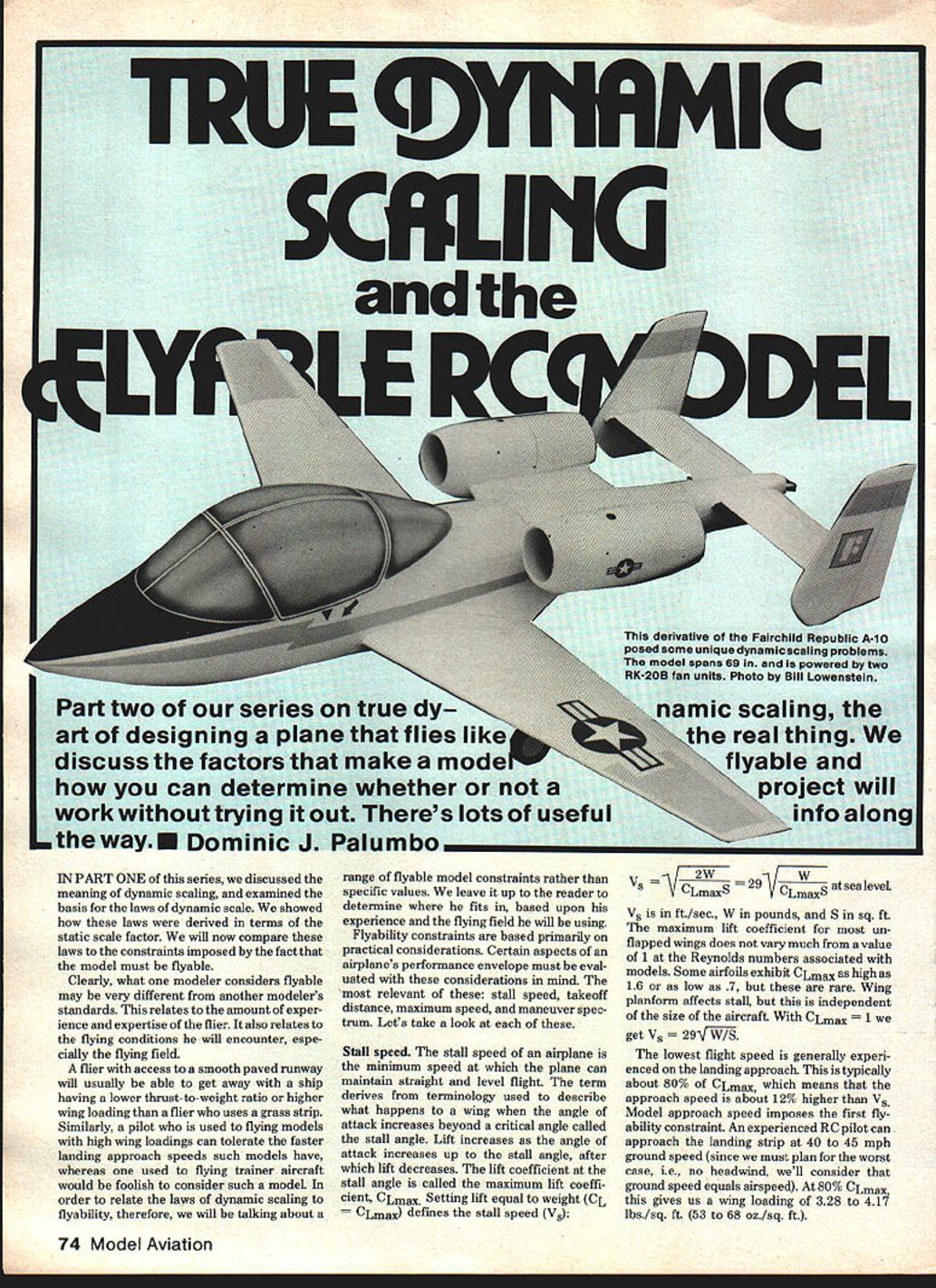
Part two of our series on true dynamic scaling, the art of designing a plane that flies like the real thing. We discuss the factors that make a model flyable and how you can determine whether or not a project will work without trying it out. There's lots of useful info along the way. Dominic J. Palumbo
Introduction
In Part One of this series, we discussed the meaning of dynamic scaling and examined the basis for the laws of dynamic scale. We showed how these laws were derived in terms of the static scale factor. We will now compare these laws to the constraints imposed by the fact that the model must be flyable.
Clearly, what one modeler considers flyable may be very different from another modeler's standards. This relates to the amount of experience and expertise of the flier and to the flying conditions he will encounter, especially the flying field.
A flier with access to a smooth paved runway will usually be able to get away with a ship having a lower thrust-to-weight ratio or higher wing loading than a flier who uses a grass strip. Similarly, a pilot who is used to flying models with high wing loadings can tolerate the faster landing approach speeds such models have, whereas one used to flying trainer aircraft would be foolish to consider such a model. In order to relate the laws of dynamic scaling to flyability, therefore, we will be talking about a range of flyable model constraints rather than specific values. We leave it up to the reader to determine where he fits in, based upon his experience and the flying field he will be using.
Flyability constraints are based primarily on practical considerations. Certain aspects of an airplane's performance envelope must be evaluated with these considerations in mind. The most relevant of these are:
- Stall speed
- Takeoff distance
- Maximum speed
- Maneuver spectrum
Stall speed
The stall speed of an airplane is the minimum speed at which the plane can maintain straight and level flight. The term derives from what happens to a wing when the angle of attack increases beyond a critical angle called the stall angle. Lift increases as the angle of attack increases up to the stall angle, after which lift decreases. The lift coefficient at the stall angle is called the maximum lift coefficient, CLmax.
Setting lift equal to weight (CL × q S = W) defines the stall speed (Vs): Vs = sqrt(2 W / (CLmax S)) = 29 sqrt(W / (CLmax S)) at sea level.
Vs is in ft/s, W in pounds, and S in sq. ft. The maximum lift coefficient for most unflapped wings does not vary much from a value of 1 at the Reynolds numbers associated with models. Some airfoils exhibit CLmax as high as 1.6 or as low as 0.7, but these are rare. Wing planform affects stall, but this is independent of the size of the aircraft. With CLmax = 1 we get Vs = 29 sqrt(W/S).
The lowest flight speed is generally experienced on the landing approach. This is typically about 80% of CLmax, which means that the approach speed is about 12% higher than Vs. Model approach speed imposes the first flyability constraint.
- An experienced R/C pilot can approach the landing strip at 40–45 mph ground speed (we must plan for the worst case, i.e., no headwind, so ground speed equals airspeed). At 80% CLmax, this gives a wing loading of about 3.28 to 4.17 lbs/sq. ft. (53 to 68 oz./sq. ft.).
- Most pilots comfortable with approach speeds around 25–30 mph require wing loadings of about 1.28 to 1.85 lbs/sq. ft. (20 to 30 oz./sq. ft.).
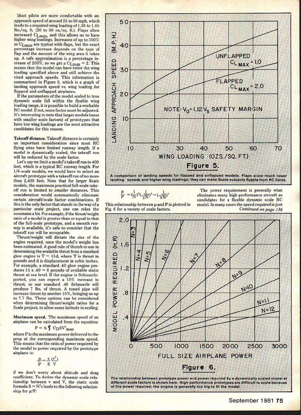
Flaps allow an increase in CLmax and therefore permit higher wing loadings. Increases up to 300% are possible depending on flap type and area; a safe approximation for design purposes is a 200% increase in CLmax (i.e., roughly double). A model with such flaps can have up to twice the wing loading specified above and still achieve the cited approach speeds. This information is summarized in Figure 5 (landing approach speed vs. wing loading for flapped and unflapped airplanes). Parameters for a model scaled by true dynamic scaling must fall within the flyable wing-loading range to make it possible to build a workable R/C model. Some factors must be adjusted. It's interesting to note that larger models (ones with smaller scale factors) of prototypes that have low wing loadings are attractive candidates for this reason.
Takeoff distance
Takeoff distance is an important consideration since R/C flying sites have limited runway length. A dynamically scaled model will have a reduced takeoff run equal to the scale factor. For example, if we limit a model's takeoff run to 400 feet (a typical R/C runway length), a 1/6-scale model would require selecting an aircraft whose prototype takeoff run is no more than 2,400 feet. Larger-scale models (smaller scale factor N) place stricter limits on the prototype's allowable takeoff run; this consideration can automatically eliminate certain aircraft/scale-factor combinations.
This constraint may stand in the way of a particular scale project, but one can relax it somewhat by selecting a higher thrust-to-weight ratio.
Thrust/weight will dictate the size of the engine required, once the model's weight has been estimated. A good rule of thumb to use in determining the available static thrust from a standard glow engine is: T = 15 d where T is thrust in pounds and d is displacement in cubic inches. For example, a standard .40 glow engine produces 15 × 0.40 = 6 pounds of available static thrust at sea level. If the engine is Schnuerle-ported, you can expect a 15% increase in thrust; so a standard .40 Schnuerle will produce about 7 lbs of thrust. A tuned pipe will increase thrust by another 10%, bringing us to roughly 7.7 lbs. These options can be considered when determining thrust/weight ratios for a scale project, to allow some latitude in scaling.
Maximum speed
The maximum speed of an airplane can be estimated from: P = (1/2) ρ S C_D V_max^3 where P is the maximum power delivered to the prop at the corresponding maximum speed. If we ignore altitude and assume similar drag coefficients, the ratio of power required by the model (p) to power required by the prototype (P) is: p / P = (s v^3) / (S V^3)
Using the static scale relationship S = N^2 leads to: p / P = (1 / N^2) (v^3 / V^3)
The relationship between p and P is plotted in Fig. 6 for a variety of scale factors.
The power requirement is generally what eliminates many high-performance aircraft as candidates for a flyable dynamic-scale R/C model. It becomes too large unless the model is quite small; then the designer is faced with the problem of finding an engine that will deliver the required power and still fit in a small model. If we consider that about 120 mph of flat-out speed is about all we can expect an R/C pilot to be able to handle, we can begin to eliminate certain possible scale subjects in the same way as when we were considering takeoff length. This can save you a lot of trouble from building an unflyable airplane.
You can calculate the power requirement for various scale factors or refer to Fig. 6 to determine if you can get the power you need from the engines available. For example, a full-scale airplane that has a 150-hp engine would require a 1.17-hp engine in a Quarter Scale model to achieve scale speed. This is quite possible with the engines available for Quarter Scale ships. If, however, your prototype is powered by a 300-hp engine, your Quarter Scale model now requires about 2.34 hp—pushing the state of the art a bit.
A word of caution: manufacturers' listings of horsepower for their engines don't always account for the de-rating effect of propellers. A good safe value to use is 70% of the manufacturer's listed horsepower rating.
You can estimate the horsepower available from a standard glow engine with: p = 1.6 d with p in horsepower and d in cubic inches of displacement. For Schnuerle-ported engines add about 10%, and if a tuned pipe is used add another 10%. Keep in mind that the thrust and power outputs of glow engines do not parallel those of typical full-scale reciprocating aircraft engines. Glow engines develop power at high rpm, whereas larger gas engines generate horsepower through lower rpm and higher torque. Thrust is proportional to torque; this is the reason for the use of speed reducers (or larger gas engines) in some Giant Scale models—even though the normal power output of some of the large glow engines would be sufficient. The important thing to remember is that thrust relates to maneuverability, whereas power relates to maximum flying speed.
Maneuverability
This consideration does not directly relate to absolute flyability, but to how well the model will duplicate the prototype’s maneuver spectrum. Two important characteristics determine this:
- Thrust-to-weight ratio
- Power-to-weight ratio
Most models can be built much lighter than the weight required for true dynamic scale and still be made to fly like the prototype; Precision Scale and Sport Scale enthusiasts have been doing this for years. A model lighter than the dynamic-scale weight will land slower and require less thrust for an equivalent thrust/weight. To duplicate authentic (heavier) landing speeds, the pilot can bring the model in a bit hotter. Similarly, if the model’s thrust/weight is greater than the prototype, it will be capable of a shorter takeoff roll—again, for scale flight you simply throttle back a bit.
There are only a few maneuvers which cannot be duplicated in true dynamic-scale fashion by an airplane that is lighter and has more thrust than dynamic-scale values. These are maneuvers where the pilot has very little intermediate control, such as:
- Spins
- Vertical dives
- Snap rolls
Generally, then, build the lightest possible model. As long as the model weight is less than the dynamic-scale weight and the thrust-to-weight is at least as large as that of the prototype, the model can be made to fly in a scale manner over the major portion of its maneuver spectrum. This is true for many airplanes, but not always possible in every case.
One generally has to strike a compromise between scale factor, weight, thrust, and power for each model. The process involves:
- Selecting a value for N (your scale factor).
- Estimating the weight of the model based on its size.
- Selecting an engine which produces the thrust and power required.
This allows you to come up with a good idea of what the model will be like at a given scale factor. Figure a range of scale factors over the range of what is practical, and select the optimum.
Part III of this series will illustrate how to do this.
Transcribed from original scans by AI. Minor OCR errors may remain.

