
True Dynamic Scaling and the Flyable RC Model
Parts One and Two of this series presented the laws of dynamic scale and a discussion of flyability constraints. In this final part, we look at two aircraft and apply the laws of dynamic scale to each. We also discuss a few prototypes that are not suitable for dynamic scaling, and explain why.
In these illustrations, the quoted takeoff distance is the distance required to clear a 50-ft. obstacle. Horsepower and thrust are sea-level (static) values.
Bellanca Citabria 150S
Figure 7 shows the dynamic scale figures for a model of this aircraft at three different scale factors (N): 1/6, 1/5, and 1/4. These figures indicate that a model at any of these scales is well within the range of existing equipment and flyability. The model can probably be built lighter than the scale weight, which improves flyability.
The thrust and power requirements can be met using available model engines. A good .19 to .23 engine will put out enough power to fly the 1/16 scale model, but the thrust would just barely equal the dynamic scale value. If the model were built to a design goal of 6 lb., which seems realistic, then the thrust-to-weight ratio of the model with a .23 would be acceptable. Alternatively, you could build to the scale weight and use a .30 or .35 engine to achieve the required thrust; in that case the model would be faster than required for dynamic scale flight. There is a much better match at 1/5 scale (N=5), where a .40 or .45 engine would fall right in. At N=4, a Schnuerle .60 with a tuned pipe would be necessary.
Cessna Turbo 337 Skymaster
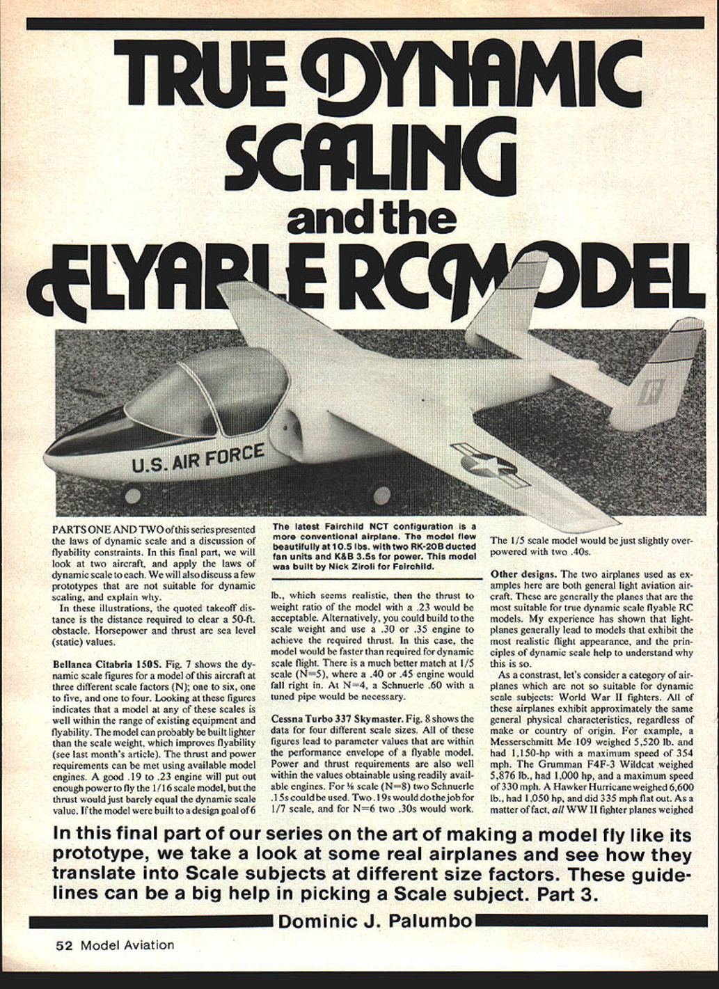
Figure 8 shows the data for four different scale sizes. All of these figures lead to parameter values that are within the performance envelope of a flyable model. Power and thrust requirements are also well within the values obtainable using readily available engines. For 1/8 scale (N=8) two Schnuerle .15s could be used. Two .19s would do the job for 1/7 scale, and for N=6 two .30s would work. The 1/5 scale model would be just slightly overpowered with two .40s.
Other designs
The two airplanes used as examples here are both general light aviation aircraft. These are generally the planes most suitable for true dynamic scale flyable RC models. Experience shows that lightplanes generally lead to models that exhibit the most realistic flight appearance, and the principles of dynamic scale help to explain why.
As a contrast, consider a category of airplanes which are not so suitable for dynamic scale subjects: World War II fighters. These airplanes exhibit approximately the same general physical characteristics regardless of make or country of origin. For example:
- Messerschmitt Me 109: weight 5,520 lb, 1,150 hp, max speed 354 mph.
- Grumman F4F-3 Wildcat: weight 5,876 lb, 1,000 hp, max speed 330 mph.
- Hawker Hurricane: weight 6,600 lb, 1,050 hp, max speed 335 mph.
In fact, most WWII fighters weighed between 4,500 and 7,000 lb, had between 1,000 and 2,000 hp, maximum speeds between 300 and 375 mph, wing areas between 175 and 260 sq ft, and wing loadings between 25 and 32 lb/sq ft.
The two characteristics that make dynamic scaling hard for these planes are:
- Maximum speed — too high for small-scale dynamic matching.
- Thrust-to-weight ratios — there isn't enough power available in small enough engines.
Nevertheless, you can build models of these airplanes that appear to fly like their full-size counterparts by working backwards: start with what powerplants are available and select a scale factor that allows a model weight giving a flyable wing loading and a reasonably similar thrust-to-weight ratio. For instance, a .60-powered model of a P-51 Mustang would have to weigh no more than 9 lb to achieve a desired thrust-to-weight ratio. A scale factor of 1/7 would give about 5.6 sq ft of wing area; at 9 lb this leads to a wing loading of about 26 oz/sq ft, similar to Pattern models. If the 1/7 scale model were built to less than 9 lb, it would be more maneuverable and slower on landing.
This technique gives you a design goal for maximum weight and allows you to select a scale factor that indicates the expected flying characteristics. When deciding whether to build a P-51 at 1/7 scale and 9 lb (or less), let your experience be your guide.
Your best approach is to estimate the overall weight based on the weight of each major component:
- Known weights: engine (including muffler, prop and spinner), fuel tank, landing gear, radio equipment.
- Estimate structural weight by relating components to structures of similar sizes you have built before.
Flying
Experienced RC pilots who have flown true dynamically scaled models for aerodynamic research will attest that it is a different kind of RC flying from what they're used to. The thrust-to-weight ratios of full-size general aviation planes are normally around 0.2 to 0.4, which is somewhat lower than typical RC airplanes. Hence, one has to get used to making moderately banked turns, gentle climb-outs, and large, graceful maneuvers. Because of this, it is not a good idea to build a model to exact dynamic scale; give yourself some margin in the flyability constraints. Knowing the values for flight parameters allows you to determine how far short of dynamic flight scale the model will be, so you can compensate with your flying style.
In conclusion, I hope this series has helped you understand more of what goes into planning a scale project. I have presented a set of laws that can be useful in that planning. I bid you readers who have had the patience to bear with me a fond adieu, and happy flying!
Dominic J. Palumbo
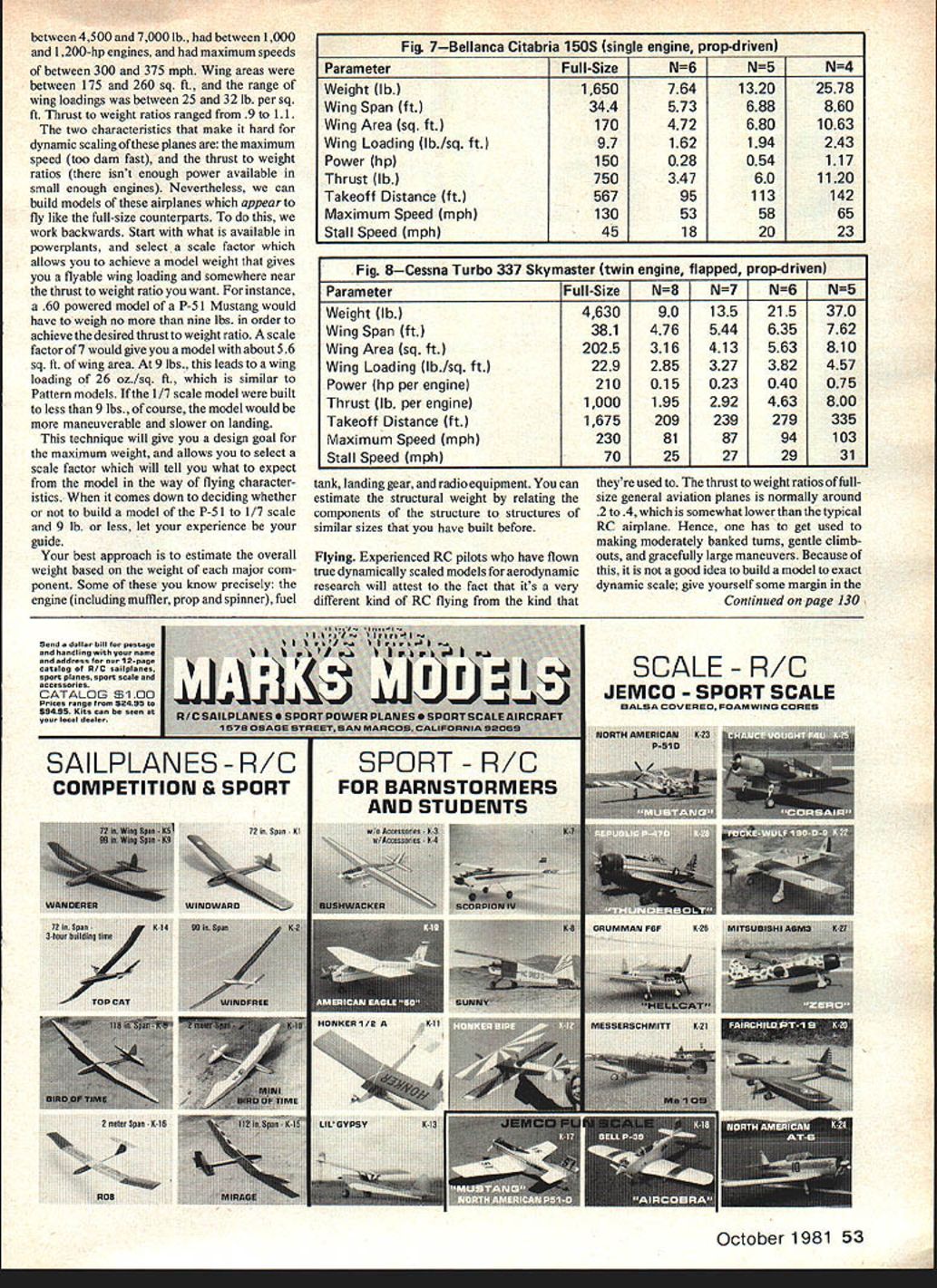
Fig. 7 — Bellanca Citabria 150S (single engine, prop-driven)
- Parameter / Full-Size / N=6 / N=5 / N=4
- Weight (lb.): 1,650 / 7.64 / 13.20 / 25.78
- Wing Span (ft.): 34.4 / 5.73 / 6.88 / 8.60
- Wing Area (sq. ft.): 170 / 4.72 / 6.80 / 10.63
- Wing Loading (lb./sq. ft.): 9.7 / 1.62 / 1.94 / 2.43
- Power (hp): 150 / 0.28 / 0.54 / 1.17
- Thrust (lb.): 750 / 3.47 / 6.00 / 11.20
- Takeoff Distance (ft.) [to clear 50 ft.]: 567 / 95 / 113 / 142
- Maximum Speed (mph): 130 / 53 / 58 / 65
- Stall Speed (mph): 45 / 18 / 20 / 23
Fig. 8 — Cessna Turbo 337 Skymaster (twin engine, flapped, prop-driven)
- Parameter / Full-Size / N=8 / N=7 / N=6 / N=5
- Weight (lb.): 4,630 / 9.0 / 13.5 / 21.5 / 37.0
- Wing Span (ft.): 38.1 / 4.76 / 5.44 / 6.35 / 7.62
- Wing Area (sq. ft.): 202.5 / 3.16 / 4.13 / 5.63 / 8.10
- Wing Loading (lb./sq. ft.): 22.9 / 2.85 / 3.27 / 3.82 / 4.57
- Power (hp per engine): 210 / 0.15 / 0.23 / 0.40 / 0.75
- Thrust (lb. per engine): 1,000 / 1.95 / 2.92 / 4.63 / 8.00
- Takeoff Distance (ft.) [to clear 50 ft.]: 1,675 / 209 / 239 / 279 / 335
- Maximum Speed (mph): 230 / 81 / 87 / 94 / 103
- Stall Speed (mph): 70 / 25 / 27 / 29 / 31
Transcribed from original scans by AI. Minor OCR errors may remain.

