
A Truly Adjustable Handle
Now it is possible to alter both the rate and force required—adjustments at the handle during flight improve maneuvers and can avoid compromise trimming of the airplane.
Robert Baron
I developed the adjustable U-control handle for control-line stunt flying about seven years ago when I realized there was a need for more precise control than was possible with commercial handles. The adjustable handle is, of course, applicable to any U-control flying when seeking improved flying qualities.
You may ask why an adjustable handle is necessary or even useful. Let's look at a typical instance of a control-line stunt plane. In the past, a standard control system was hooked to a commercial handle and we proceeded to trim out the ship. If the response was too fast, we added nose weight and conversely added tail weight if the ship was too sluggish. While this method has the virtue of simplicity, it has little else to offer as far as obtaining the most performance from a given ship.
For the moment, let us assume that the leadout attachment point is located properly. In the above instance, the plane could actually be balanced properly, but a too fast control system would make the airplane appear tail heavy. Adding nose weight to such a plane would be compromising its performance to get a proper control response or "feel." This situation is also commonly encountered in U-control combat planes. If the control system could be slowed down, the plane could be made to feel right without changing the center of gravity. Enter the adjustable control handle.
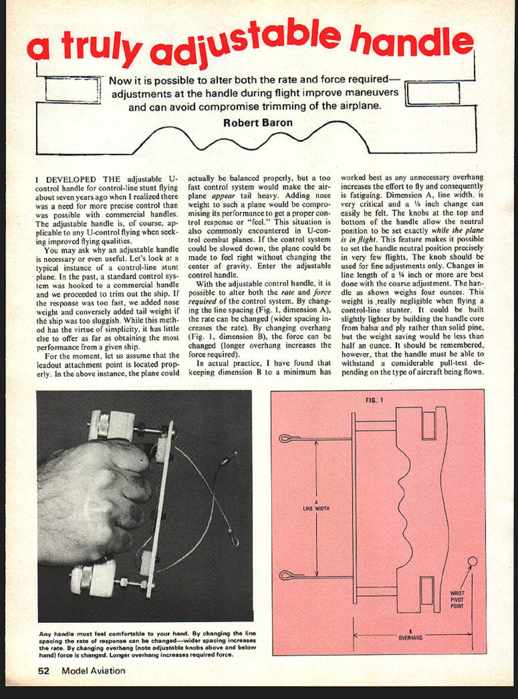
With the adjustable control handle, it is possible to alter both the rate and force required of the control system. By changing the line spacing (Fig. 1, dimension A), the rate can be changed (wider spacing increases the rate). By changing overhang (Fig. 1, dimension B), the force can be changed (longer overhang increases the force required).
In actual practice, I have found that keeping dimension B to a minimum has worked best as any unnecessary overhang increases the effort to fly and consequently is fatiguing. Dimension A, line width, is very critical and a 1/8 inch change can easily be felt. The knobs at the top and bottom of the handle allow the neutral position to be set exactly while the plane is in flight. This feature makes it possible to set the handle neutral position precisely in very few flights. The knob should be used for fine adjustments only. Changes in line length of a 1/4 inch or more are best done with the coarse adjustment. The handle as shown weighs four ounces. This weight is really negligible when flying a control-line stunter. It could be built slightly lighter by building the handle core from balsa and ply rather than solid pine, but the weight saving would be less than half an ounce. It should be remembered, however, that the handle must be able to withstand a considerable pull-test depending on the type of aircraft being flown.
Handle Construction:
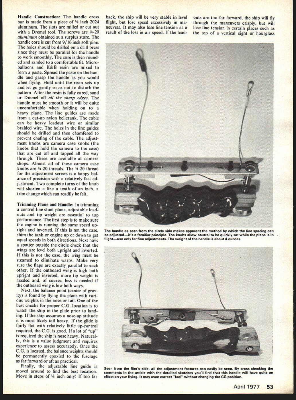
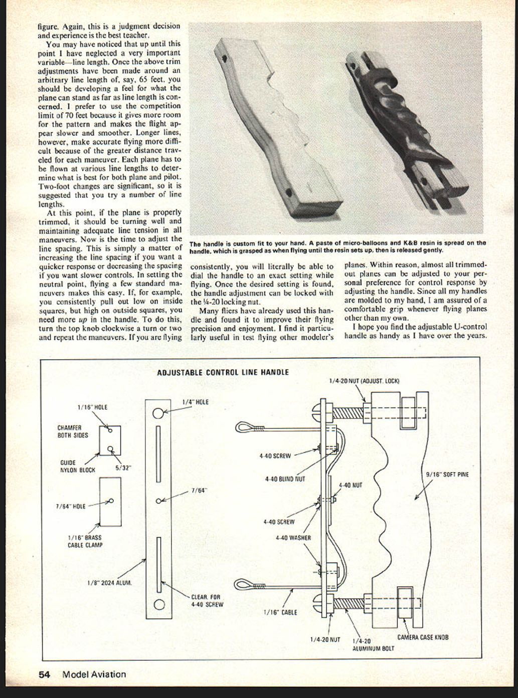
The handle cross bar is made from a piece of 1/8-inch 2024 aluminum. The slots are milled or cut out with a Dremel tool. The screws are 1/4-20 aluminum obtained at a surplus store. The handle core is cut from 9/16-inch soft pine. The holes should be drilled on a drill press since they must be parallel for the handle to work smoothly. The core is then rounded and sanded to a comfortable fit. Microballoons and K&B resin are mixed to form a paste. Spread the paste on the handle and grasp the handle as you would when flying. Hold until the resin sets up and let go gently so as not to disturb the pattern. After the resin is fully cured, sand or Dremel off all the sharp edges. The handle must be smooth or it will be quite uncomfortable when holding on to a heavy plane. The line guides are made from a cut-up nylon bellcrank. The cable can be heavy leadout wire or similar braided wire. The holes in the line guides should be drilled and then chamfered to prevent chafing of the cable. The adjustment knobs are camera case knobs (the knobs that hold the camera to the case) that are cut off and tapped all the way through. These are available at camera shops. Almost all of these camera case knobs are 1/4-20 threads. The 1/4-20 thread for the adjustment screws is a happy balance of precision with a relatively fast adjustment. Two complete turns of the knob will shorten a line a tenth of an inch, a trim change which can readily be felt.
Trimming Plane and Handle:
In trimming a control-line stunt plane, adjustable leadouts and tip weight are essential to top performance. The first step is to make sure the engine is running the same speed upright and inverted. If this is not the case, shim the tank or engine up or down to get equal speeds in both directions. Next have a spotter outside the circle check that the wings are level both upright and inverted. If this is not the case, the wing must be steamed to eliminate warps. Make very sure the flaps are exactly parallel to each other. If the outboard wing is high both upright and inverted, more tip weight is needed and, of course, less is needed if the outboard wing is low both ways.
Next, the balance point (center of gravity) is found by flying the plane with various weights in the nose or tail. One of the best checks for proper C.G. location is to watch the ship in the glide prior to landing. If the ship assumes a nose-up attitude it is most likely tail heavy. If the glide is fairly flat with relatively little up-control required, the C.G. is good. If a lot of "up" is required the ship is nose heavy. Naturally, this is a value judgment and requires experience to assess accurately. Once the C.G. is located, the balance weights should be permanently epoxied to the fuselage as far forward or aft as practical.
Finally, the adjustable line guide is moved around to find the best location. Move in steps of 1/8 inch only! If too far back, the ship will be very stable in level flight, but lose speed excessively in maneuvers. It may also lose line tension as a result of the loss in airspeed. If the leadouts are too far forward, the ship will fly through the maneuvers crisply, but will lose line tension in certain places such as the top of a vertical eight or hourglass. figure. Again, this is a judgment decision and experience is the best teacher.
You may have noticed that up until this point I have neglected a very important variable—line length. Once the above trim adjustments have been made around an arbitrary line length of, say, 65 feet, you should be developing a feel for what the plane can stand as far as line length is concerned. I prefer to use the competition limit of 70 feet because it gives more room for the pattern and makes the flight appear slower and smoother. Longer lines, however, make accurate flying more difficult because of the greater distance traveled for each maneuver. Each plane has to be flown at various line lengths to determine what is best for both plane and pilot. Two-foot changes are significant, so it is suggested that you try a number of line lengths.
At this point, if the plane is properly trimmed, it should be turning well and maintaining adequate line tension in all maneuvers. Now is the time to adjust the line spacing. This is simply a matter of increasing the line spacing if you want a quicker response or decreasing the spacing if you want slower controls. In setting the neutral point, flying a few standard maneuvers makes this easy. If, for example, you consistently pull out low on inside squares, but high on outside squares, you need more up in the handle. To do this, turn the top knob clockwise a turn or two and repeat the maneuvers. If you are flying consistently, you will literally be able to dial the handle to an exact setting while flying. Once the desired setting is found, the handle adjustment can be locked with the 1/4-20 locking nut.
Many fliers have already used this handle and found it to improve their flying precision and enjoyment. I find it particularly useful in test flying other modelers' planes. Within reason, almost all trimmed-out planes can be adjusted to your personal preference for control response by adjusting the handle. Since all my handles are molded to my hand, I am assured of a comfortable grip whenever flying planes other than my own.
I hope you find the adjustable U-control handle as handy as I have over the years.
Handle Construction
The handle cross bar is made from a piece of 1/8" 2024 aluminum. Slots are milled and cut out with a Dremel tool. Screws are 1/4-20 aluminum obtained from a surplus store. The handle core is cut from 9/16" soft pine. Holes should be drilled on a drill press since they must be parallel for the handle to work smoothly. The core is rounded and sanded for a comfortable fit.
Microballoons and K&B resin are mixed to form a paste. Spread the paste on the handle, grasp the handle as when flying and hold until the resin sets up, then let go gently so as not to disturb the pattern. After the resin has fully cured, sand and Dremel off sharp edges. The handle must be smooth; it will be quite uncomfortable to hold otherwise.
Line guides are made from cut-up nylon bellcrank cable. Heavy leadout wire or similar braided wire can be used. Holes in the line guides should be drilled and chamfered to prevent chafing.
Cable adjustment knobs are camera case knobs. The knobs that hold camera cases can be cut off and tapped 1/4-20; they are available at camera shops. 1/4-20 thread adjustment screws give a happy balance of precision and relatively fast adjustment. Two complete turns of the knob will shorten the line one-tenth inch — a trim change can be readily felt.
Trimming Plane
When trimming a control-line stunt plane with adjustable leadouts, tip weight is essential to top performance. The first step is to make sure the engine is running the same speed upright and inverted. In some cases shim the tank or engine up or down to get equal speeds in both directions. Next have a spotter outside the circle check that the wings are level both upright and inverted; in that case the wing must be steamed to eliminate warps. Make very sure flaps are exactly parallel to the other outboard wing. If the outboard wing is high both upright and inverted, tip weight is needed; of course less is needed if the outboard wing is low both ways. Next balance p
Transcribed from original scans by AI. Minor OCR errors may remain.

