

Tubestake OMT
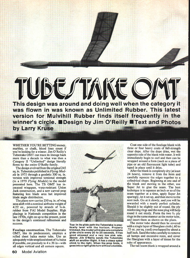
This design was around and doing well when the category it was flown in was known as Unlimited Rubber. This latest version for Mulvihill Rubber finds itself frequently in the winner's circle. Design by Jim O'Reilly. Text and photos by Larry Kruse.
Whether you're betting money, marbles, or chalk, bloodlines count if you're looking for a winner. Jim O'Reilly's Tubestake OMT traces its lineage back more than a decade to what was then a Category II "Unlimited" design literally flown by the entire O'Reilly family. The design evolved from the original 245 sq. in. Tubestake (Flying Models, 1975) through a geodetic 300 sq. in. version with improved torsional strength (Flying Models, 1979) to the model presented here.
The TS OMT has increased wingspan, warp-resistant Union Jack construction, and a new carved prop featuring less blade area but improved blade-angle distribution. The plane now carries about 250 sq. in. of wing area aloft with a nominal airframe weight of 4.22 oz., powered by strands of 1/4-in. rubber from FAI Model Supplies. High placings in Nationals competition in the late 1970s through the present point to the design's continued refinement and success.
Fuselage construction
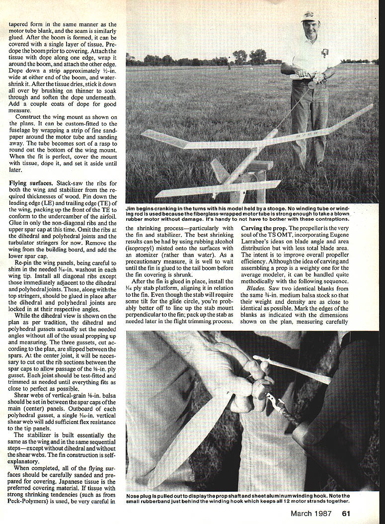
The Tubestake OMT, like its predecessors, employs a rolled-sheet balsa motor tube. Use an adequately wide unspliced sheet of 1/16-in. balsa (if possible one 6-in. wide). Cut precisely to 4 x 36 in — with all edges vertical and all corners square.
- Coat one side of the fuselage blank with three or four heavy coats of full-strength clear dope. After the dope dries, wet the opposite side of the blank with water. It will immediately begin to curl and can be wrapped around a form (such as a piece of pipe or an old fluorescent light tube) and taped in place until it dries.
- After the blank is completely dry (at least 24 hours), remove it from the form and carefully squeeze the edges together to a cylindrical shape. Beginning at one end and moving to the other, use Super Jet to glue the seam. Squeeze an inch or so of the seam together at a time, apply Super Jet sparingly, let it set up, and then move to the next inch. Work slowly for a nearly perfect cylinder. If slightly out of round, the ply reinforcing rings and the nose plug will help round it out.
- Form two 1/32-in. ply rings in the same manner as the motor tube and insert them as shown on the plans.
- Cover the motor tube with a single layer of fiberglass cloth (0.60–0.75 oz. per sq. yard), overlapped by about 1/2 in. Sand the tube carefully to remove bumps and excessive resin, then cover the fiberglass with a layer of tissue for appearance.
- The tail-boom blank is wrapped around a tapered form in the same manner as the motor-tube blank; glue the seam the same way. Pre-dope the boom prior to covering: attach tissue and dope along one edge, wrap around the boom and attach the other edge. Dope down a strip approximately 1/2 in. wide at either end of the boom to water-shrink. After the tissue dries, stick it down by brushing thinner to soak through and soften the dope underneath. Add a couple of coats of dope as a good measure.
- Construct the wing mount shown on the plans, or custom-fit it to the fuselage by wrapping a strip of fine sandpaper around the motor tube and sanding away until the tube becomes a sort of rasp and rounds out the bottom. When the wing mount fits perfectly, cover it with tissue and dope and set aside until later.
Complete the nose assembly by laminating the nose block from cross-grain sheet balsa. Trim the spruce or basswood plug so it fits snugly into the ply reinforcing ring. Note the nose plug has a section removed and glued to the fuselage proper as an indexing key. Install the 1/4-in. O.D. hard-aluminum rear motor anchor tube, the dethermalizer (DT) stuffer tube, the lower DT anchor dowel, and the 1/8-in. sheet-aluminum winding hook as the last items.
Flying surfaces
- Stack-saw ribs for both wing and stabilizer to the required thicknesses of wood. Pin down the leading edge (LE) and trailing edge (TE), packing up the front TE to conform to the undercamber airfoil. Glue non-diagonal ribs and the upper spar cap at this time. Omit ribs at the dihedral/polyhedral joints; install turbulator stringers now.
- Remove the wing from the building board and add the lower spar cap. Re-pin the wing panels, shimming where needed to obtain 1/16-in. washout at the wing tip. Install diagonal ribs except immediately adjacent to the dihedral/polyhedral joints. Glue the top stringers in place after the dihedral/polyhedral joints are locked at their respective angles (see dihedral view on the plan).
- The dihedral/polyhedral gussets actually set the needed angles. Usually, after propping up and measuring, three gussets cut according to the plan are slipped between the spars at the center joint. Cut out rib sections between spar caps to allow passage of the 1/8-in. ply gusset joint. Test-fit and trim each joint until everything fits as close to perfect as possible.
- Set shear webs of vertical-grain 1/16-in. balsa between the spar caps in the main center panels. An outboard polyhedral gusset plus a single 1/16-in. vertical shear web will add sufficient flex resistance.
- The stabilizer is built essentially the same as the wing (same sequential steps—except without dihedral and without the shear webs). Fin construction is straightforward.
- When completed, sand all flying surfaces and prepare for covering. Japanese tissue is the preferred covering material. If using tissue with strong shrinking tendencies, be careful in the shrinking process—particularly with the fin and stabilizer. Best results are obtained by misting rubbing alcohol (isopropyl) with an atomizer rather than using water. As a precaution, wait until the fin is glued to the tail boom before shrinking the fin covering.
- After the fin is glued in place, install the 1/8-in. ply stab platform, aligning it in relation to the fin. Although the stab will require some tilt for the glide circle, it is usually best to line up the stab mount perpendicular to the fin and pack up the stab as needed later during flight trimming.
- Add braided fishing-line turbulators to both the wing and the prop. Place the turbulator atop the front stringer of the wing and approximately 10% aft of the leading edge of the prop. Both turbulators may be doped in place.
Carving the prop
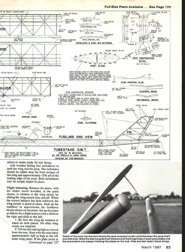
The propeller is the soul of the TS OMT, incorporating Eugene Larrabee's ideas on blade angle and area distribution but with less total blade area to improve overall efficiency. Carving and assembling the prop is handled methodically as follows.
#### Blades
- Saw two identical blanks from the same 3/4-in. medium balsa stock so their weight and density are as close to identical as possible. Mark the edges and dimensions as shown on the plan and measure carefully.
- Clamp the blanks together and carve the profiles simultaneously to keep both blades identical. After carving, sand them smooth and harden the surfaces with thin CA or a light coat of dope. Balance the blades and finish as required.
- On the back surface (selected as the front face while carving), draw a smooth curved line through the series of points shown on the plan isometric view and carve the back side down to that line. Carve in the slight undercamber shown and sand to final contour. Carve the front face to the airfoil section on the plan and final-sand each blade in preparation for doping. Use enough coats of dope to give the blades a definite sheen.
#### Hub and shaft
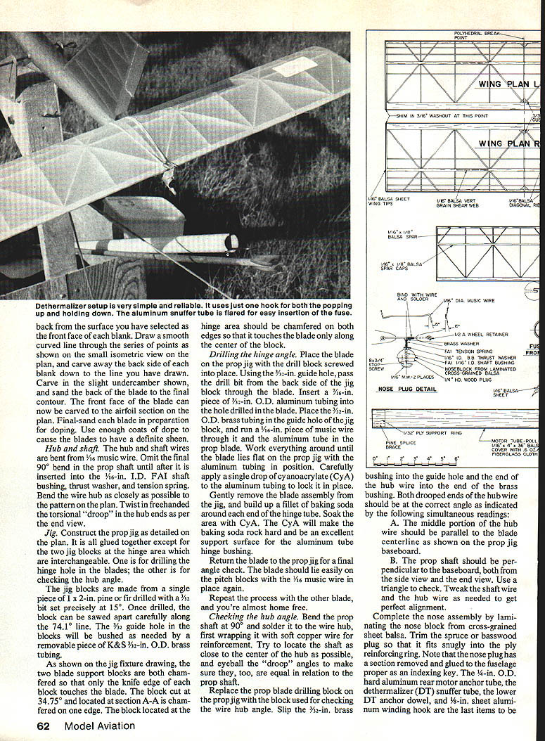
- Bend the hub and shaft from 1/16-in. music wire. Omit the final 90° bend in the prop shaft until after it is inserted into the 1/16-in. I.D. FAI shaft bushing, thrust washer, and tension spring.
- Bend the wire hub closely to the pattern on the plan. Twist in freehand the torsional “droop” in the hub ends as per the end view.
#### Jig
- Construct the prop jig as detailed on the plan. It is all glued together except for the two jig blocks at the hinge area, which are interchangeable: one for drilling the hinge hole in the blades and the other for checking the hub angle.
- Make the jig blocks from a single piece of 1 x 2 x 2-in. pine or fir drilled with a 3/32-in. bit set precisely at 15°. Once drilled, saw the block apart carefully along the 74-1/2° line. The 3/32-in. guide hole in the blocks will be bushed as needed by a removable piece of K&S 3/32-in. O.D. brass tubing.
- The two blade support blocks are chamfered so that only the knife edge of each block touches the blade. The block cut at 34.75° (section A–A) is chamfered on one edge. The block at the hinge area should be chamfered on both edges so it touches the blade only along the center.
#### Drilling the hinge angle
- Place a blade on the prop jig with the drill block screwed into place. Using the 3/32-in. guide hole, pass the drill bit from the back side of the jig block through the blade.
- Insert a 7/16-in. piece of 3/32-in. O.D. aluminum tubing into the hole drilled in the blade. Place the 3/32-in. O.D. brass tubing in the guide hole of the jig block, and run a 1/16-in. piece of music wire through it and the aluminum tube in the prop blade. Work everything around until the blade lies flat on the prop jig with the aluminum tubing in position.
- Carefully apply a single drop of cyanoacrylate (CyA) to the aluminum tubing to lock it in place. Gently remove the blade assembly from the jig and build up a fillet of baking soda around each end of the hinge tube. Soak the area with CyA. The CyA will make the baking-soda fillet rock hard and be an excellent support surface for the aluminum tube hinge bushing.
- Return the blade to the prop jig for a final angle check. The blade should lie easily on the pitch blocks with the 1/16-in. music wire in place again. Repeat for the other blade.
#### Checking the hub angle
- Bend the prop shaft at 90° and solder it to the wire hub, first wrapping the joint with soft copper wire for reinforcement. Locate the shaft as close to the center of the hub as possible and eyeball the droop angles to ensure they are equal relative to the prop shaft.
- Replace the prop-blade drilling block on the prop jig with the block used for checking the wire-hub angle. Slide the 1/2-in. brass bushing into the guide hole and insert the end of the hub wire into the brass bushing.
- Both drop-rod ends of the hub wire should be at the correct angle as indicated by these simultaneous readings:
- A. The middle portion of the hub wire should be parallel to the blade centerline as shown on the prop jig baseboard.
- B. The prop shaft should be perpendicular to the baseboard, both from the side view and the end view. Use a triangle to check. Tweak the shaft wire and hub wire as needed to get perfect alignment.
Complete the nose assembly and install the remaining hardware as described in the fuselage section.
Flight trimming
Balance the plane, with the rubber motor installed, at the point shown on the plans in relation to the wing chord by sliding the wing mount fore and aft. When the correct balance has been achieved, glue the wing mount in place. Pack up the stabilizer to approximate the incidence blocks shown on the plans. Set up the plane for a flight pattern with a climb to the right and a glide to the left:
- Ensure the wing tip washout is equal on both panels. No other wing warps are required.
- Tilt the left stab tip high as viewed from the rear. Start with the stab tilted approximately half as high as the left main wing panel. If the glide circle is too tight, reduce the tilt. If it is too open and wandering, increase the tilt by 1/2° at a time.
- Offset the rudder tab to the left as required to achieve a glide circle of about 20 to 25 seconds in calm air.
- Offset the nose block approximately 2° to 3° right thrust and 3° to 5° downthrust.
- Key the wing and stab to maintain consistent trim.
Hand-glide the ship a few times to ensure it behaves. Then begin powered flights gently and incrementally. Start with enough winds in the motor for the plane to sustain power flight on its own—but not so many winds that a mishap will cause destruction. Lots of time spent building a plane demands lots of time and practice to get it flying well.
Desired flight path: a continuous vertical spiral to the right with decreasing climb angle as motor torque lessens. By the time the prop folds, the plane should be leveled and transition smoothly from the right-hand power pattern into the left-hand glide. Any wavering or discontinuity in the spiral climb to the right may indicate a need for a CG change or a thrust change.
Common problems and solutions:
- Problem: The plane tries to start a wingover about eight to 10 seconds into a full-power flight.
- Solution 1: If the wingover is at fairly constant speed, reduce the right thrust slightly.
- Solution 2: If the plane slows before commencing the wingover, the CG may be too far aft. Move the wing forward 1/8 in., then recheck and readjust the glide.
- Problem: The plane tends to spiral in the glide when encountering strong thermal activity.
- Solution: Reduce the rudder tab setting a bit to open up the glide turn.
Weights and motor
The model flies on 2.8 oz. (4-in. FAI) rubber made up into a 12-strand motor, giving an all-up weight just over 7 oz. Suggested component weights:
- Wing ................................ 1.61 oz.
- Fuselage ............................ 1.60 oz.
- Prop assembly ....................... 0.59 oz.
- Stabilizer ........................... 0.34 oz.
- Winding hook ........................ 0.08 oz.
- Airframe weight ..................... 4.22 oz.
- Rubber ................................ 2.80 oz.
- Total weight ........................ 7.02 oz.
The model could be built lighter, but for a midday or thirsty rider there's little incentive to do so; it is already difficult to dethermalize from strong lift. At the 1985 Ft. Worth Planesmen Labor Day Contest, the TS OMT had a worrisome flight in which it drifted around for about 4 minutes with the tail popped up—and no apparent loss of altitude.
If you choose to build the TS OMT, Jim O'Reilly would be happy to correspond about the design. Address: Jim O'Reilly, 4760 N. Battin, Wichita, KS 67220. Given its long lineage of success in the hands of the O'Reilly clan, it is certainly worthy to consider as your Mulvihill entry for the next contest season.
Transcribed from original scans by AI. Minor OCR errors may remain.

