
Tucano T-27
Joseph R. Naber
Introduction
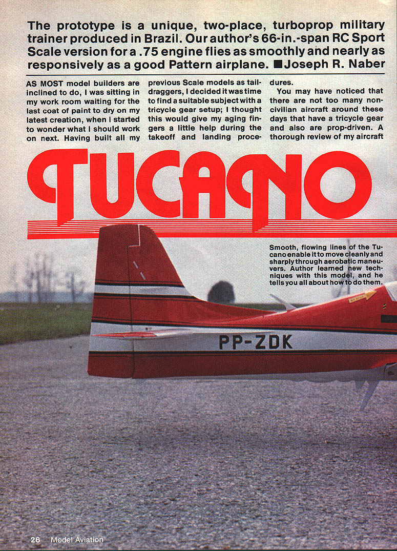
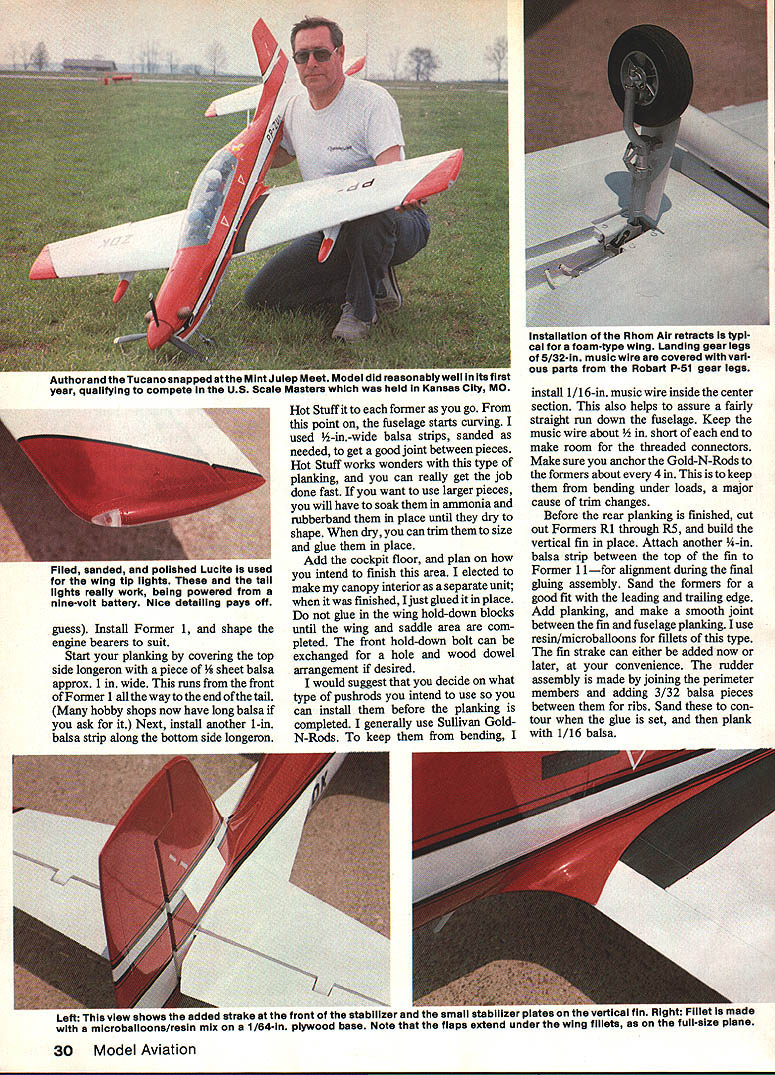
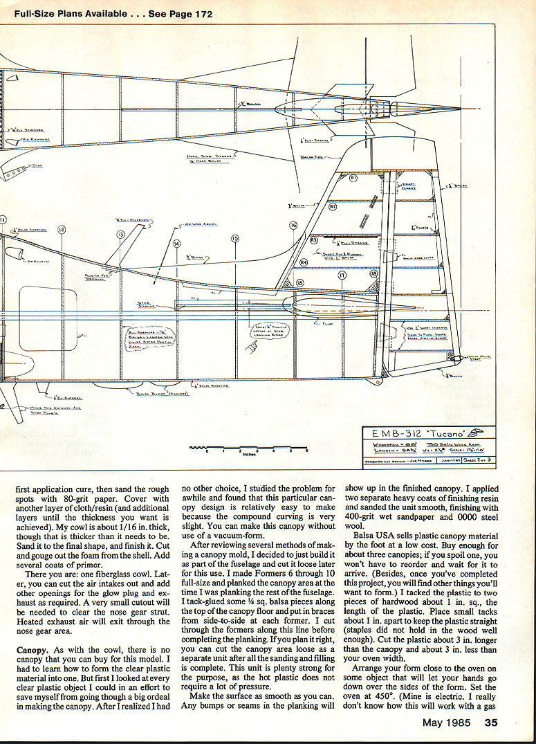
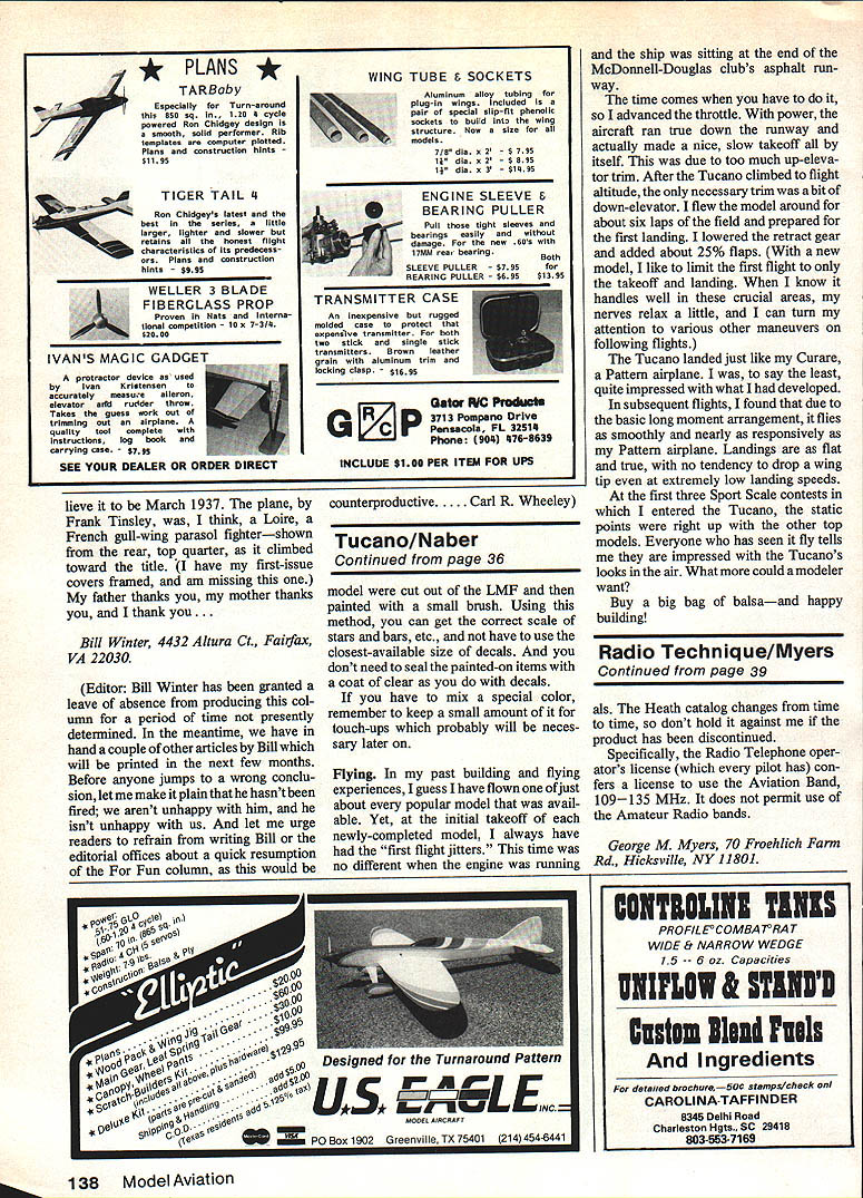
The prototype is a unique, two-place, turboprop military trainer produced in Brazil. My 66-in.-span RC Sport Scale version for a .75 engine flies as smoothly and nearly as responsively as a good Pattern airplane.
As most model builders are inclined to do, I was sitting in my work room waiting for the last coat of paint to dry on my latest creation when I started to wonder what I should work on next. Having built all previous Scale models as taildraggers, I decided it was time to find a suitable subject with a tricycle gear setup; I thought this would give my aging fingers a little help during the takeoff and landing procedures.
You may have noticed that there are not too many non-civilian aircraft around these days that have a tricycle gear and are also prop-driven. A thorough review of my aircraft books did nothing to help the matter—until I picked up the then-current issue of Air International magazine, which had an ad for the Brazilian EMB-312 Tucano. This was a twin-seat, turboprop trainer. The minute I saw the photo, I knew it had the features of the aircraft I wanted to build in model form. I wrote to the sales office listed in England, and several weeks later they were kind enough to send me a very detailed brochure with pictures and three-view drawings. After reviewing the literature, I knew instantly that I had made the right choice.
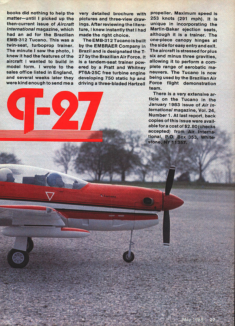
The EMB-312 Tucano is built by the EMBRAER Company in Brazil and is designated the T-27 by the Brazilian Air Force. It is a tandem-seat trainer powered by a Pratt & Whitney PT6A-25C free turbine engine developing 750 static hp and driving a three-bladed Hartzell propeller. Maximum speed is 253 knots (291 mph). It is unique in incorporating Martin-Baker ejection seats, although it is a trainer. The one-piece canopy hinges at the side for easy entry and exit. The aircraft is stressed for plus six and minus three gravities, allowing it to perform a complete range of aerobatic maneuvers. The Tucano is now being used by the Brazilian Air Force flight demonstration team.
There is a very extensive article on the Tucano in the January 1983 issue of Air International magazine, Vol. 24, Number 1. At last report, back copies of this issue were available for a cost of $2.80 (checks accepted) from Air International, P.O. Box 353, Whitestone, NY 11357.
Brazil is trying to sell this aircraft to other countries—and has sold some to Egypt. In the near future, we should be seeing some varied paint schemes for our modeling use.
It was from the above information that I developed my model plans by using a projector to enlarge the three-views to the size needed. I was influenced by several kit models I had recently built having larger-than-.60 engines and wingspans of 60 in. or more; I found that these models flew much nicer than the models with heavier wing loadings that I used to build. After examining several wingspan/powerplant combinations, I initially settled on a .90 engine and 68-in. wingspan. As the model developed, I began to feel the .90 engine would be too powerful. I changed to a .75 cu. in. Supertigre, which has proved to be very effective and has served me quite well. I also know now that a good .60 engine has plenty of power to fly this aircraft—due to the model's lightness (for its size) and its aerodynamically clean configuration.
I proceeded to draw up the plans, adding formers and other details as required. After several preliminary sketches and shuffling of pieces, I arrived at the final setup I thought I wanted. It is amazing how much time one can spend deciding which assembly methods will give the best results and most efficient use of materials. Even simple things take time—like whether the wing should be bolted in front or use a dowel-and-hole arrangement. Consideration of radio gear, wing construction, and various other items all come into play during this choice process. Ultimately, this is what is enjoyable, as you get to use construction methods you are comfortable with and use materials which suit your building techniques best.
The only deviation from scale that I had to make for the model is in the location of the nose gear strut. Because of the inverted engine, I had to move it rearward. This, however, is not nearly as noticeable as a side-mounted-engine alternative would be (with the cylinder sticking out in the breeze).
I elected to have retracting landing gear and flaps, and I also decided to install bomb-dropping mechanisms in the wing pylons; however, these are not shown on the plans.
Construction
The text below assumes you have a varied knowledge of building techniques and some familiarity with the materials and ideas used in this model. If you are not past the square-fuselage type of model, you may have trouble with some aspects unless you have experienced friends to help. But then, who hasn't tried to build a model before they knew everything about what they were doing? As a matter of fact, I did that very thing with this project; this is how we learn.
After reading this article through, you will see that you will have to learn to form a clear-plastic canopy mold and make a fiberglass cowl. Making these items for the prototype model was the first time for me, and both of them worked out quite well. After reading how I made my canopy mold (if you decide to do yours the same way), you must adjust the cutting of the fuselage formers to include the uppermost part of the formers. The correct outline of the canopy is shown, but you must make allowance for the thickness of the balsa sheeting.
Fuselage
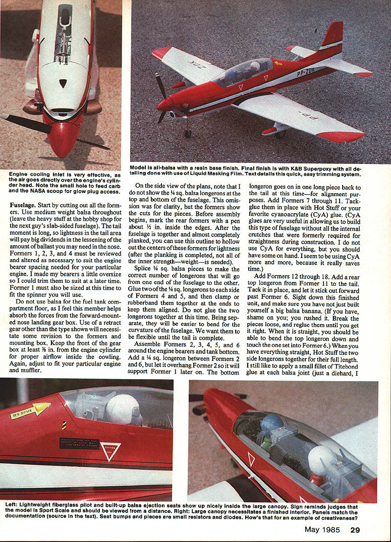
Start by cutting out all the formers. Use medium-weight balsa throughout (leave the heavy stuff at the points where the next guy's slab-sided fuselage will be). The tail moment is long, so lightness in the tail area will pay big dividends in the lessening of the amount of ballast you may need in the nose. Formers 1, 2, 3 and 4 must be reviewed and altered as necessary to suit the engine bearer spacing needed for your particular engine. I made my bearers a little oversize so I could trim them to suit at a later time. Former 1 must also be sized at this time to fit the spinner you will use.
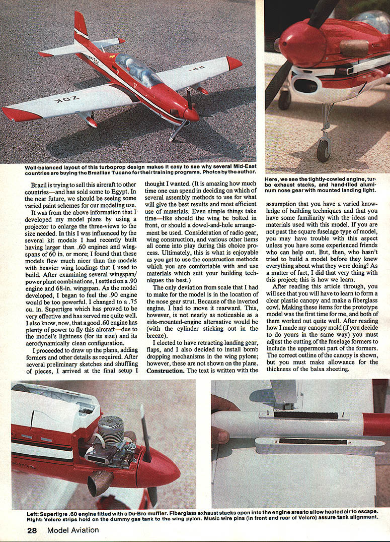
Do not use balsa for the fuel tank compartment floor, as this member helps absorb the forces from the forward-mounted nose landing gear box. Use of a retractable gear other than the type shown will necessitate some revision to the formers and mounting box. Keep the front of the gear box at least 3/8 in. from the engine cylinder for proper airflow inside the cowling. Adjust to fit your particular engine and muffler.
On the side view of the plans, note that I do not show the 1/4 sq. balsa longerons at the top and bottom of the fuselage. This omission was for clarity, but the formers show the cuts for the pieces. Before assembly begins, mark the rear formers with a pen about 1/2 in. inside the edges. After the fuselage is together and almost completely planked over, you can use this outline to hollow out the centers of those formers for lightness (after the planking is completed, not all of the inner strength is needed).
Splice 1/4 sq. balsa pieces to make the correct number of longerons that will go from one end of the fuselage to the other. Glue two of the 1/4 sq. longerons to each side of Formers 4 and 5, and then clamp or rubberband them together at the ends to keep them aligned. Do not glue the two longerons together at this time. Being separate, they will be easier to bend for the curvature of the fuselage. We want them to be flexible until the tail is complete.
Assemble Formers 2, 3, 4, 5, and 6 around the engine bearers and tank bottom. Add a 1/4 sq. longeron between Formers 2 and 6, but let it overhang Former 2 so it will support Former 1 later on. The bottom longeron goes in on one long piece back to the tail at this time—for alignment purposes. Add Formers 7 through 11. Tack them in place with Hot Stuff or your favorite cyanoacrylate (CyA) glue. CyA glues are very useful in allowing us to build this type of fuselage without all the internal crutches that were formerly required for straightness during construction. I do not use CyA for everything, but you should have some on hand. I seem to be using CyA more and more because it really saves time.
Add Formers 12 through 18. Add a rear top longeron from Former 11 to the tail. Tack it in place, and let it stick out forward past Former 6. Sight down this finished unit, and make sure you have not just built yourself a big balsa banana. If you have, break the pieces loose, and reglue them until you get it right. When it is straight, you should be able to bend the top longeron down and touch the one set into Former 6. When you have everything straight, Hot Stuff the two side longerons together for their full length. I still like to apply a small fillet of Titebond glue at each balsa joint.
Install Former 1, and shape the engine bearers to suit.
Start your planking by covering the top side longeron with a piece of 1/8-in. sheet balsa approximately 1 in. wide. This runs from the front of Former 1 all the way to the end of the tail. Next, install another 1-in. balsa strip along the bottom side longeron. Hot Stuff it to each former as you go. From this point on, the fuselage starts curving. I used 1/2-in.-wide balsa strips, sanded as needed, to get a good joint between pieces. Hot Stuff works wonders with this type of planking, and you can really get the job done fast. If you want to use larger pieces, you will have to soak them in ammonia and rubberband them in place until they dry to shape. When dry, you can trim them to size and glue them in place.
Add the cockpit floor, and plan how you intend to finish this area. I elected to make my canopy interior as a separate unit; when it was finished, I just glued it in place. Do not glue in the wing hold-down blocks until the wing and saddle area are completed. The front hold-down bolt can be exchanged for a hole and wood dowel arrangement if desired.
Decide on the type of pushrods you intend to use so you can install them before the planking is completed. I generally use Sullivan Gold N-Rods. To keep them from bending, I install 1/16-in. music wire inside the center section. This also helps to assure a fairly straight run down the fuselage. Keep the music wire about 1/2 in. short of each end to make room for the threaded connectors. Make sure you anchor the Gold-N-Rods to the formers about every 4 in. This is to keep them from bending under loads, a major cause of trim changes.
Before the rear planking is finished, cut out Formers R1 through R5, and build the vertical fin in place. Attach another 1/4-in. balsa strip between the top of the fin and Former 11—for alignment during final gluing assembly. Sand the formers for a good fit with the leading and trailing edge. Add planking, and make a smooth joint between the fin and fuselage planking. I use resin/microballoons for fillets of this type. The fin strake can either be added now or later, at your convenience. The rudder assembly is made by joining the perimeter members and adding 3/32-in. balsa pieces between them for ribs. Sand these to contour when the glue is set, and then plank with 1/16-in. balsa.
This is a good time to cut out the stab ribs and build the stab assembly over the plan. In place of the music wire elevator stiffener shown, I purchased a preformed Sig connector with a nylon horn already attached in the center. It takes a little more work to use this method, but it hides the elevator horn within the fuselage, and the effort will be appreciated later on when the model has been completed. When you have built the stab and elevator, set them aside until you have finished the wing.
Wing
Cut out the center section and tip templates from 1/8 plywood. If you do not have a wire foam cutter, ask around in your area for someone who can help. You are almost sure to find someone who can cut them for you. If so, ask if you can help—you'll want to get some experience on how it is done (you may want to make your own cutter someday). This person also will know where to get the required foam. If you cannot find anyone to help, there are companies that have advertised in this magazine offering to do custom foam cutting, if you furnish the templates and your money.
After the foam cores are in your possession, add the leading and trailing edges. Mark an accurate centerline through the tip, front to back. We will use this later for alignment.
Make the necessary cutouts for the aileron bellcrank assemblies and the retract gear assemblies. To install the aileron pushrods, make two long parallel cuts 1/4 in. apart, and remove the foam between them. Install the Gold-N-Rods, and glue them in place. Reinstall the foam, using Titebond glue. (If the foam cannot be reused because it is in little pieces, install a soft piece of 1/4-in. balsa and sand flush with the top of the foam core.)
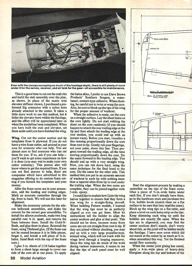
I glue 3-in. sheets of 1/16 balsa together to form a sheet large enough to cover one side of the core all in one piece. To apply the balsa skins, I prefer to use Dave Brown Products' Southern Sorgum, a water-based, contact-type adhesive. When sheeting, be careful not to twist or warp the core. Also, be sure to block up the tips of the wing for the proper amount of washout.
When the adhesive is ready, set the core on a straight surface. Lay the sheet balsa on the core lightly. Do not start rubbing the sheet on the core randomly—if you should happen to attach the rear trailing edge at the tip and then attach the leading edge at the root section, you could end up with an instant warp. Before you start, visualize a line running proportionally down the core from root to tip. Gently rub your fingertips, not your palm, down this line. Then progress toward the trailing edge, all the time moving proportionally down the core. Do the same forward to the leading edge. You should end up with a very straight wing. Now you can rub down hard, using the same technique for the final bond to the core. Do the same for the other side. This method lets you put in an accurate amount of washout in each tip with nothing more than a tapered shim from tip to root under the trailing edge. When the two cores are complete, they can be joined together with 5-min. epoxy.
I would like to explain how I join the wing halves together to ensure they form a true wing for a straight-flying aircraft. When building Pattern models, I learned that the wing tips must be as perfectly aligned as you can get them. Most kit instructions tell the builder to align the center sections and glue at that point. This should not be done, because many foam cores are not cut straight from root to tip. If they are joined without checking, you may end up with a very large propeller-type, twisted wing, which will not track with the wings level through a looping maneuver. Since the wing tips do much of the work during various maneuvers, the tips of each panel must be well aligned.
Start the alignment process by making a centerline on the tips of the foam cores. Glue a piece of 1/4-in.-wide balsa under each line. If you don't already have them, purchase two 6-in. bubble levels (match them on a flat surface to be sure that they read the same). Block up the wing tips on a flat table, and place a level on each balsa strip on the tips. Keep shimming each wing tip until the bubbles are exactly the same. When the tips are in alignment, you may find the center sections don't match; don't worry about this, as this joint will be hidden inside the fuselage. I have seen cores which did not match at the center by as much as 1/4 in. when assembled this way. Yet the finished model flew correctly.
When the center joint gluing has cured, apply a 4-in.-wide piece of heavy-duty fiberglass along the top and bottom of the centerline joint. I find it is best to use finishing resin for this application.
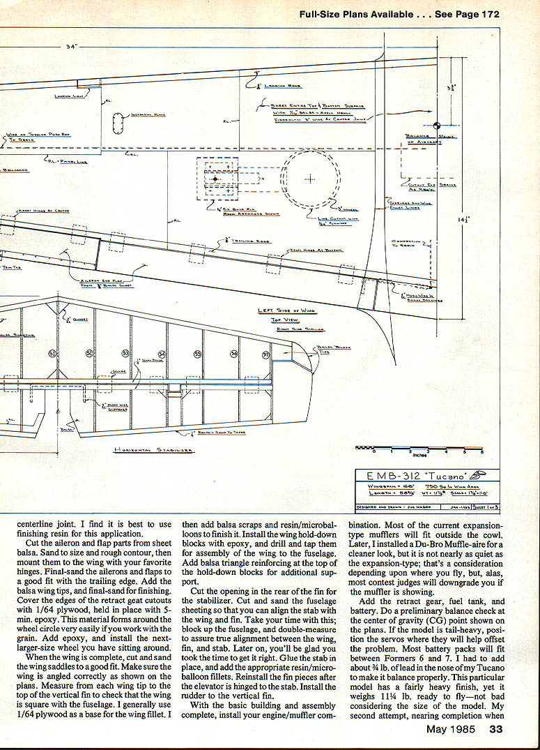
Cut the aileron and flap parts from sheet balsa. Sand to size and rough contour, then mount them to the wing with your favorite hinges. Final-sand the ailerons and flaps to a good fit with the trailing edge. Add the balsa wing tips, and final-sand for finishing. Cover the edges of the retract gear cutouts with 1/64-in. plywood, held in place with 5-min. epoxy. This material forms around the wheel circle very easily if you work with the grain. Add epoxy, and install the next-larger-size wheel if you have one sitting around. When the wing is complete, cut and sand the wing saddles to a good fit. Make sure the wing is angled correctly as shown on the plans. Measure from each wing tip to the top of the vertical fin to check that the wing is square with the fuselage. I generally use 1/64-in. plywood as a base for the wing fillet. I then add balsa scraps and resin/microballoons to finish it. Install the wing hold-down blocks with epoxy, and drill and tap them for assembly of the wing to the fuselage. Add balsa triangle reinforcing at the top of the hold-down blocks for additional support.
Cut the opening in the rear of the fin for the stabilizer. Cut and sand the fuselage sheeting so that you can align the stab with the wing and fin. Take your time with this; block up the fuselage and double-measure to assure true alignment between the wing, fin, and stab. Later on, you'll be glad you took the time to get it right. Glue the stab in place, and add the appropriate resin/microballoon fillets. Reinstall the fin pieces after the elevator is hinged to the stab. Install the rudder to the vertical fin.
With the basic building and assembly complete, install your engine/muffler combination. Most of the current expansion-type mufflers will fit outside the cowl. Later, I installed a Du-Bro Muffle-aire for a cleaner look, but it is not nearly as quiet as the expansion-type; that's a consideration depending upon where you fly, and most contest judges will downgrade you if the muffler is showing.
Add the retract gear, fuel tank, and battery. Do a preliminary balance check at the center of gravity (CG) point shown on the plans. If the model is tail-heavy, you will have to add weight to the nose to have the model fly properly. Most battery packs will fit between Formers 6 and 7. I had to add about 3/4 lb of lead in the nose of my Tucano to make it balance properly. This particular model has a fairly heavy finish, yet it weighs 11 1/2 lb. ready to fly—not bad considering the size of the model. My second attempt, nearing completion when this was written, was weighing 10 lb. with no ballast up front.
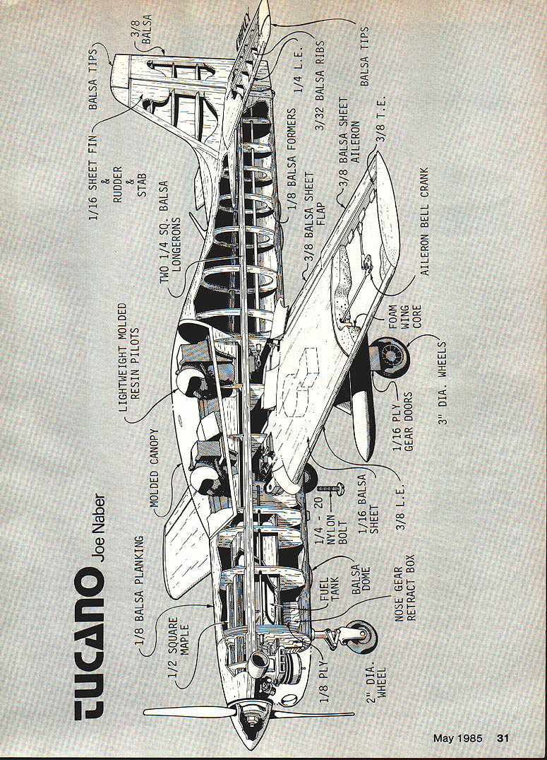
Plans details (parts and materials)
- 1/8 balsa planking
- Molded canopy
- Lightweight molded resin pilots
- 1/16 sheet fin
- Rudder & stab balsa
- Two 1/4 sq. balsa longerons
- 1/8 balsa formers
- 1/4 L.E.
- 3/32 balsa ribs
- 3/8 balsa sheet flap
- 3/8 balsa sheet aileron
- 3/8 L.E.
- Balsa tips
- 1/2 square maple
- 1/8 ply
- 2" dia. wheel
- Nose gear retract box
- Nose gear
- Fuel tank
- Balsa dome
- 1/4-20 nylon bolt
- 1/8 ply
- 1/16 ply gear doors
- Foam wing core
- Aileron bell crank
- 3" dia. wheels
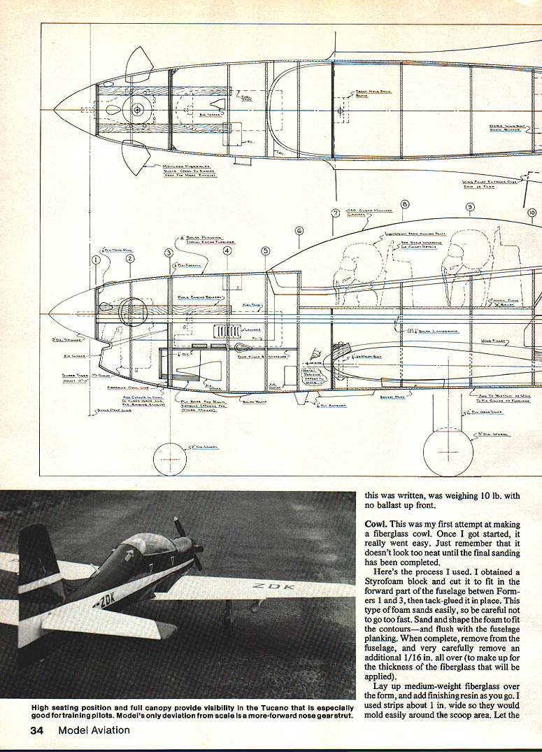
Cowl
This was my first attempt at making a fiberglass cowl. Once I got started, it really went easy. Just remember that it doesn't look too neat until the final sanding has been completed.
Here's the process I used. I obtained a Styrofoam block and cut it to fit in the forward part of the fuselage between Formers 1 and 3, then tack-glued it in place. This type of foam sands easily, so be careful not to go too fast. Sand and shape the foam to fit the contours—and flush with the fuselage planking. When complete, remove it from the fuselage, and very carefully remove an additional 1/16 in. all over (to make up for the thickness of the fiberglass that will be applied).
Lay up medium-weight fiberglass over the form, and add finishing resin as you go. I used strips about 1 in. wide so they would mold easily around the scoop area. Let the resin cure, remove the shell from the form, trim and sand the edges, fill any low spots with body filler, sand smooth and fit the cowl to the fuselage.
There you are: one fiberglass cowl. Later, you can cut the air intakes out and add other openings for the glow plug and exhaust as required. A very small cutout will be needed to clear the nose gear strut. Heated exhaust air will exit through the nose gear area.
Canopy
As with the cowl, there is no canopy that you can buy for this model. I had to learn how to form the clear plastic material into one. After I realized I had no other choice, I studied the problem for a while and found that this particular canopy design is relatively easy to make because the compound curving is very slight. You can make this canopy without use of a vacuum-former.
After reviewing several methods of making a canopy mold, I decided to just build it as part of the fuselage and cut it loose later for use. I made Formers 6 through 10 full-size and planked the canopy area at the time I was planking the rest of the fuselage. I tack-glued some 1/4 sq. balsa pieces along the top of the canopy floor and put in braces from side to side at each former. I cut through the formers along this line before completing the planking. If you plan it right, you can cut the canopy area loose as a separate unit after all the sanding and filling is complete. This unit is plenty strong for the purpose, as the hot plastic does not require a lot of pressure.
Make the surface as smooth as you can. Any bumps or seams in the planking will show up in the finished canopy. I applied two separate heavy coats of finishing resin and sanded the unit smooth, finishing with 400-grit wet sandpaper and 0000 steel wool.
Balsa USA sells plastic canopy material by the foot at a low cost. Buy enough for about three canopies; if you spoil one, you won't have to reorder and wait for it to arrive. I tacked the plastic to two pieces of hardwood about 1 in. sq., the length of the plastic. Place small tacks about 1 in. apart to keep the plastic straight (staples did not hold in the wood well enough). Cut the plastic about 3 in. longer than the canopy and about 3 in. less than your oven width.
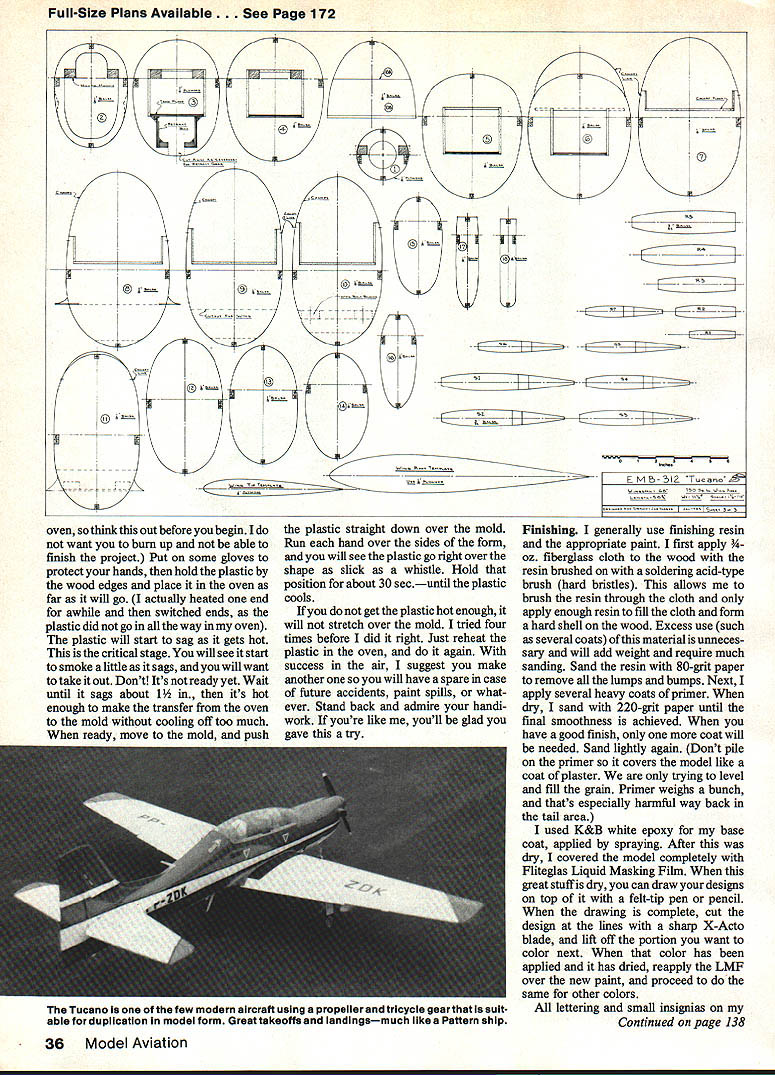
Arrange your form close to the oven on some object that will let your hands go down over the sides of the form. Set the oven at 450°F (mine is electric). Heat the plastic until it sags and then pull it down over the form with gloved hands. The plastic will take the shape in a few seconds. Be careful not to let it touch the oven elements. Allow the plastic to cool somewhat before removing the tacks, then carefully cut the part out and trim. Fit the canopy in place and sand the edges smooth. If you do not get the plastic hot enough, it will not stretch over the mold. I tried four times before I did it right. Just reheat the plastic in the oven, and do it again. Make another one so you will have a spare.
Finishing
I generally use finishing resin and appropriate paint. I first apply 3/4-oz. fiberglass cloth to the wood with the resin brushed on with a soldering-acid-type brush (hard bristles). This allows me to brush the resin through the cloth and only apply enough resin to fill the cloth and form a hard shell on the wood. Excessive use of this material is unnecessary and will add weight and require much sanding. Sand the resin with 80-grit paper to remove lumps and bumps. Next, apply several heavy coats of primer. When dry, sand with 220-grit paper until the final smoothness is achieved. When you have a good finish, only one more coat will be needed. Sand lightly again. (Don't pile on the primer to cover the model like a coat of plaster. We are only trying to level out the grain. Primer weighs a bunch, and that's especially harmful way back in the tail area.)
I used K&B white epoxy for my base coat, applied by spraying. After this was dry, I covered the model completely with Fliteglas Liquid Masking Film (LMF). When this great stuff is dry, you can draw your designs on top of it with a felt-tip pen or pencil. When the drawing is complete, cut the design at the lines with a sharp X-Acto blade, and lift off the portion you want to color next. When that color has been applied and dried, reapply the LMF over the new paint, and proceed to do the same for other colors.
All lettering and small insignias on my model were cut out of the LMF and then painted with a small brush. Using this method, you can get the correct scale of stars and bars, etc., and not have to use the closest-available size of decals. And you don't need to seal the painted-on items with a coat of clear as you do with decals. If you have to mix a special color, remember to keep a small amount of it for touch-ups which will probably be necessary later on.
Flying
In my past building and flying experiences, I have flown just about every popular model available. Yet, at the initial takeoff of each newly-completed model, I always have the "first flight jitters." This time was no different when the engine was running and the ship was sitting at the end of the McDonnell-Douglas club's asphalt runway.
The time comes when you have to do it, so I advanced the throttle. With power, the aircraft ran true down the runway and actually made a nice, slow takeoff all by itself. This was due to too much up-elevator trim. After the Tucano climbed to flight altitude, the only necessary trim was a bit of down-elevator. I flew the model around for about six laps of the field and prepared for the first landing. I lowered the retract gear and added about 25% flaps. With a new model, I like to limit the first flight to only the takeoff and landing. When I know it handles well in these crucial areas, my nerves relax a little, and I can turn my attention to various other maneuvers on following flights.
The Tucano landed just like my Curare, a Pattern airplane. I was, to say the least, quite impressed with what I had developed.
In subsequent flights, I found that due to the basic long moment arrangement, it flies as smoothly and nearly as responsively as my Pattern airplane. Landings are as flat and true, with no tendency to drop a wing tip even at extremely low landing speeds.
At the first three Sport Scale contests in which I entered the Tucano, the static points were right up with the other top models. Everyone who has seen it fly tells me they are impressed with the Tucano's looks in the air. What more could a modeler want?
Buy a big bag of balsa—and happy building!
Transcribed from original scans by AI. Minor OCR errors may remain.

