
Tutorn
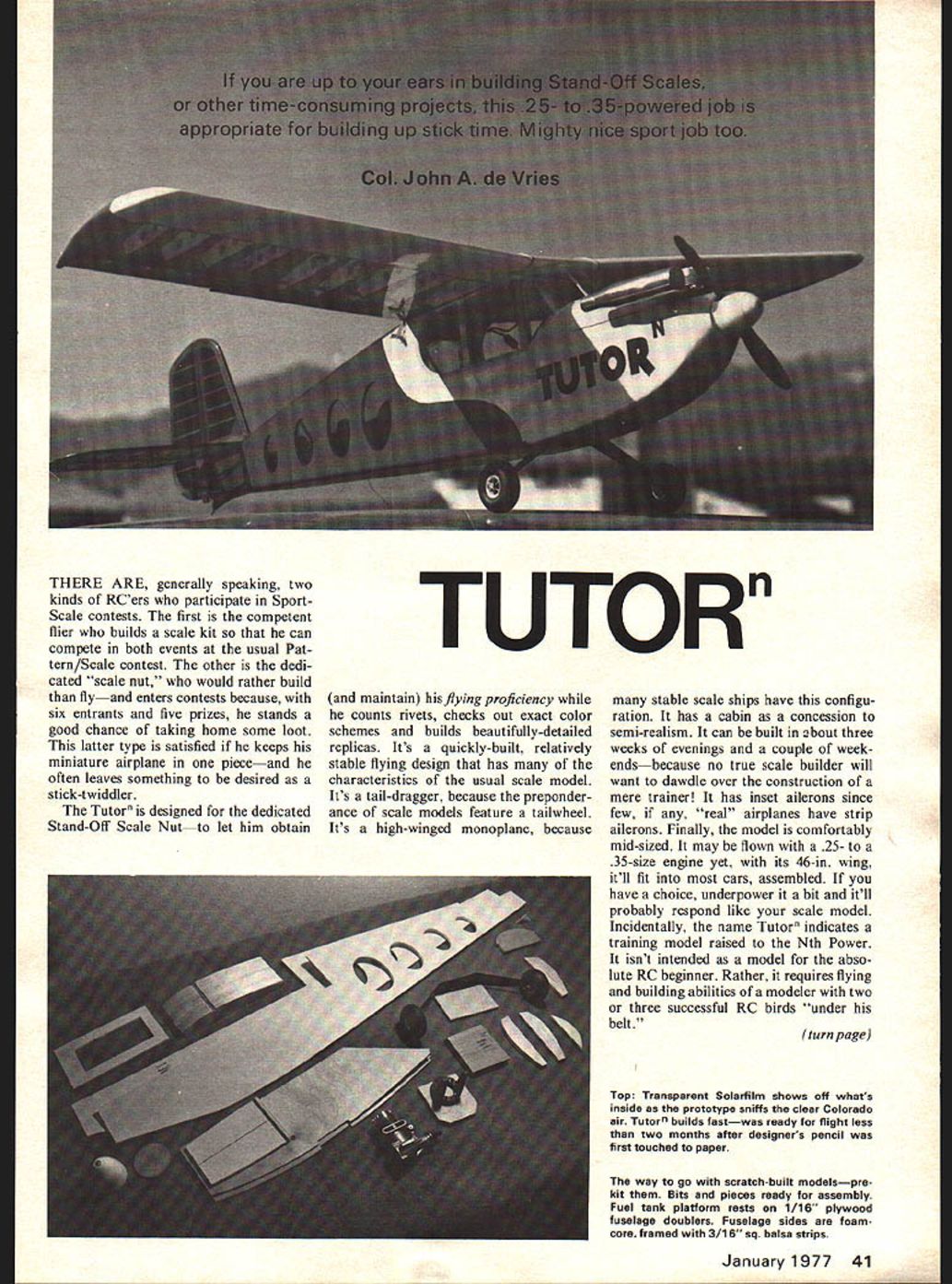
If you are up to your ears in building Stand-Off Scales, or other time-consuming projects, this .25- to .35-powered job is appropriate for building up stick time. Mighty nice sport job too.
Col. John A. de Vries
THERE ARE, generally speaking, two kinds of RC'ers who participate in Sport-Scale contests. The first is the competent flier who builds a scale kit so that he can compete in both events at the usual Pattern/Scale contest. The other is the dedicated "scale nut," who would rather build than fly—and enters contests because, with six entrants and five prizes, he stands a good chance of taking home some loot. This latter type is satisfied if he keeps his miniature airplane in one piece—and he often leaves something to be desired as a stick-twiddler.
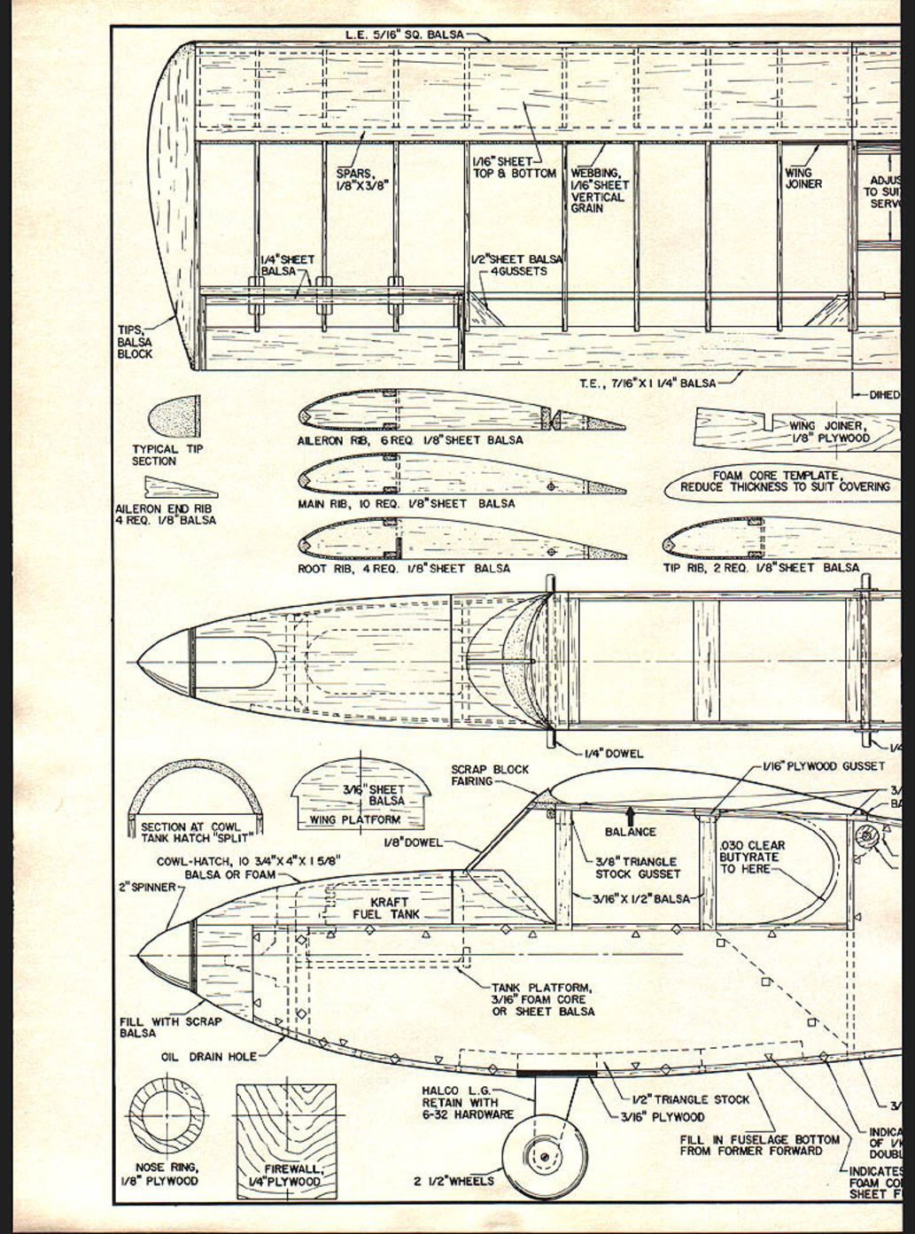
The Tutor is designed for the dedicated Stand-Off Scale Nut—to let him obtain (and maintain) his flying proficiency while he counts rivets, checks out exact color schemes and builds beautifully-detailed replicas. It's a quickly-built, relatively stable flying design that has many of the characteristics of the usual scale model. It's a tail-dragger, because the preponderance of scale models feature a tailwheel. It's a high-winged monoplane, because many stable scale ships have this configuration. It has a cabin as a concession to semi-realism. It can be built in about three weeks of evenings and a couple of weekends—because no true scale builder will want to dawdle over the construction of a mere trainer! It has inset ailerons since few, if any, "real" airplanes have strip ailerons. Finally, the model is comfortably mid-sized. It may be flown with a .25- to a .35-size engine yet, with its 46-in. wing, it'll fit into most cars, assembled. If you have a choice, underpower it a bit and it'll probably respond like your scale model. Incidentally, the name Tutor indicates a training model raised to the Nth Power. It isn't intended as a model for the absolute RC beginner. Rather, it requires flying and building abilities of a modeler with two or three successful RC birds "under his belt." (turn page) L.E., 5/16" sq. balsa
Spars, 1/8" x 3/8"
1/4" sheet balsa
1/16" sheet — top & bottom
Webbing, 1/16" sheet vertical grain
1/2" sheet balsa — 4 gussets
Wing joiner
Adjust to suit servos
T.E., 7/16" x 1 1/4" balsa
Typical tip section
Aileron end rib 4 req. 1/8" balsa
Aileron rib, 6 req. 1/8" sheet balsa
Main rib, 10 req. 1/8" sheet balsa
Root rib, 4 req. 1/8" sheet balsa
Tip rib, 2 req. 1/8" sheet balsa
Foam core template, reduce thickness to suit covering
1/4" dowel
Scrap block fairing
1/8" dowel
Balance
3/8" triangle stock gusset
3/16" x 1/2" balsa
0.030 clear butyrate to here
Cowl-hatch, 10 3/4" x 4" x 1 5/8" balsa or foam
Section at cowl tank hatch "split"
2" spinner
Kraft fuel tank
Tank platform, 3/16" foam core or sheet balsa
Fill with scrap balsa
Oil drain hole
Halco L.G. retain with 6-32 hardware
2 1/2" wheels
1/2" triangle stock
3/16" plywood
Fill in fuselage bottom from former forward
Nose ring, 1/8" plywood
Firewall, 1/4" plywood
TUTOR
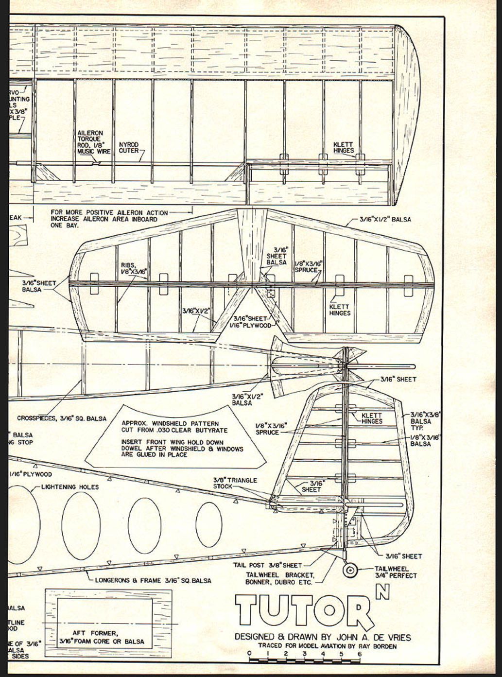
FOR MORE POSITIVE AILERON ACTION INCREASE AILERON AREA INBOARD ONE BAY.
AILERON TORQUE ROD, 1/8" MUSIC WIRE NYROD OUTER KLETT HINGES
RIBS, 1/8" x 3/16" 3/16" SHEET BALSA 3/16" x 1/2" BALSA 1/8" x 3/16" SPRUCE 3/16" SHEET / 1/16" PLYWOOD
3/16" x 3/8" BALSA TYP. 1/8" x 3/16" BALSA
3/8" TRIANGLE STOCK 3/16" SHEET
TAIL POST 3/8" SHEET TAILWHEEL BRACKET, BONNER, DUBRO, ETC. TAILWHEEL 3/4" PERFECT
LONGERONS & FRAME 3/16" SQ. BALSA CROSSPIECES, 3/16" SQ. BALSA
AFT FORMER, 3/16" FOAM CORE OR BALSA
DESIGNED & DRAWN BY JOHN A. DE VRIES TRACED FOR MODEL AVIATION BY RAY BORDEN
Construction
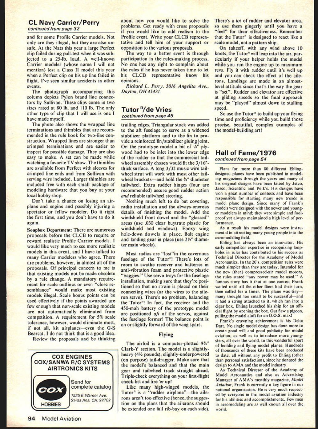
If you choose to go the foam wing route, the Tutor builds super-fast. The plans show ribs for both foam or built-up wings. We show the foam wing template full-sized — without any allowance for covering or planking. Thin it to the extent required for the material you intend to use (1/16" sheet balsa, plywood veneer, card). Inlet the 1/8" plywood "spar joiner" for center-section strength in a foam wing and don't forget to groove the foam cores for the aileron torque rods before you cover them. Aileron spars of 1/4" sheet balsa should be Titebonded in place to give the hinges an attachment area.
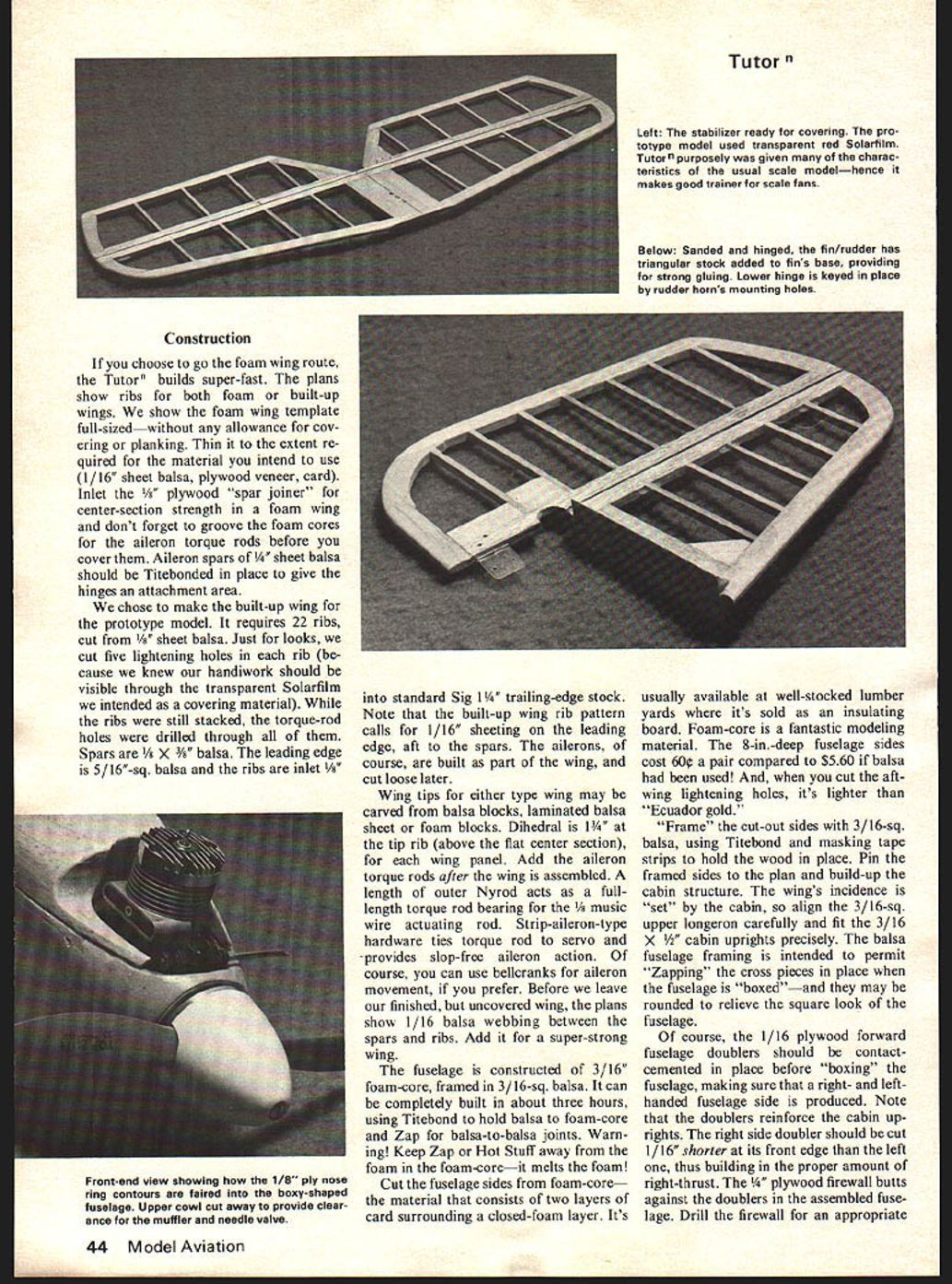
We chose to make the built-up wing for the prototype model. It requires 22 ribs, cut from 1/8" sheet balsa. Just for looks, we cut five lightening holes in each rib (because we knew our handiwork should be visible through the transparent Solarfilm we intended as a covering material). While the ribs were still stacked, the torque-rod holes were drilled through all of them. Spars are 1/8" x 3/16" balsa. The leading edge is 5/16"-sq. balsa and the ribs are inlet 1/8" into standard Sig 1 1/4" trailing-edge stock. Note that the built-up wing rib pattern calls for 1/16" sheeting on the leading edge, aft to the spars. The ailerons, of course, are built as part of the wing, and cut loose later.
Wing tips for either type wing may be carved from balsa blocks, laminated balsa sheet or foam blocks. Dihedral is 1 1/4" at the tip rib (above the flat center section), for each wing panel. Add the aileron torque rods after the wing is assembled. A length of outer Nyrod acts as a full-length torque rod bearing for the 1/8" music wire actuating rod. Strip-aileron-type hardware ties torque rod to servo and provides slop-free aileron action. Of course, you can use bellcranks for aileron movement, if you prefer. Before we leave our finished, but uncovered wing, the plans show 1/16" balsa webbing between the spars and ribs. Add it for a super-strong wing.
The fuselage is constructed of 3/16" foam-core, framed in 3/16"-sq. balsa. It can be completely built in about three hours, using Titebond to hold balsa to foam-core and Zap for balsa-to-balsa joints. Warning! Keep Zap or Hot Stuff away from the foam in the foam-core — it melts the foam!
Cut the fuselage sides from foam-core — the material that consists of two layers of card surrounding a closed-foam layer. It's usually available at well-stocked lumberyards where it's sold as an insulating board. Foam-core is a fantastic modeling material. The 8-in.-deep fuselage sides cost 60c a pair compared to $5.60 if balsa had been used! And, when you cut the aft-wing lightening holes, it's lighter than "Ecuador gold."
"Frame" the cut-out sides with 3/16"-sq. balsa, using Titebond and masking tape strips to hold the wood in place. Pin the framed sides to the plan and build-up the cabin structure. The wing incidence is "set" by the cabin, so align the 3/16"-sq. upper longeron carefully and fit the 3/16 x 1/4" cabin uprights precisely. The balsa fuselage framing is intended to permit "zapping" the cross pieces in place when the fuselage is "boxed" — and they may be rounded to relieve the square look of the fuselage.
Of course, the 1/16" plywood forward fuselage doublers should be contact-cemented in place before "boxing" the fuselage, making sure that a right- and left-handed fuselage side is produced. Note that the doublers reinforce the cabin uprights. The right side doubler should be cut 1/16" shorter at its front edge than the left one, thus building in the proper amount of right-thrust. The 1/8" plywood firewall butts against the doublers in the assembled fuselage. Drill the firewall for an appropriate Drill the firewall for an appropriate Kraft-Hayes (or other) engine mount and add blind nuts to its rear face. Do the same with the rectangular 3/16" ply landing gear mount — a Hallco landing gear (P/N B105-3) will be bolted to it later.
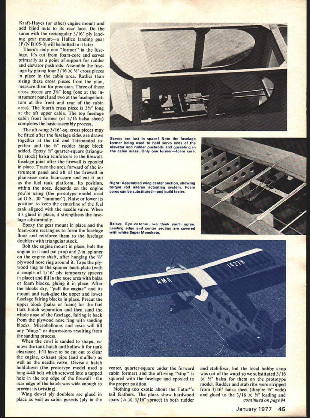
There's only one "former" in the fuselage. It's cut from foam-core and serves primarily as a point of support for rudder and elevator pushrods. Assemble the fuselage by gluing four 3/16 x 1/2" cross pieces in place in the cabin area. Rather than sizing these cross pieces from the plan, measure them for precision. Three of these cross pieces are 3 3/8" long (one at the instrument panel and two at the fuselage bottom at the front and rear of the cabin area). The fourth cross piece is 3 3/4" long at the aft upper cabin. The top fuselage cabin front former (of 3/16" balsa sheet) completes the basic assembly process.
The aft-wing 3/16"-sq. cross pieces may be fitted after the fuselage sides are drawn together at the tail and Titebonded together and the 3/8" rudder hinge block added. Epoxy 1/2" quarter-square (triangular stock) balsa reinforcers to the firewall-fuselage joint after the firewall is epoxied in place. Trace the area forward of the instrument panel and aft of the firewall in plan-view onto foam-core and cut it out as the fuel tank platform. Its position, within the nose, depends on the engine you're using (the prototype model used an O.S. .30 "hummer"). Raise or lower its position to keep the centerline of the fuel tank aligned with the needle valve. When it's glued in place, it strengthens the fuselage substantially.
Epoxy the gear mount in place and the foam-core rectangles to form the fuselage floor and reinforce them to the fuselage doublers with triangular stock.
Bolt the engine mount in place, bolt the engine to it and put prop and 2-in. spinner on the engine shaft, after hanging the 1/8" plywood nose ring around it. Tape the plywood ring to the spinner back-plate (with a couple of 1/16" ply temporary spacers in place) and fill in the nose area with balsa or foam blocks, gluing it in place. After the blocks dry, "pull the engine" and its mount and tack-glue the upper and lower fuselage fairing blocks in place. Precut the upper block (balsa or foam) for the fuel tank hatch separation and then sand the whole nose of the fuselage, fairing it back from the plywood nose ring with sanding blocks. Microballoons and resin will fill any "dings" or depressions resulting from the sanding process.
When the cowl is sanded to shape, remove the tank hatch and hollow it for tank clearance. It'll have to be cut out to clear the engine, exhaust pipe (and muffler) as well as the needle valve. Devise a hatch hold-down (the prototype model used a long 4-40 bolt which screwed into a tapped hole in the top edge of the firewall — the rear edge of the hatch was wide enough to prevent its twisting).
Wing dowel ply doublers are glued in place as well as cabin gussets (ply in the center, quarter-square under the forward cabin former) and the aft-wing "stop" is squared with the fuselage and epoxied to the proper position.
Nothing too exotic about the Tutor's tail feathers. The plans show hardwood spars (1/8 x 3/16" spruce) in both rudder and stabilizer, but the local hobby shop was out of the wood so we substituted 3/16 x 1/2" balsa for them on the prototype model. Rudder and stab ribs were stripped from 3/16" balsa sheet (they're 3/8" wide) and glued to the 3/16 x 1/2" leading and
Tutor / de Vries
trailing edges. Triangular stock was added to the aft fuselage to serve as a widened stabilizer platform and to the fin to provide a reinforced fin/stabilizer gluing joint. On the prototype model a bit of 1/8" plywood had to be inletted into the lower edge of the rudder so that the commercial tailwheel assembly chosen would fit the 3/16" thick surface. A long 3/32" music wire tailwheel strut will work with most other tailwheel brackets — and hold the 1/4" diameter tailwheel. Extra rudder hinges (four are recommended) assure good rudder action and reliable tailwheel steering.
Nothing much left to do but covering, radio installation and the always onerous details of finishing the model. Add the windshield front dowel and the "glassed" areas (use .030 clear butyrate plastic for windshield and windows). Epoxy hold-down dowels in place. Bolt engine and landing gear in place (use 2 1/2" diameter main wheels).
Most radios are "lost" in the cavernous fuselage of the Tutor! There's lots of room to swathe receiver and batteries in anti-vibration foam and protective plastic "baggies." Use servo trays for the fuselage installation, making sure that they're positioned so that no strain is placed on their connecting wires (or the wires to the aileron servo). There's no problem balancing the Tutor! In fact, the receiver and the 450-mah battery of the prototype model are positioned aft of the servos, against the fuselage former. The balance point is on or slightly forward of the wing spars.
Flying
The airfoil is a computer-plotted 9 3/4" Clark-Y section. The model is a slightly-heavy (4 1/2 pounds), slightly-underpowered (on purpose) tail-dragger. Make sure that the model is balanced and that the main gear and tailwheel track straight ahead. Triple-check everything on your first-flight check-list and fire 'er up!
Like many high-winged models, the Tutor is a "rudder airplane" — the ailerons aren't too effective (hence, the suggestion on the plans that the ailerons should be extended one full rib-bay on each side).
There's a lot of rudder and elevator area, so use them gingerly until you have a "feel" for their effectiveness. Remember that the Tutor is designed to react like a scale model, not a pattern ship.
On takeoff, with any wind above 10 knots, the Tutor will leap into the air, particularly if your helper holds the model while you run the engine up to maximum revs. Fly it with rudder until it's well up and you can check the effect of the ailerons. Landings are made in an almost-level attitude since that's the way the gear is "set". Rudder and elevator are effective at gliding speeds so the final approach may be "played" almost down to stalling speed.
So use the Tutor to build up your flying time and proficiency while you build those precise, beautiful, complex examples of the model-building art!
Transcribed from original scans by AI. Minor OCR errors may remain.

