
Twin Comanche
Do you have two .25 engines that you'd like to put to good use? Put them in this CL Sport Scale model (or add more details for CL Precision Scale), and get ready to pick up some contest "hardware."
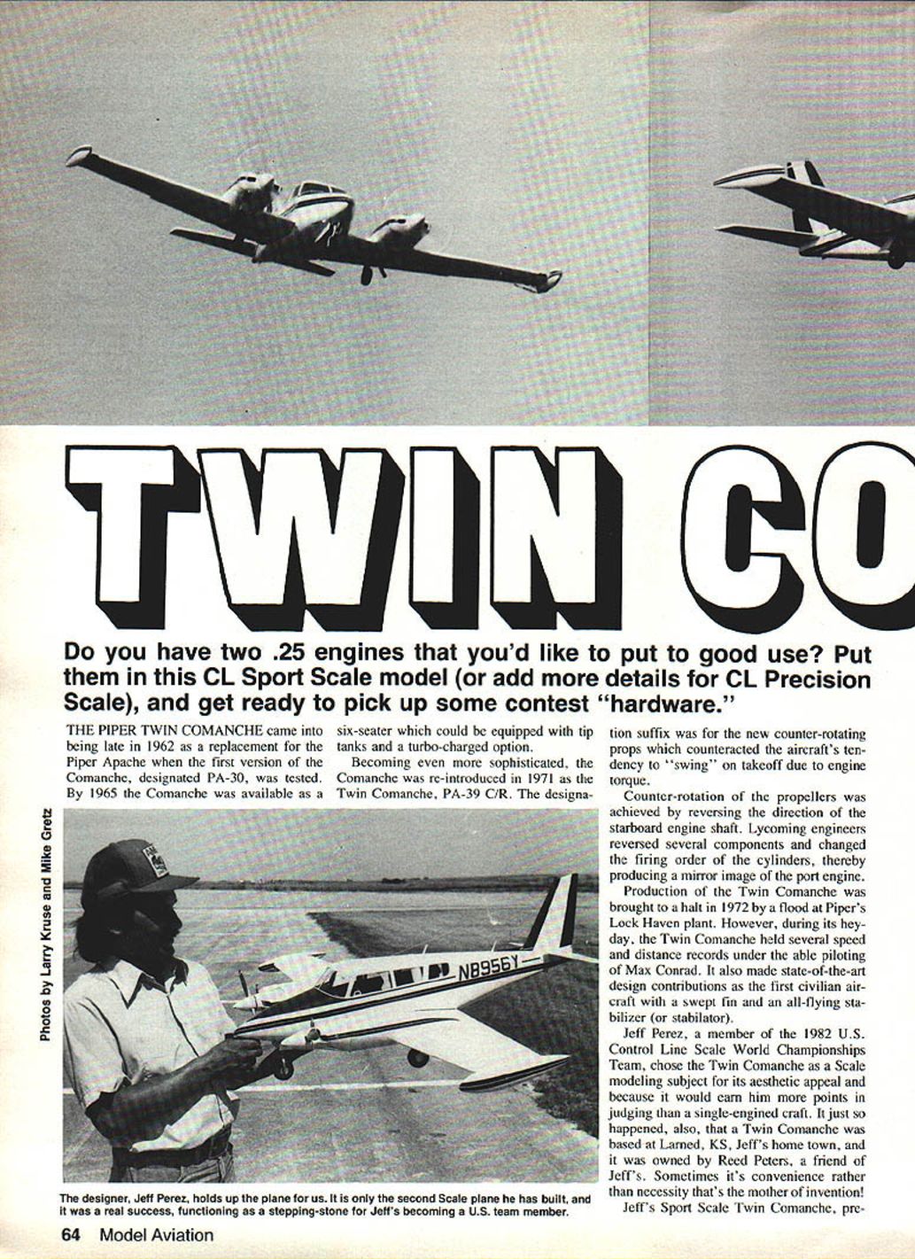
The Piper Twin Comanche originated in late 1962 as a replacement for the Apache when the PA‑30 Comanche first appeared. By 1965 the Comanche was available as a six‑seater with optional tip tanks and turbocharging. Reintroduced in 1971 as the Twin Comanche PA‑39 C/R, the suffix denoted counter‑rotating props that counteracted the aircraft's tendency to swing on takeoff due to engine torque. Lycoming achieved counter‑rotation by reversing the starboard engine shaft and altering several internal components and the firing order to produce a mirror image of the port engine.
Production was halted in 1972 by a flood at Piper's Lock Haven plant. During its heyday, the Twin Comanche set several speed and distance records with Max Conrad at the controls and introduced state‑of‑the‑art features such as a swept fin and an all‑flying stabilizer (stabilator).
Model overview
Jeff Perez, a member of the 1982 U.S. Control Line Scale World Championships Team, chose the Twin Comanche for its aesthetic appeal and the contest bonus points awarded to twin‑engined aircraft. A full‑size Twin Comanche was based in Larned, KS, Jeff's hometown, and was owned by his friend Reed Peters — a convenient resource for reference.
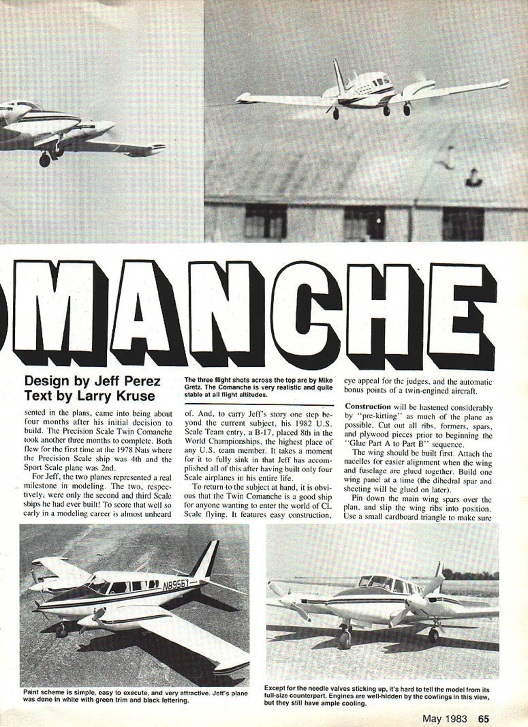
Jeff built a Sport Scale Twin Comanche (plans shown) about four months after deciding to build; the Precision Scale version took an additional three months. Both flew for the first time at the 1978 Nats: the Precision Scale ship placed 4th and the Sport Scale plane 2nd. These were only the second and third scale ships Jeff had built — remarkable contest results early in his modeling career. Jeff later flew a B‑17 for the 1982 U.S. Scale Team and placed 8th in the World Championships.
The Twin Comanche is a good entry into CL Scale flying: relatively easy construction, strong eye appeal, and the twin‑engine bonus in judging. Construction will be much faster if you pre‑kit: cut all ribs, formers, spars, and plywood pieces before beginning assembly.
Construction
Wing
- Build one wing panel at a time. The dihedral spar and sheeting are glued on later.
- Pin down the main spars over the plan and slip the ribs into position.
- Use a small cardboard triangle to ensure ribs are perpendicular to the spars.
- Tack‑glue ribs temporarily with a drop of a thicker cyanoacrylate (CyA) such as Super Jet or Zap‑A‑Gap.
- Slip the trailing‑edge spar into the rib notches and glue; note the spar laps over itself at Rib Station 6.
- Install the leading edge piece.
- Constantly check alignment. If a rib needs repositioning, pop it off and realign — twisted wings fly poorly.
- When satisfied, glue ribs permanently with CyA.
- Add tapered trailing‑edge pieces and tip blocks.
- Use the tip‑rib template to gouge out openings in wing tank blocks before carving.
- After both panels reach this stage, join them with the dihedral spar epoxied in place.
Nacelles, landing gear and dihedral
- Attach nacelles to the wing for easier alignment when mating wing and fuselage; epoxy them to the leading edge and main spar and check alignment as the assembly cures.
- Main landing gear legs are bent from 5/32‑in. wire and J‑bolted to the spar at the shown locations. Adjust as needed so wheels track parallel.
- The plans show a Sport Scale gear; for Precision Scale, Jeff machined the front landing‑gear fork from key stock and attached it with a setscrew. He made two L‑shaped brackets for the main gear the same way.
Bellcrank and throttle controls
- Drill mounting holes and temporarily mount engines and tanks to verify no thrust offset is required.
- Epoxy the bellcrank platform and bolt on the Roberts upright bellcrank.
- Route a braided cable (Gold 'N Rod) with its plastic casing through the wing rib and spar structure and through each nacelle for dual throttle controls.
- Attach a 1/16‑in. music‑wire pushrod, wrapped and soldered to the braided cable, to the throttle arm of the bellcrank. You may need to drill slightly inside the original third‑line location to attach the pushrod.
- Since both engines use the same throttle cable, position carburetor control horns opposite each other so both engines have correct high/low settings.
- Check for binding or interference, especially muffler interference with the carburetor horn or pushrod in the up position.
Wing sheeting and cowls
- After lead‑outs are strung from the bellcrank, sheet the wing with 1/16‑in. balsa.
- Plank nacelle areas and fill small gaps with balsa blocks as needed.
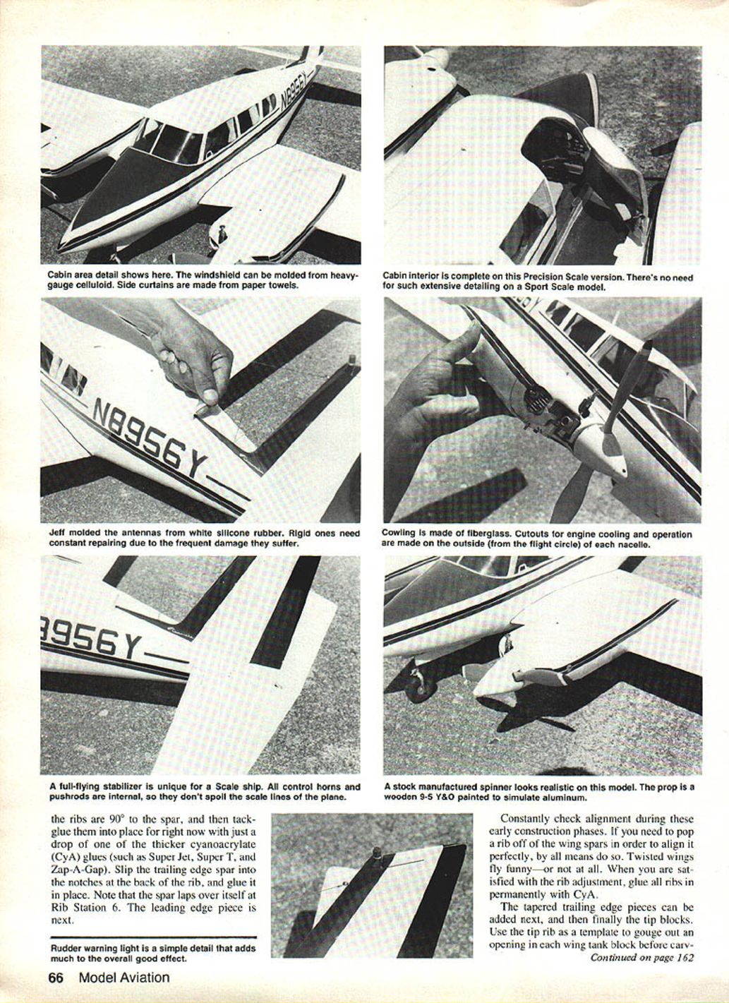
- Cowls can be made from fiberglass laid up over carved forms using the "balloon" molding method.
Stabilizer and rudder
- Cut stabilizer and rudder from 1/8‑in. sheet and sand to airfoil shape.
- The stabilizer must be mounted as a unit with its maple bearing block. Reinforce the rear of the stab with plywood doublers where shown.
- Drill the mounting block for a 5/32‑in. I.D. brass tube to serve as a bushing for the 5/32‑in. music‑wire control horn. Solder the horn to the music wire, slip through the maple bushing, and bend the horn "arms" to shape.
- Slot the bottom of the stab for the control‑horn wire and fill with microballoons and epoxy for strength. Set the stab assembly aside until fuselage installation.
- The rudder needs minimal work beyond sanding. A simulated rudder light made from red Lucite and fitted with an aluminum tube ring at its base enhances scale appearance.
Fuselage
- The fuselage is a keel, crutch, and former assembly. Build a simple jig to aid construction: a plywood base (1/2‑in. or 1/4‑in., length about that of the fuselage, width ~6 in.) with scribed former locations and vertical former holders (1/4 × 3/4‑in. plywood).
- Cut a 1/4‑in. slot at the center of each former holder to allow keel clearance.
- Mount the nose gear to Former A before installing the keel and crutch.
- Use rubber cement to tack formers to the jig, repositioning as needed for alignment during keel/crutch installation.
- Cover the fuselage with 1/8 × 3/16‑in. balsa planking; wider strips may be used on nearly flat top and bottom areas.
- Soak planking strips in hot water with a little ammonia to increase pliability for nose curves.
- Plank using alternating strips (one side, then the opposite) to avoid pulling the fuselage off center or inducing twist. Continuously check alignment.
- As planking proceeds, cut openings for wing and stabilizer mounts when the structure is strong enough to handle without misalignment.
- Epoxy wing and stabilizer in place, checking their relative positions and fuselage alignment. Hook up the stab pushrod and adjust its length for a neutral stabilizer when the bellcrank is neutral.
Windows and cabin
- After planking, cut window openings and temporarily fit celluloid.
- Install a soft balsa block in the windshield area, carve to shape, and use it as a mold for the actual windshield (heavy‑gauge clear plastic can be heated and draped over the carved block).
- Trim and glue the molded windshield, sealing edges with latex rubber.
- Cabin side curtains can be simulated with paper towels glued and painted inside the cabin. The instrument panel can be cut from thin plywood and painted.
- For Sport Scale models, extensive interior detailing is unnecessary.
Finishing and detailing
- Sand the entire model carefully. Fill fillets and gaps with Sig Epoxolite or polyester resin with microballoons, or use vinyl spackling (e.g., DAP) for pits and cracks.
- Apply a thin coat of Hobbypoxy Quick Prep Resin and let cure. Scuff‑sand, then apply a second thin coat. Scuff‑sand the second coat with 320‑grit paper.
- While the second coat is still tacky, apply silk or silkspan (Jeff used silk in high‑strength areas and silkspan on large flats). Tack down any unstuck edges and let cure.
- Brush on a third coat of resin without sanding; wet‑sand with 150–200‑grit, then add a fourth coat. Wet‑sand with 320‑grit and spray a light primer coat.
- Jeff used automotive enamel and primer; if you use Hobbypoxy or K&B Super Poxy, use their recommended primers for compatibility.
- Wet‑sand primer with 400‑grit and spray the white base coat in light applications to build a smooth surface for trim colors. Be careful removing masking tape—underlying resin can lift paint.
- Rub out the final finish with rubbing compound and apply several coats of automotive wax.
- Add windows, windshield, landing‑gear doors, and trim. Mold antennas from silicone rubber to reduce breakage and attach to the fuselage. Side curtains can be suggested with folded paper towels. Logos were hand‑painted and "No Step" warnings applied with press type letters.
Flying
- A properly built Twin Comanche will be light and easy to manage, but single‑engine performance is marginal; synchronize both engines by ear before the first flight.
- Twin engines produce an attractive sound and tend to draw a crowd. Good luck with your Twin Comanche.
Reference Sources
- Francis, Devon. Mr. Piper and His Cubs. Iowa State University Press, Ames, IA, 1976, pp. 178, 179, 188, 194, 195, 202.
- Jane’s All The World’s Aircraft 1972–73. John R. Taylor, ed., McGraw‑Hill Book Company, New York, NY, p. 406.
- Jane’s All The World’s Aircraft 1973–74. John R. Taylor, ed., McGraw‑Hill Book Company, New York, NY, pp. 409–410.
- Jane’s Encyclopedia of Aviation—Vol. 5. M. J. H. Taylor, ed., Grolier and Company, Danbury, CT, 1980, pp. 896, 898.
Transcribed from original scans by AI. Minor OCR errors may remain.

