
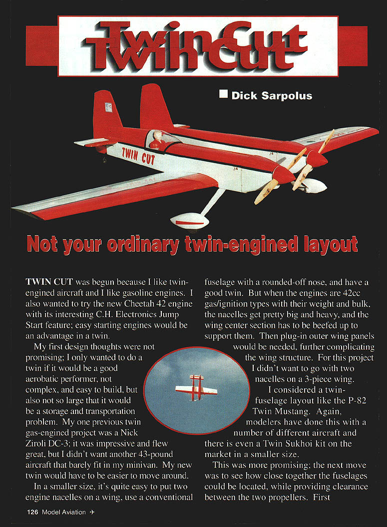

Twin Cut: Not your ordinary twin-engined layout
Dick Sarpolus
TWIN CUT was begun because I like twin-engined aircraft and I like gasoline engines. I also wanted to try the new Cheetah .42 engine with its interesting C&H Electronics Jump Start feature; easy-starting engines would be an advantage in a twin.
My first design thoughts were not promising; I only wanted to do a twin if it would be a good aerobatic performer, not complex, and easy to build, but also not so large that it would be a storage and transportation problem. My one previous twin gas-engined project was a Nick Ziroli DC-3; it was impressive and flew great, but I didn't want another 43-pound aircraft that barely fit in my minivan. My new twin would have to be easier to move around.
In a smaller size, it's easy to put two engine nacelles on a wing and use a conventional fuselage, but with 42cc gas/ignition engines the nacelles get large and heavy and the wing center section must be beefed up. That typically requires plug-in outer wing panels and a more complex wing structure — something I wanted to avoid.
I considered a twin-fuselage layout like the P-82 Twin Mustang. Modelers have done this many times, and there are kits in smaller sizes. I then explored how close the fuselages could be while allowing propeller clearance. Initial calculations showed the aircraft would still be larger than I wanted.
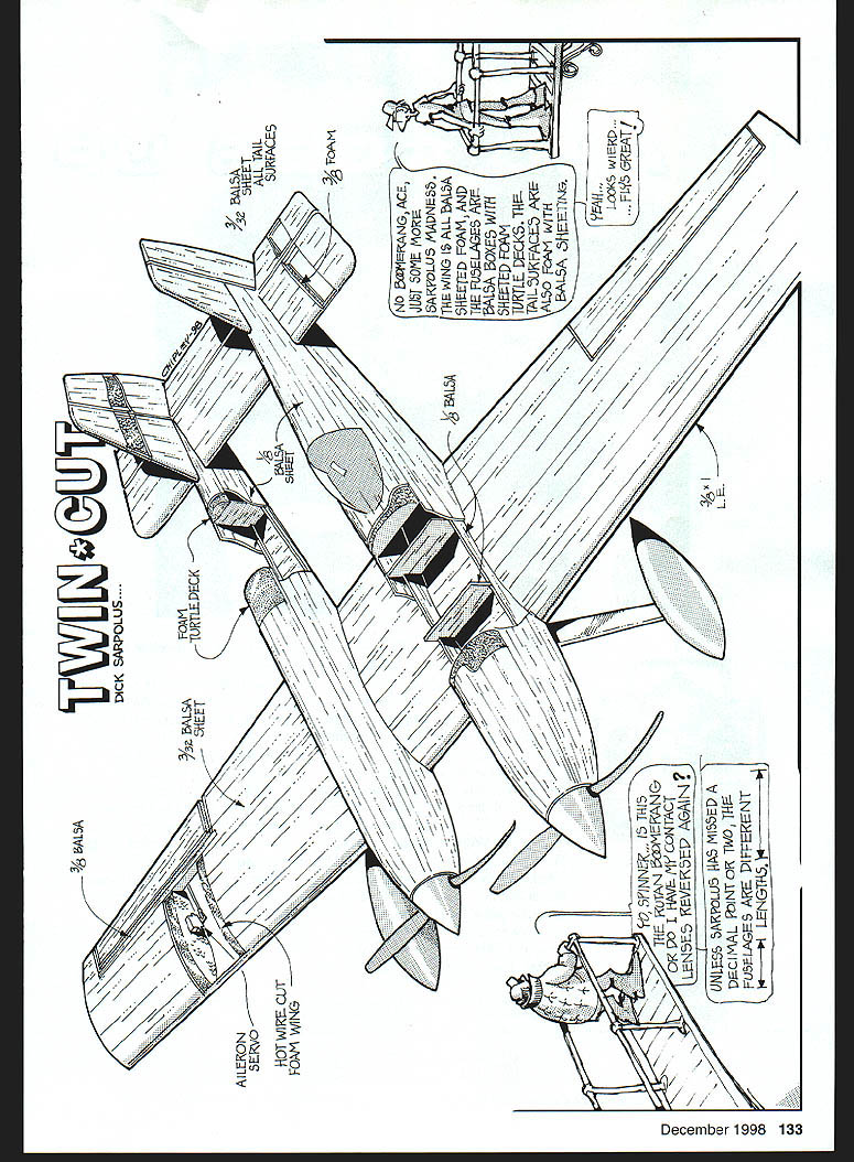
Then another idea: what if one engine was located behind the other, the fuselages moved closer together, and the propellers permitted to overlap? This has been done before (an experimental twin Cub) and Rutan has used overlapping prop ideas on his asymmetrical designs. I also realized the fuselages could be different — only one needs a cockpit — giving a somewhat radical racing/aerobatic appearance.
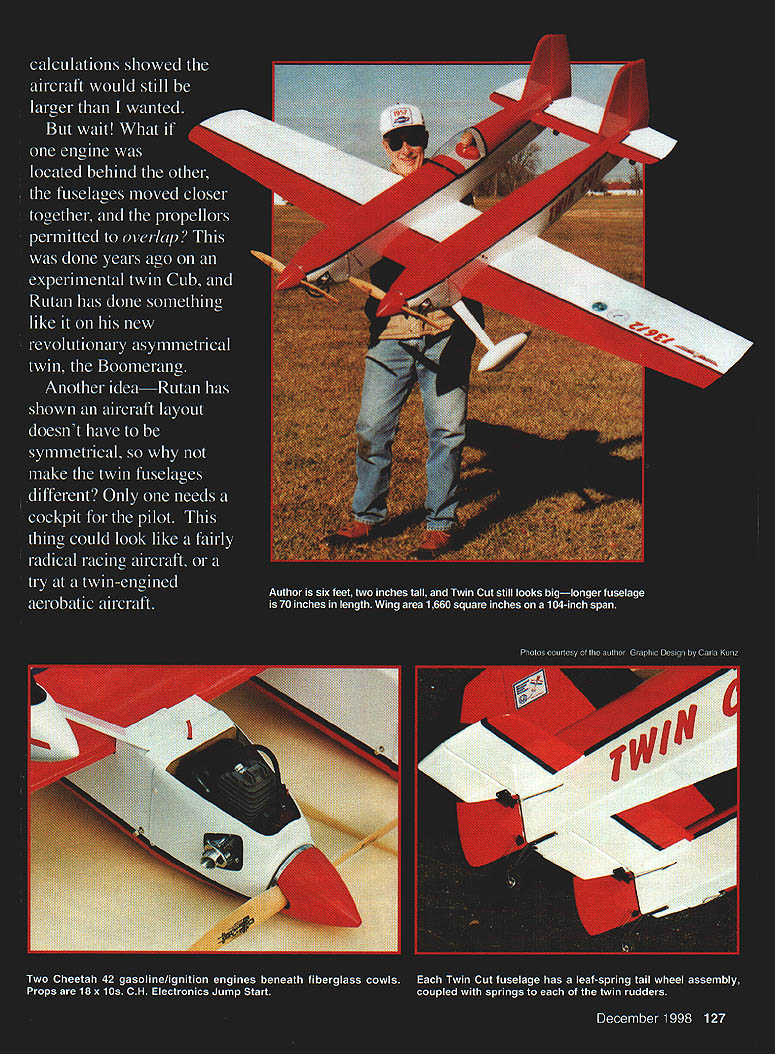
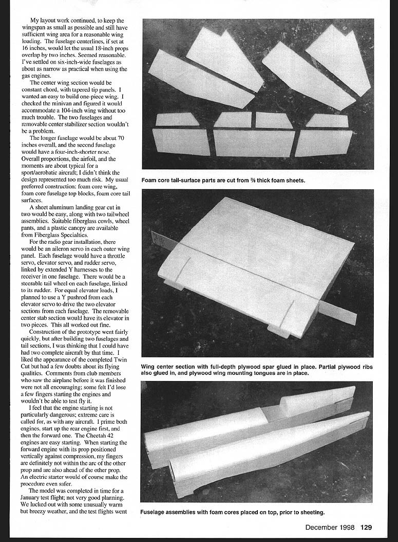
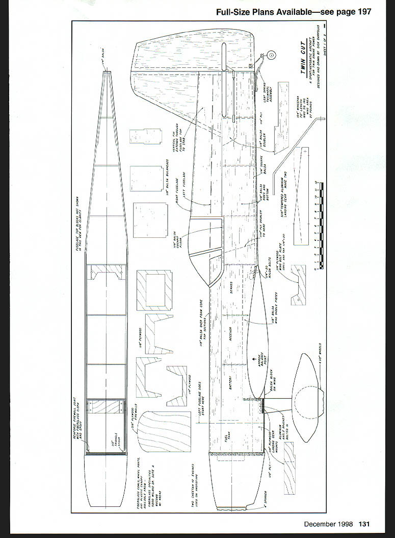
Layout choices settled on keeping wingspan small but with sufficient wing area for reasonable wing loading. Fuselage centerlines at 16 inches allowed standard 18-inch props to overlap by about 2 inches. Fuselage width settled at about 6 inches as the narrowest practical when using gas engines. The center wing section would be constant chord with tapered tip panels for an easy one-piece wing. I checked my minivan and figured a 104-inch wing would fit without too much trouble. The longer fuselage is about 70 inches overall; the second fuselage has a nose 4 inches shorter. My preferred construction methods were foam-core wing and fuselage top blocks, foam-core tail surfaces, and sheet-aluminum landing gear. Fiberglass cowls, wheel pants, and a plastic canopy are available from Fiberglass Specialties.
For radio installation I planned:
- An aileron servo in each outer wing panel.
- Each fuselage to have a throttle servo, elevator servo, and rudder servo, linked by extended Y-harnesses to the receiver in one fuselage.
- A steerable tailwheel on each fuselage, linked to its rudder.
- A Y pushrod from each elevator servo to drive the two elevator sections (removable center stab has its elevator in two pieces).
After building the two fuselages and tail sections the prototype went together fairly quickly. Some club members were skeptical about engine-starting safety, but with care I found starting manageable: I prime both engines, start the rear engine first, then the forward one. The Cheetah .42s are easy to start, and using an electric starter would make the procedure even safer.
The model was completed in time for winter test flights. Warm, breezy conditions allowed successful initial flights: the Twin Cut flew smooth and steady with plenty of power from the two Cheetahs. Rolls and loops responded quickly and positively; the two-fuselage configuration did not hinder aerobatic performance. After initial flights that included loops, rolls, snaps, spins, stall turns, and low inverted passes, I was confident the design was capable of competition-class maneuvers. Twin Cut was stable, easy to fly (almost like a single-engine aircraft) and delivered the twin-engine sound I had hoped for.
Construction
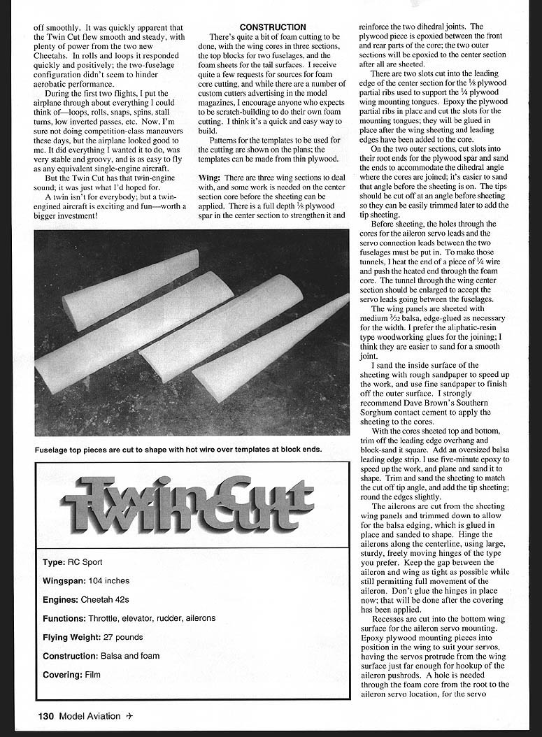
There's a fair amount of foam cutting to be done: wing cores in three sections, top blocks for the two fuselages, and foam sheets for the tail surfaces. While there are custom foam cutters advertised, I encourage scratch-builders to cut their own foam — it's quick and easy. Patterns and templates are shown on the plans; templates can be made from thin plywood.
Wing
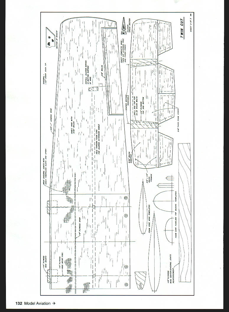
- The wing is built in three sections: a one-piece center section and two outer tip panels.
- The center-section core receives a full-depth 3/8-inch plywood spar to strengthen it and reinforce the dihedral joints.
- Two slots are cut into the leading edge of the center section to accept 1/4 plywood partial ribs that support the 1/4 plywood wing-mounting tongues. Epoxy the partial ribs in place and cut the slots for the mounting tongues; the tongues are glued in after wing sheeting and leading edges are added.
- On the outer sections, cut slots at the root for the plywood spar and sand the root ends to accommodate the dihedral angle before sheeting. Tip ends should be cut at an angle before sheeting to simplify later trimming and adding tip sheeting.
- Make tunnels through the cores for servo leads and for servo-extension cables between fuselages. I heat the end of a 1/4" wire or rod and push it through the foam to form the tunnels; enlarge the center-section tunnel for the elevator/servo leads.
- Sheet the wing panels with medium 3/32" balsa, edge-glued as necessary. I prefer aliphatic-resin woodworking glues for joining and Dave Brown's Southern Sorghum contact cement for applying sheeting to the cores.
- After the cores are sheeted top and bottom, trim the leading-edge overhang, block-sand it square, and add an oversized balsa leading edge strip glued with five-minute epoxy. Plane and sand to shape, then attach tip sheeting and slightly round the edges.
- Cut the ailerons from the sheeting panel and fit balsa edging. Hinge the ailerons along the centerline using sturdy hinges, keeping the gap tight but ensuring full movement. Do not glue hinges in until after covering.
- Recesses for aileron servos are cut into the bottom wing surface. Epoxy plywood mounting plates in place so servos protrude slightly for pushrod hookup. Run a hole through the foam core from the root to the aileron servo for the wires.
- When joining wing panels, use 1-1/2 inches of dihedral under each wingtip. Epoxy panels together, sliding tip panels over dihedral braces. Wrap the dihedral joints with heavy fiberglass cloth and epoxy (I used 12" wide cloth around each joint) and add a 6" strip of cloth around the center-section leading edge between fuselages for extra strength. Brush on slow epoxy, position cloth, saturate, and squeeze off excess with cardboard for a smooth, lightweight finish.
Fuselages
- The fuselages are basically the same except the left fuselage has a 4-inch shorter nose. Select firm-to-hard balsa for sides and edge-glue/splice as needed.
- Glue 1/4" plywood doublers, landing gear mount doublers, balsa wing-saddle pieces, stab saddle doublers, and balsa rear lower edge strips to the fuselage sides. Firewalls are 3/8" plywood laminated from 3/16" and 1/8" sheets.
- With one fuselage side flat, add the firewall and the next four bulkheads at right angles, then glue the second side to those bulkheads. Add triangle stock and heavy fiberglass cloth behind the firewall to reinforce the joint; I also used small screws through the firewall into the sides.
- Add the 1/4" plywood wing-bolt plate and 1/4" plywood landing gear mount, then close the tail end installing rear bulkheads. Ensure fuselage sides taper straight to the rear so straight-cut foam top blocks fit correctly.
- Trial-fit and trim the rear top block as you install bulkheads so the block fits well; sand block edges as needed before sheeting. Sheet the top foam blocks as with the wing cores, then glue the top blocks to the fuselages. I used a higher rear top block and plastic canopy on the right fuselage and a low top block on the left for asymmetry.
- Reinforce the plywood landing gear mount from inside with hardwood blocks where holes will be drilled and tapped for nylon gear-retaining bolts. I also use an aluminum right-angle bracket on each side of the gear mount, bolting it to the gear mount and through the fuselage sides. With this size aircraft I prefer extra mechanical fastening so that the nylon retaining bolts break instead of pulling out wood in a rough landing.
- Engines are mounted on a 3/4" thick plywood spacer ring to provide clearance for stock Cheetah mufflers. I use 10-32 Allen bolts through the engine mount with blind nuts on the rear side of the firewall so the engine can be removed from the front without accessing the fuselage interior.
- After engine mounting and drilling firewall holes for fuel tubing, throttle linkage, and ignition wiring, glue the plywood forward bottom piece to the fuselage, round the lower front corners, and trim fiberglass cowls to fit. Leave the rear fuselage bottom planking off until tail surfaces are added so holes for elevator and rudder pushrods can be cut in the rear bulkheads.
- For servo installation I use 1/4" plywood mounts in the fuselages and fiberglass-tube pushrods for elevators and rudders. All pushrod hardware is 4-40 threaded rods and clevises. Color-code servo leads and extension cables with paint dots to simplify hookup when assembling the aircraft. A 1,200 mAh battery pack wrapped in foam was used in the prototype.
Tail Surfaces
- Tail parts are built from 3/8" thick foam sheets edged with 3/8" by 1/2" balsa and sheeted with 3/32" balsa as with the wing cores.
- The horizontal stabilizer is made in three pieces so the center section is easily installed and removed. 1/8" plywood tabs on top and bottom of the fixed stab accept the removable center section; two 10-32 nylon bolts on each side retain the center section. Hardwood blocks are installed in the center-section ends where the nylon bolts pass.
- Elevators are in four sections (two per side) with the two elevators on each side driven by one elevator servo in each fuselage via a Y pushrod. Cut hinge slots or drill holes along center lines as required by your hinge type and notch control surfaces for a close fit while allowing full movement.
- Use 1/4" plywood pads for control-horn mounting, recessed and epoxied into elevators and rudders. Mount horns with self-tapping screws.
- Each fuselage has a leaf-spring tailwheel assembly mounted on 1/8" plywood in the fuselage bottom and linked to its rudder by coil springs. There is a rudder servo and a throttle servo in each fuselage. Servo-extension cables through the wing center section connect elevator, rudder, and throttle servos via Y-harnesses to the receiver (installed in one fuselage).
- Fit the fuselages to the wing, adjust wing-mounting tongues and drill/tap wing-mount plates for two 1/4-20 nylon bolts holding each fuselage. Adjust the two fuselages so the horizontal stabilizer will be parallel to the wing center section.
- With the wing mounted, bolt the horizontal stab up as one piece and glue the outer stab sections to the fuselages so the center section remains removable and sits precisely in place. Add vertical fins perpendicular to the stabilizer.
Landing Gear and Finishing
- A conventional sheet-aluminum landing gear can be cut in two and used on each fuselage. I also tried a molded epoxy composite gear made by a fellow modeler, cut in half and held with four 1/4-20 nylon bolts per leg.
- Four-inch spinners (CB units) and fiberglass wheel pants mounted with nylon brackets were used.
- I covered the model with iron-on plastic film and added vinyl lettering for name and AMA number. Fiberglass cowl and wheel pants were spray-painted.
Ignition and Starting
- The C&H Electronics Jump Start ignition module is carried in the aircraft; an external battery pack is plugged into a jack on the fuselage side only for starting. With the switch in the start position the module provides spark timing for easy, safe starting. Once running, flip the switch to run, unplug the battery pack, and the engine continues on its magneto.
- My starting procedure: prime both engines, start the rear engine first, then the forward engine. With care the procedure is safe; fingers are kept clear of prop arcs. An electric starter would make starting even safer.
- Before first flights adjust each carburetor for reliable idle and slightly rich top end while engines are new. Use a tach to get both engines roughly the same speed, but exact synchronization is not critical — reliable operation is far more important.
Flying
- On first flights the Twin Cut flew smoothly with plenty of power from the two Cheetah .42s turning 18x10 props. I flew rolls, loops, snaps, spins, stall turns, and low inverted passes — the airplane handled all maneuvers positively and responsively.
- The two-fuselage configuration did not hinder aerobatic performance. The model was stable, easy to fly (the feel was equivalent to a single-engine aircraft), and produced the twin-engine sound I wanted.
- Twin-engined aircraft are not for everybody, but they are exciting and fun and worth the bigger investment if you enjoy the characteristics they bring.
Dick Sarpolus 32 Alameda Ct Shrewsbury, NJ 07702
Transcribed from original scans by AI. Minor OCR errors may remain.

