
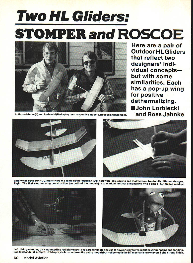
Two HL Gliders: Stomper and Roscoe
John Lorbiecki and Ross Jahnke
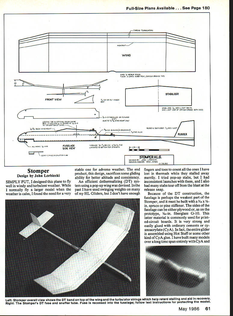
Stomper Design — John Lorbiecki
Simply put, the Stomper is designed to fly well in windy, turbulent weather. While I normally fly a larger model when the weather is calm, I found the need for a very stable model in adverse weather. The design sacrifices some gliding ability for better altitude consistency.
An efficient dethermalizing (DT) system using a pop-up wing was devised because swinging weights are unreliable on HL (half-length) gliders — they lack sufficient mass and have led to lost thermals and stalls. Pop-up stabilizers were tried but caused inconsistent launches and sometimes tore off at the blast-release snap.
Because DT construction around the fuselage is a structural vulnerability, the Stomper must be built with a stiffener along the sides:
- 3/16 x 3/4 in. spruce or pine stiffener.
- Fuselage sides can be plywood or, as on the prototype, 1/64-in. fiberglass G-10 (printed-circuit-board material). G-10 is very strong, easy to sand, and bonds well with epoxy or cyanoacrylate (CyA).
- The prototype and many of my models are assembled with CyA ("Hot Stuff") because it is light, strong, and fast.
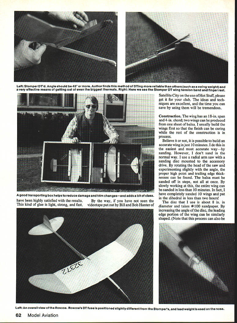
If you have not seen the videotape by Bill and Bob Hunter of Satellite City on the use of Hot Stuff, it is worth getting for your club — the techniques save a lot of time.
Construction (Stomper)
Wing
- Span: 18 in.; chord: 4 in. Two wings can be produced from one sheet of balsa.
- I build the wings first so the finish can cure while the rest of the model is constructed.
- Method: shape the wing by sanding on a radial-arm saw with an 8-in. sanding disc (#100 paper) mounted on the rotating head. By slightly angling and rotating the head you can find the proper high point and remove trailing-edge thickness in steps. This method can produce an accurate wing in about 10 minutes; I have sanded 10 wings and put dihedral in less than two hours.
- Increase the disc angle to shape the leading edge. After shaping, round the leading edge and smooth the wing with #220 paper.
- Dihedral: cut dihedral angles on the radial-arm saw by setting the head at half the required dihedral and using a plywood blade. Glue the joint with thick CyA, lightly sand, and finish.
- Finish: I have used dope, lacquer, MonoKote, and epoxy. Hobbypoxy has proven best for light weight, strength, and resistance to cracking. Apply Day-Glo orange to the tips for visibility.
- After two coats of epoxy have cured, glue turbulators in place with thick CyA.
- Mark name and AMA numbers with a Magic Marker.
Stab and Rudder
- No special tricks: round the leading edge and taper the last 3/8 in. at the trailing edges to allow bending for trim.
- Apply one coat of epoxy and set aside.
- If taped hinges are used, keep hinge gaps small and ensure free movement.
- Control throws should be minimal — just enough for trimming.
Fuselage
- Select a straight A-grained piece of balsa for the fuselage (not spruce — spruce tends to flex and make launches inconsistent).
- Glue a 3/16 x 3/4-in. spruce or pine support strip into the fuselage sides at the wing area.
- Accurately cut the small support piece and the fuselage cutout. Glue them together with the wing in place, then remove the wing and sand the cutout. Mark wing, stab, and rudder locations.
- Carve and sand fuselage to shape, taking care around the stab, rudder, and wing mounting.
- Use a short music-wire pin or 1/32-in. wire for the wing hold-down; ensure the wing seats squarely and firmly.
- Strengthen the nose with a hard-balsa or plywood nose block and add glass or epoxy fillets. A small ply doubler in the nose helps absorb tow or hard-launch shock.
- Cut and install the aluminum snuffer tube for the DT fuse; leave a flange on the tube to protect the fuselage from smoldering fuse. Five-minute epoxy can be used if you prefer it to thick CyA.
- Make the wing mounts as shown on the plans and sand the fuselage so the wing pivots freely for the pop-up DT.
- Mount stabilizer and rudder. Set the rudder as straight as possible. The stabilizer should have a slight left tilt (left side high when viewed from the rear), about 1/16 in.
- Give the fuselage a coat of epoxy. When cured, mount the wing pivot point and all hooks. Fit the wing assembly, insert pivot screws, and test the DT action to ensure the wing pivots freely and reliably.
Flying (Stomper)
- Make initial flights from an area with tall grass.
- Test-glide looking for a slight left circle. If it doesn't glide left, check for a crooked rudder.
- Trim slightly tail-heavy and launch slightly to the right of the wind with the nose high; use medium power.
- If it loops or turns hard to the right, the stab may have too much negative incidence (up-elevator).
- If the model "goes over the top" on launch, use rudder and stab adjustments plus wing twist (wash-in or wash-out) to control the glide.
- Stronger-launch arms often need more down-elevator; weaker arms may benefit from some up-elevator which helps roll recovery into the glide.
- Always use a DT fuse — many gliders have been lost by assuming "there's no lift today." Light the DT fuse every time.
- Select good lift and fly to win.
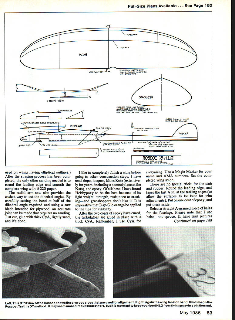
Roscoe 18 — Ross Jahnke
This design grew out of collaboration on the pop-up wing DT concept and my desire to fly my own design. Early flying used Blanchard's Polly; I liked the size but not the appearance, so I developed the Roscoe 18, which I find comfortable to build and fly.
Rather than a step-by-step building guide (the plans document construction), here are design reasons and construction highlights.
Fuselage
- The fuselage is streamlined for efficiency: DT fuse recessed, small hinge, and a short nose to minimize frontal area.
- Nose reinforcement: fiberglass was built into the nose. G-10 printed-circuit-board material is strong, rigid, easy to sand, and bonds with epoxy or CyA.
- Strength strip: a laminated 1/16 x 1/4-in. spruce strip was added to the bottom of the fuselage. This was chosen because:
- Hardwood fuselages are heavy.
- Spruce fuselages tend to be too flexible and can flutter during launch, making launches inconsistent.
- The balsa fuselage plus the laminated strip provides necessary rigidity and landing strength.
- Use epoxy fillets around the wing, fin, and front of the snuffer tube.
- Paint: two coats of Hobbypoxy (do not paint the fuselage section under the wing mount to keep DT movement smooth).
Wing
- Conventional construction, but wood selection is critical because the wing dictates final model weight.
- Center wing panels are joined with little dihedral because most lift is generated in the center section; most dihedral is in the tip panels. This preserves lift and maintains stability even in windy conditions.
- Leading-edge turbulator: added to minimize drag during the transition from power launch to glide. Studies at low Reynolds numbers indicate induced drag can increase dramatically at medium-range velocities; turbulators near the leading edge can reduce this drag. While simple HL airfoils were not specifically tested, the concept appears beneficial.
Tail
- Use light wood; a lighter tail reduces the amount of lead required to balance the model.
- For weight reasons, apply only one coat of Hobbypoxy to tail surfaces.
Flight and Trim Notes
- The model should fly right off the pad when built according to the plans. The main adjustment is center of gravity (CG) for a smooth glide.
- Warps in wing and tail have the most effect under power; CG location and stabilizer tilt matter more in the glide. Rudder adjustments are particularly sensitive during launch.
- With recommended stab tilt and wing setup, the model should have a good glide circle and require little rudder adjustment.
- Some models benefit from a bit of wash-in in the left wing for both power and glide phases.
- A small negative stabilizer incidence can aid recovery from bad launches but will reduce peak altitude; avoid negative stab unless necessary.
Optional DT
- If the complete pop-up DT is undesirable, the model can be built without it. A friend learned on a Roscoe with a swinging-weight DT and is still flying the same model after a year.
Contact
- Questions or comments may be sent to: Ross Jahnke, W65 N727 St. John Ave., Cedarburg, WI 53012.
When responding to advertisers, mention that you read about them in Model Aviation.
Transcribed from original scans by AI. Minor OCR errors may remain.

