
Typhoon
Editor's Note: Most scale-like profiles are designed for maximum aerobatic ability, the designers adding wing area by altering the planform, and changing the airfoil to a stunt type—usually with a significant increase in thickness. Intended to look more like the real aircraft, this design takes fewer liberties and, therefore, is not comparable to so-called scale profile stunt jobs in maneuverability. Nor is the wing unsightly because of exaggerated thickness. If the bulky looking profile suggests bigger engines, say up to .29s, be aware of the relatively low drag and modest wing area. It flies well with a .15 and probably would be quite fast with a .19.
THE TYPHOON was originally conceived as a replacement for the Hurricane fighter. Its initial planning was started in peace time but the start of World War II forced the building and testing program into an accelerated pace, causing many development problems. The first test pilots were very critical of the plane due to underpowered engines, structural failures and ground engine fires.
The Typhoon was designed first to combat heavily armored, well-armed, long-range fighters that Germany was reported to be building. Very early in its use, however, it was found to have no match under 10,000 ft. but at 20,000 ft. it was very vulnerable to enemy fighters. The thick wing and heavy wing loading that restricted its use at higher altitudes were necessary qualities for low altitude work. Its brute strength and heavy load carrying abilities made for a very stable aiming platform for all the armaments it carried.
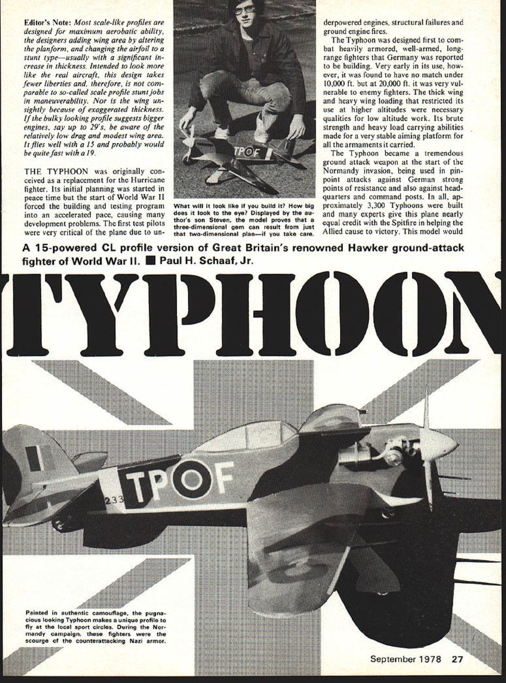
The Typhoon became a tremendous ground attack weapon at the start of the Normandy invasion, being used in pin-point attacks against German strong points of resistance and also against headquarters and command posts. In all, approximately 3,300 Typhoons were built and many experts give this plane nearly equal credit with the Spitfire in helping the Allied cause to victory. This model would be a .15-powered CL profile version of Great Britain's renowned Hawker ground-attack fighter of World War II.
Paul H. Schaaf, Jr. be a splendid addition to your collection of models. It is as tough as it looks.
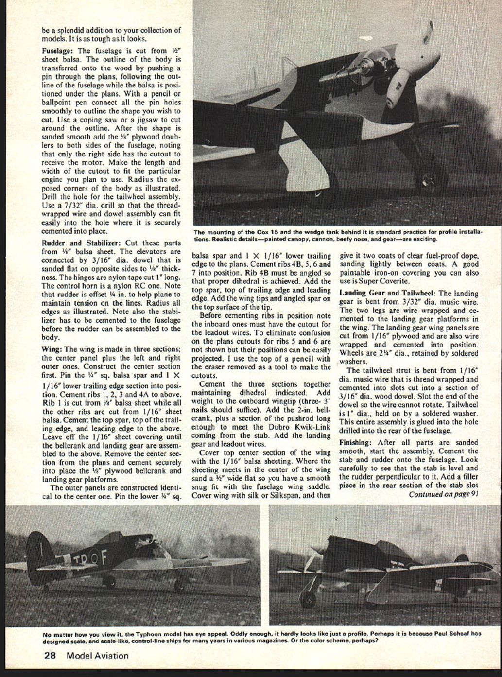
Fuselage: The fuselage is cut from 1/2" sheet balsa. The outline of the body is transferred onto the wood by pushing a pin through the plans, following the outline of the fuselage while the balsa is positioned under the plans. With a pencil or ballpoint pen connect all the pin holes smoothly to outline the shape you wish to cut. Use a coping saw or a jigsaw to cut around the outline. After the shape is sanded smooth add the 1/8" plywood doublers to both sides of the fuselage, noting that only the right side has the cutout to receive the motor. Make the length and width of the cutout to fit the particular engine you plan to use. Radius the exposed corners of the body as illustrated. Drill the hole for the tailwheel assembly. Use a 7/32" dia. drill so that the thread-wrapped wire and dowel assembly can fit easily into the hole where it is securely cemented into place.
Rudder and Stabilizer: Cut these parts from 1/8" balsa sheet. The elevators are connected by 3/16" dia. dowel that is sanded flat on opposite sides to 1/8" thickness. The hinges are nylon tape cut 1" long. The control horn is a nylon RC one. Note that rudder is offset 1/4" in. to help plane to maintain tension on the lines. Radius all edges as illustrated. Note also the stabilizer has to be cemented to the fuselage before the rudder can be assembled to the body.
Wing: The wing is made in three sections; the center panel plus the left and right outer ones. Construct the center section first. Pin the 1/4" sq. balsa spar and 1 x 1/16" lower trailing edge section into position. Cement ribs 1, 2, 3 and 4A into position above. Rib 1 is cut from 1/8" balsa sheet while all the other ribs are cut from 1/16" sheet balsa. Cement the top spar, top of the trailing edge and leading edge to the above. Leave off the 1/16" sheet covering until the bellcrank and landing gear are assembled to the above. Remove the center section from the plans and cement securely into place the 1/8" plywood bellcrank and landing gear platforms.
The outer panels are constructed identical to the center one. Pin the lower 1/4" sq. balsa spar and 1 x 1/16" lower trailing edge to the plans. Cement ribs 4B, 5, 6 and 7 into position. Rib 4B must be angled so that proper dihedral is achieved. Add the top spar, top trailing edge and leading edge. Add the wing tips and angled spar on the top surface of the tip.
Before cementing ribs in position note the inboard ones must have the cutout for the leadout wires. To eliminate confusion on the plans cutouts for ribs 5 and 6 are not shown but their positions can be easily projected. I use the top of a pencil with the eraser removed as a tool to make the cutouts.
Cement the three sections together maintaining dihedral indicated. Add weight to the outboard wingtip (three — 3 nails should suffice). Add the 2-in. bellcrank, plus a section of the pushrod long enough to meet the Dubro Kwik-Link coming from the stab. Add the landing gear and leadout wires.
Cover top center section of the wing with the 1/16" balsa sheeting. Where the sheeting meets in the center of the wing sand a 1/4" wide flat so you have a smooth snug fit with the fuselage wing saddle. Cover wing with silk or Silkspan, and then give it two coats of clear fuel-proof dope, sanding lightly between coats. A good paintable iron-on covering you can also use is Super Coverite.
Landing Gear and Tailwheel: The landing gear is bent from 3/32" dia. music wire. The two legs are wire wrapped and cemented to the landing gear platforms in the wing. The landing gear wing panels are cut from 1/16" plywood and are also wire wrapped and cemented into position. Wheels are 2 1/4" dia., retained by soldered washers.
The tailwheel strut is bent from 1/16" dia. music wire that is thread wrapped and cemented into slots cut into a section of 3/16" dia. wood dowel. Slot the end of the dowel so the wire cannot rotate. Tailwheel is 1" dia., held on by a soldered washer. This entire assembly is glued into the hole drilled into the rear of the fuselage.
Finishing: After all parts are sanded smooth, start the assembly. Cement the stab and rudder onto the fuselage. Look carefully to see that the stab is level and the rudder perpendicular to it. Add a filler piece in the rear section of the stab slot where the open groove occurs. Move the elevators to check for any binding of the connector dowel in passing through the fuselage. Cement the wing into position ensuring it is perpendicular to the fuselage.
The exhaust stacks on the inboard side of the body are cut from 1/4" balsa sheet cemented to a strip of 1/32" plywood or thin cardboard. Make the cannon from 3/16" balsa sheet. Both of the above are painted black and assembled to the model after it has been painted. Give the plane two coats of clear fuel-proof dope, sanding with #300 paper between the coats. Using a soldered coupling, join the pushrod from the wing to the Kwik-Link. With the bellcrank parallel with the fuselage, the elevators should be level.
My plane was painted as follows. Fuselage top and sides, top of wing and stab, rudder, a splintered pattern of brown and green. The underside of the fuselage, wing, stab, and panels on the landing gear a light blue. The canopy is silver with the canopy frame brown-painted tape. The spinner is gray. The roundels, lettering, numbers and other markings are cut from Monokote Trim Sheets. Outboard of the cannon, I added a 1/8" wide strip of yellow equally above and below the point of the leading edge.
The plane is powered by a .15 motor (mine uses a Cox .15). Prop is a 9 x 3 or an 8 x 4 nylon one. The gas tank is mounted very easily by using two screweyes (opened up) and rubberbands, centered behind the engine. Check the C.G., adding weight as required. My plane is flown on 52' lines, .015" dia.
Flying: For your first flights use the outer hole in the control horn, since the plane's reactions will be milder than if the inner ones are used. Since the frontal area on a profile plane is small, the model really moves out under power.
After you start the engine and it is running to your satisfaction, move out to the center of the circle and double check the controls. When all is ready, give your partner the signal to release the plane. As it speeds along the ground slowly feed in a small amount of up, and as it takes off and reaches about 10 feet of altitude, level off. Move the handle gently and get the feel of the plane before you start more violent maneuvers. As you know, every model has different characteristics and rates of response. Know your model first before experimenting. When the motor stops, gradually feed in up as you get close to the ground for a perfect three-point landing.
I'm sure you will be thrilled to have and fly this historic and powerful-looking model. Fully decorated it looks great.
Transcribed from original scans by AI. Minor OCR errors may remain.

