
Undertaker
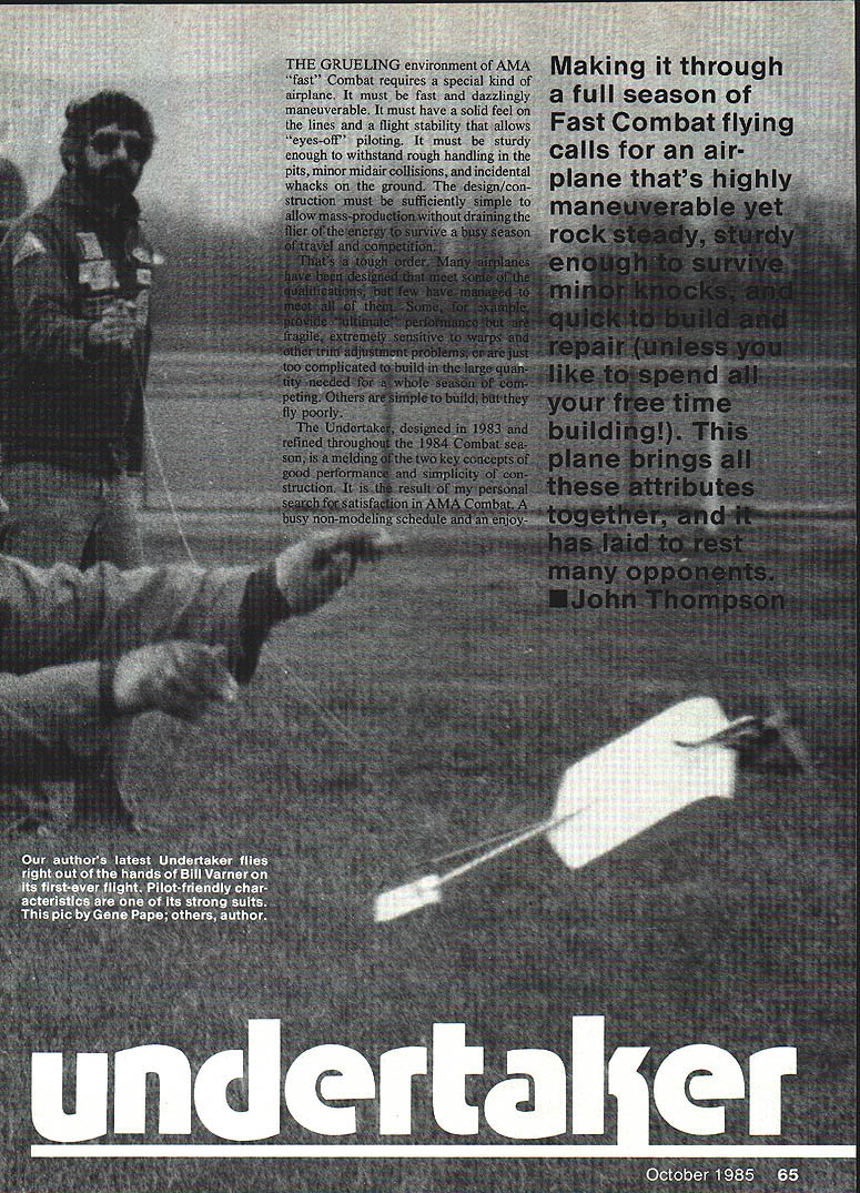
The grueling environment of AMA "fast" Combat requires a special kind of airplane. It must be fast and dazzlingly maneuverable. It must have a solid feel on the lines and a flight stability that allows "eyes-off" piloting. It must be sturdy enough to withstand rough handling in the pits, minor midair collisions, and incidental whacks on the ground. The design and construction must be sufficiently simple to allow mass production without draining the flier of the energy to survive a busy season of travel and competition.
Many airplanes meet some of these qualifications, but few meet all of them. Some provide ultimate performance but are fragile, extremely sensitive to warps and other trim problems, or are too complicated to build in the large quantities needed for a season. Others are simple to build but fly poorly.
The Undertaker, designed in 1983 and refined through the 1984 Combat season, is a melding of two key concepts: good performance and simplicity of construction. It resulted from a personal search for a Combat design that would be quick to build, predictable to fly, and easy to repair — qualities important to a flier with limited building time.
Like many beginners, I experimented with all-balsa designs and then foam wings, attracted by the performance of high-aspect-ratio "foamies." My early tapered-wing foam designs, however, proved too susceptible to line-tension problems and unpredictable when slightly out of trim.
My first successful design was the Ax, a balsa airplane with a foam leading edge. The foam leading edge was essential for snagging the streamer leader for the wing kill. The Ax used a rectangular wing planform and a fairly thick airfoil, copied from an early design by Phil Granderson, with construction influenced by Gene Pape and Norm McFadden. Once sorted, the 42-in. span Ax was predictable in all flight attitudes, launched and flew immediately regardless of wind, turned well, flew acceptably when warped or poorly trimmed, withstood minor damage, and was quick to build.
The Ax's serious flaw was fragility: in trying to simplify and lighten it, I ended up with a plane that would explode on contact with another airplane or the ground. I returned to the drawing board wanting the Ax's flight characteristics and simplicity but with greater strength and parts that could be recycled after crashes.
I again considered foam wings for strength and drew on the ultra-simple concept of Gene Pape's Dogfighter, a popular beginner, quick-build Combat plane. The Undertaker blends these ideas: foam strength and wing-kill capability, a tapered wing planform with a moderately high aspect ratio for good turning, the airfoil moments and predictable response of the Ax, and the Dogfighter's construction simplicity. The first prototype was satisfactory from the start.
I later made a larger version for the 1984 Reno Nats. I am pleased with both the original 45-in. span version and the Reno 47-in. span version; the only construction difference is to add an inch to each wing core for the larger model. Properly built, the Undertaker is stable in level flight, quick and tight-turning, pulls well on the lines for a good feel at the handle, and is easy to control upwind or downwind. It avoids many bad habits of thin, high-aspect-ratio designs (line-tension sensitivity, bobbing, wobbling, warp-sensitive control loss).
The design is strong enough to survive most minor crashes and collisions and is frequently repairable even after serious damage. When not repairable, the fuselage/tail assembly and controls are usually reusable unless center-punched. Replacement wing cores are easy to install because the spar channel is not hidden under the engine mount. A new wing core can often make the airplane like new in a couple of hours.
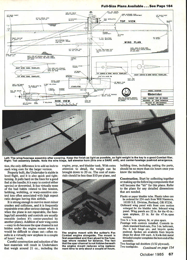
Careful construction and material selection typically yield Undertakers weighing about 21 oz., including engine, prop, and bladder tank; with extra care this can be brought down to 20 oz. Material cost should be under $10 per plane, and build time (including cutting parts) can be six hours or less once you know the technique.
Construction
Start by collecting or making the following components to form a kit. Refer to the plans for detailed dimensions.
- Plastic or paper bladder tube (plastic tubes can be ordered).
- Wing panels: outboard wing panel (with front core section enlarged for the bladder tube) and inboard wing panel. Wing panels are 22 in. each for the 45-in. span airplane, 23 in. each for the 47-in. span version.
- Two spars, 3/4 x 4 in., of spruce, fir, or pine.
- Fuselage with controls installed. Controls include standard lead-outs, Fox 3-in. bellcrank, No. 6 bolt hinge pin, and bicycle spoke pushrod. Use a Kwik-link metal threaded coupler at the horn end of the pushrod assembly.
- Two fuselage tail doublers (3/32 in. plywood).
- Two toothpicks (for alignment guides).
- Two engine mount beams, 3/8 x 3/4 in., maple.
- Nacelle, 3/4-in. plywood (engine mounting plate).
- Inboard wing tip with eyelets installed.
- Outboard wing tip.
- Lead wing-tip weight, 1/4 oz.
- Stabilator: 1/4 x 3 x 36-in. Sig tapered balsa stock.
- 6-in. hinge pin of 3/32-in. music wire.
- Two 1/4-in. O.D. brass hinge pin stops.
- Hinge bushing: 1/8-in. O.D. brass.
- Large elevator horn (Kraft RC tail horns recommended, or steel fine-adjustment Combat horns from Dark Ages Racing Equipment). Do not use standard-size control horns — they are too small.
- Blind nuts for engine attachment (No. 6 blind nuts and bolts recommended).
Sequence (construction steps)
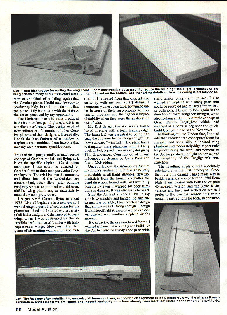
- Cut the wing panels with a hot-wire cutter using the templates shown on the plans.
- Use rectangular templates to core out the cavities. Enlarge the front outboard cavity and install the bladder tube. Use a 1/4-in. drill bit or sandpaper wrapped around a 1/4-in. dowel to enlarge the hole. If using a jig, drill it and guide the core to prevent the hole from wandering. Save the foam piece you cut out to use later as an assembly jig.
- Saw the fuselage, tail, tail doublers, tips, and engine mount beams from the specified materials. Mark centerlines on both sides of the fuselage and locate the toothpick guide holes. Groove the fuselage for the bellcrank posts.
- Assemble the control system: mount a Fox bellcrank on a No. 6 bolt, using nuts top and bottom to hold it. Bush the lead-outs with grommets or brass tubing and put the bicycle spoke keeper dowel in the inner bellcrank arm hole. A long piece of brass tubing cut jagged at one end makes a good bit for drilling the long pushrod exit hole through the fuselage. Some minor adjustments or a slight bend in the rod may be needed for clearance. With practice you should be able to drill the hole so the system operates freely.
- Attach the fuselage and doublers with cyanoacrylate (CYA). Sand, drill, and install the brass tube bushing. Ensure the hole is straight; use a drill press if possible.
- Install toothpicks in the fuselage holes to serve as wing-alignment guides. Attach the wing cores with 5-minute epoxy. Use bearing-tip blanks cut from the wing as a jig to hold the assembly straight while gluing. Align panels using the fuselage centerlines. The back of the wing spar notch should line up with the front of the fuselage cutout so the spar lays across and butts the back of the cutout.
- Glue in the spars with a white glue (Pica Products Glue-It recommended; it sands easily). Hold spars in place while the glue dries by reassembling the cores, spars, and glue on the blanks (lined with wax paper), weighting the sandwich until dry.
- Attach the wing tip weight to the outboard part and install both tips, threading the lead-outs through the inboard tip eyelets. The templates slot the back of the panel to allow lead-outs to travel through their proper channels. Do not tamper with the line rake — it is key to good line tension.
- Strengthen the wing center and prevent flexing: run a strip of 3/8-in. strapping tape diagonally from the front root to the back tip on the inboard side, top and bottom. Add a short piece spanwise across the fuselage center, top and bottom, as far back as it can lie flat; this significantly strengthens the center section and helps avoid damage in minor crashes.
- Put your AMA numbers on the plane as required by the AMA Safety Code. Cover the cores with FasCal using a low-heat setting.
- Attach the tail using the music wire hinge pin. Glue the brass hinge pin stoppers to the hinge pin with CYA to prevent sideways sliding. CYA-glue the hinge pin to the elevator (a little baking soda helps secure the bond), sand the joint, and wrap the pin area with FasCal scraps. Cover the whole tail with FasCal (a single piece can be wrapped around).
- Install the elevator horn. If using a Kraft horn, place a 1/32-in. plywood plate underneath to prevent lifting under stress. DARE horns do not require the plate. Finish the tail boom with FasCal or other plastic covering.
- Connect the pushrod to the elevator horn with a Kwik-link. Start with minimal movement needed: set the horn near the top of the Kraft horn or about five holes down on the DARE horn.
- Glue the maple engine bearers to the plywood nacelle and cut out the center to fit the assembly to the fuselage. The rear of the beams should butt up against the spar. Shape and taper the engine mount beams front and rear as needed.
- Rubber-band the engine (mounted with prop and bolts) onto the engine mount. Plug the mount onto the plane and move the engine forward or backward until the plane balances at about 25% of the wing chord (roughly on the spars). Mark the engine mounting hole locations and drill for blind nuts.
- Attach the engine mount with slow-cure epoxy and fill gaps later with 5-minute epoxy. Finish the mount and exposed parts of the fuselage with 5-minute epoxy.
- Drill access and drain holes in the bladder tube and fuel-proof the hole edges. Securely tie the lead-out ends.
Flying
Your Undertaker should be under control right out of the launch. Some Kwik-link and horn adjustment may be needed to equalize turns and find proper turn radius.
- Resist the temptation to use excessive elevator travel. Too much elevator induces a stall and makes the plane vulnerable to an easy kill by an opponent. If a large amount of travel seems necessary to get the plane to turn, the model is nose-heavy; this can be corrected within limits by adding tail weight.
- If the plane is "nervous" and won't fly level, it is tail-heavy and elevator travel must be minimized.
Once your Undertaker is trimmed and flying well, the remaining factors between you and success in Combat are practice and lots of Combat flying.
Transcribed from original scans by AI. Minor OCR errors may remain.

