
Updating the Old Airtronics: Frequency Scanner
Eloy Marez
This article describes simple mechanical modifications to adapt the Airtronics RC Frequency Scanner (originally covering 72–75 MHz) to the new channels and to make crystal changes easier and faster for contest use.
Overview of the unit
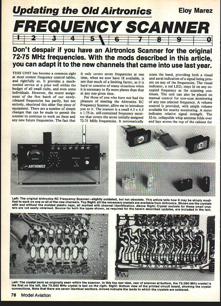
The Airtronics scanner is a compact (4.5 × 4.5 × 1.75 in) self-contained frequency monitor that scans seven frequencies (originally the assigned 72–75 MHz channels). Features include:
- Automatic band scanning with visual (red LED) and aural indication of signals; LED stays lit on an occupied frequency as scanning continues.
- Manual selection for non-scan monitoring of any one frequency.
- Volume control and a meter for relative signal strength.
- 32-inch collapsible whip antenna that folds across the top for storage.
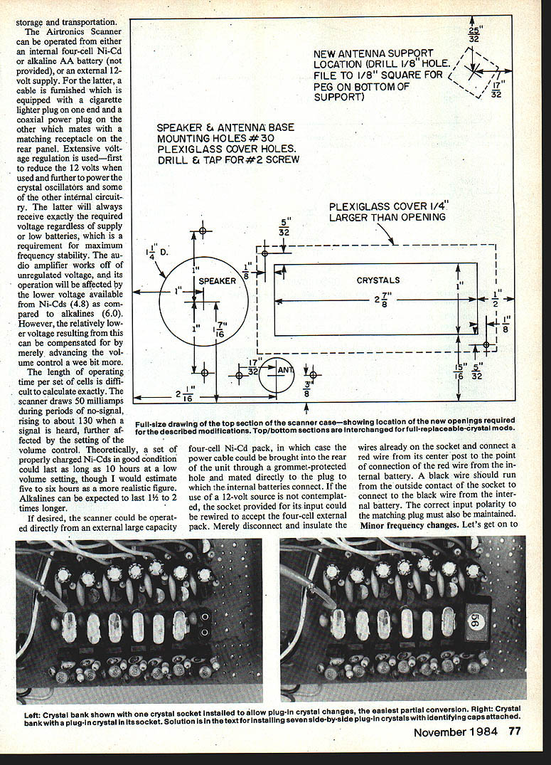
- Operation from an internal four-cell Ni-Cd or alkaline AA pack, or from an external 12 V supply (cable with cigarette-lighter plug to coaxial power plug furnished).
- Extensive voltage regulation for the crystal oscillators and other internal circuitry for frequency stability; audio amplifier runs from unregulated voltage.
Power consumption and operating time:
- Quiescent draw: ~50 mA; with signal: ~130 mA (affected by volume setting).
- Properly charged Ni-Cd cells: theoretically up to 10 hours at low volume, realistically 5–6 hours.
- Alkalines: expected to last 1–2 times longer.
- The unit can be run from an external large-capacity 12 V source if preferred.
Minor frequency changes
No circuit changes are required to cover the 72–75 MHz band; changes are mostly mechanical (crystal swaps).
Simple swap (one or two frequencies)
- Remove top and bottom halves (four sheet-metal screws per side). The rear cover may be removed later as needed.
- Decide which original frequency(s) to replace. For reference, think of the seven frequencies as positions 1–7 left-to-right when viewing the front LEDs (72.080 = No. 1 on the left; 75.640 = No. 7 on the right). Note: on the PC board the crystal order is inverted relative to the front panel (crystal positions read right-to-left).
- Remove the unwanted crystal(s):
- Use a small soldering iron (≈12 W). Do not use a soldering gun.
- Use desoldering wick to remove solder quickly. Avoid prolonged high heat to protect crystals.
- Install new crystal(s):
- You may solder new crystals in place, or install sockets for faster field replacement.
- If soldering, clean solder off crystal pins for reuse in sockets if desired.
Crystals: types and ordering
- Use receiver crystals (order as receiver crystals).
- The scanner uses fundamental-frequency crystals; overtone crystals may not work. If unsure, order crystals from Airtronics (they stock new and old frequencies, typical price cited $7.50).
- Likely HC-25/U type crystals are required. Do not accept HC-18/U (same body size but long wires rather than pins) unless you intend to solder them in.
- Airtronics crystals come with molded plastic caps identified by color and channel number; caps may be too wide to fit seven side-by-side without trimming.
Crystal sockets
Two socket types exist:
- Board-mounted (same pin diameter and spacing as the crystals) — Kraft Part No. 120-074 (board-mounted type) — use this if mounting sockets directly into the PC board. (Price example: $3.00 each.)
- Flat-pin type (wider pins and spacing) — Kraft Part No. 120-141K — used for the support-mounted socket board described below. (Price example: $1.00 each.)
Note: small crystal sockets are not commonly found at general hobby stores; Kraft Systems or specialized suppliers carry them.
Full-house update (support-mounted socket board + clear window)
If you want quick field changes without removing the top cover each time (recommended for contest use), install a support-mounted crystal socket board and a clear plastic window so crystals are visible and accessible.
Parts and materials
- Prototype perforated board, 0.1 in hole spacing (epoxy preferred; phenolic acceptable).
- Kraft socket type 120-141K (flat-pin) — one per crystal position.
- 7/16 in spacers and 4-40 screws (for mounting the socket board over the scanner board).
- No. 22 or 24 uninsulated solid wire, about 1-1/2 in lengths for wiring inline.
- Cyanoacrylate (very small drop to secure sockets to the board).
- Nylon spacer or fiber washer to insulate screw head side.
- 1/16 in Plexiglas for the clear top (optional).
- Tools: small soldering iron, desoldering wick, small drill, tweezers, Dremel or fine saw/files for sheet metal, small brush and alcohol for cleaning.
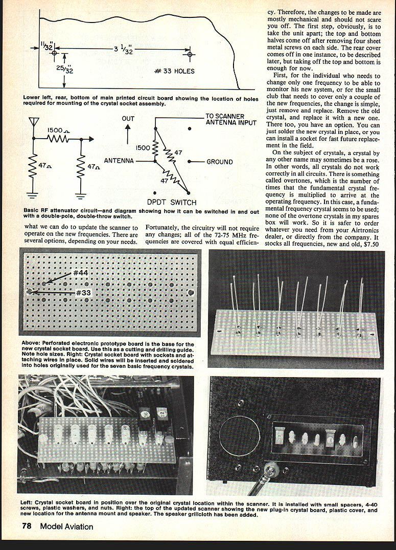
Making the socket board (summary)
- Cut perf board to 14 × 32 holes (0.1 in grid).
- Drill new holes as indicated (photo reference in original article). The 14 crystal positions are arranged in two rows of seven on 0.300 in centers.
- Install Kraft 120-141K sockets in the perf board using a tiny drop of cyanoacrylate (avoid wicking glue into the socket).
- Fold the flat pins inward to secure and solder a 1.5 in length of uninsulated No. 22 or 24 solid wire to each socket pin.
- Desolder and remove all seven crystals from the scanner PC board and clean solder off their pins. Apply paste flux, heat, and wipe solder clean.
- Drill two mounting holes in the scanner PC board adjacent to the original crystal area (one hole will cut through an unused land; the other will cut into a land that has a charge diode and red wire). Perform a small modification:
- Remove the diode completely from the board.
- Install a short lead on the opposite end of the diode down onto the board land where its bent-over lead was soldered. Resolder and clip excess.
- Reattach the red wire to the top diode lead so original connections are preserved. This creates clearance for spacers.
- Mate the socket board to the scanner board:
- Insert a crystal into each socket and feed its pair of wires through corresponding holes in the scanner board.
- Install 7/16 in spacers and 4-40 bolts; use a nylon spacer or fiber washer under screw heads to insulate the land side.
- Ensure wires are not buckling or shorting; trim and solder wires to the board lands and clip excess.
- If tall components (e.g., capacitors) interfere, heat their solder joints and push them down to clear the socket board.
- Clean flux residue with alcohol and a stiff brush.
Reassembly and labeling
- Reconnect the speaker and battery and check normal scanner operation before final assembly.
- Note LED vs. crystal orientation: front-panel LEDs read left-to-right in ascending frequency, but crystal positions are right-to-left. Relabel front panel positions simply as 1–7 to maintain the relationship between installed crystals and LEDs.
- Remount speaker, antenna support and antenna after completing the top cover modifications (see next section).
Top cover modifications and remounting
To provide access and visibility for the plug-in crystals:
- Remove all hardware from the top cover.
- Swap top and bottom covers (the original top holes are not suitable for new openings).
- Cut new openings in the cover:
- The covers are steel; use a fine-tooth Dremel blade and finish with files.
- If available, use Greenlee chassis punches for clean round and rectangular holes (1-1/4 in round for speaker; 1 in square used with ends for rectangle).
- Install a grille cloth over the speaker hole; secure with adhesive.
- Remount the antenna and antenna support. The support will need a small square hole at its new location; reattach with silicone rubber.
- Optional: mount a clear 1/16 in Plexiglas top attached with No. 2 machine screws (one screw can be removed for quick pivot access during contests).
- Reconnect antenna and speaker wires and button up the unit.
Signal attenuator (subheading)
Strong nearby signals at a flight line can swamp the scanner. Add a switchable attenuator to reduce sensitivity when needed.
Attenuator parts and placement
- Three resistors (values depend on desired attenuation — schematic referenced in original article).
- One DPDT switch installed on the rear cover.
- Switch used in the article: C&K DPDT Model No. 1201 (small, high-quality). Any small DPDT slide or toggle switch that fits may be used.
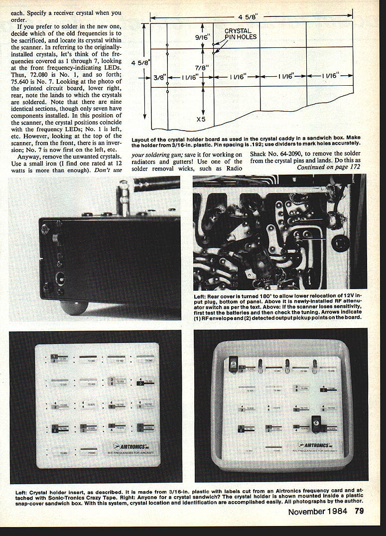
- Rear cover is rotated 180 degrees when remounted and the 12 V input socket moved toward the bottom; install the attenuator switch above it.
Operation
- Switch set to “High” leaves attenuator out of circuit (maximum sensitivity).
- Switch set to “Low” inserts the attenuator (about 30 dB attenuation).
- Use attenuator and collapse the antenna when monitoring strong nearby signals; switch out and extend antenna periodically to check for weaker incoming interference.
Crystal holder (Deluxe RC Crystal Caddy)
A simple storage/transport/identification solution for crystals.
Materials and construction:
- Use a plastic sandwich box with snap-on cover; recommended example: "Superseal" #3427 (inside dimension 5.5 in square).
- Make an insert (crystal holder) from plastic at least 1/8 in thick. Drill 36 holes with a #56 bit. Crystal pin spacing is .192 in — use dividers set to the correct spacing and mark holes with them for accuracy.
- Labels cut from an Airtronics Frequency Card (available from Airtronics). Use thin double-sided tape (e.g., Sonic-Tronics Crazy Tape) to attach labels.
- Secure the holder in the case with tape and attach a piece of foam rubber to the cover to hold crystals in place during transport.
Cars and boats
- The scanner also works on 75 MHz car and boat frequencies.
- Convert by swapping crystals using the same methods described. Airtronics stocks those crystals and labels (check the other side of the frequency card).
Tuning and maintenance
- If sensitivity seems degraded (after checking batteries), check tuning:
- Pick up the modulated waveform and detected output at test points on the PC board (see photos in original article).
- Tune in the middle of the band using a distant antenna as a signal source.
- Adjust the RF and IF transformers for maximum signal — physically located in line from the antenna input toward the center of the unit.
- Crystals and sockets: Airtronics has agreed to furnish sets of the new frequency crystals to duly registered purchasers (write Airtronics for current information).
Parts update and suppliers
- Two types of crystal sockets (for HC-25 types and similar) are cataloged by Seminole Electronic Supply, 2822 North 32nd St., Unit 1, Phoenix, AZ 85008. Check their catalog for availability and current pricing.
- Kraft socket part numbers referenced:
- 120-074 (board-mounted type)
- 120-141K (flat-pin type for the socket board)
End of article.
Transcribed from original scans by AI. Minor OCR errors may remain.

