
U.S. MALE
Clarence Haught
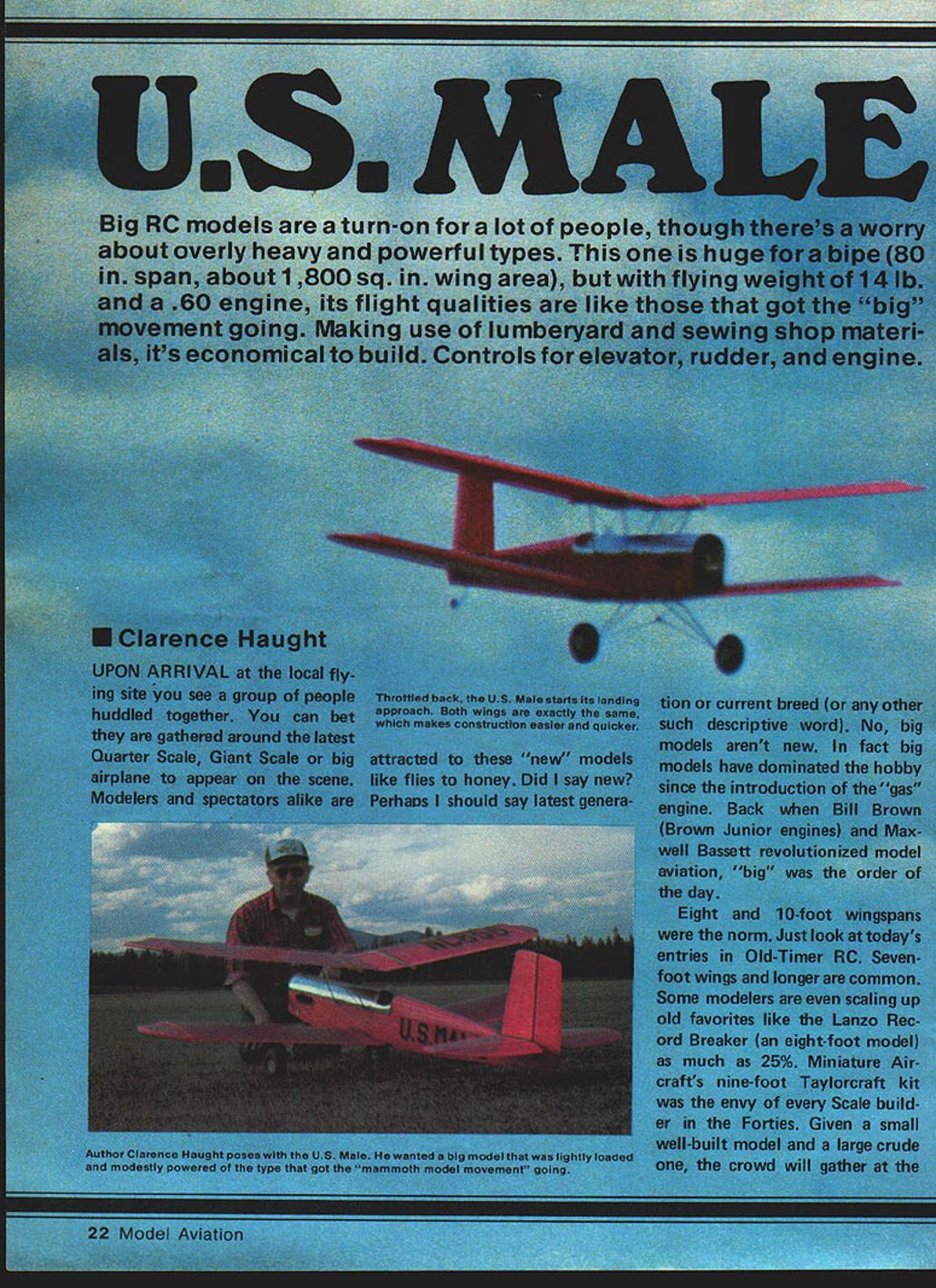
Big RC models are a turn-on for a lot of people, though there's a worry about overly heavy and powerful types. This one is huge for a biplane (80 in. span, about 1,800 sq. in. wing area), but with a flying weight of 14 lb. and a .60 engine, its flight qualities are like those that got the "big" movement going. Making use of lumberyard and sewing-shop materials, it's economical to build. Controls: elevator, rudder, and engine.
Upon arrival at the local flying site you see a group of people huddled together. You can bet they are gathered around the latest quarter-scale, giant-scale, or big airplane to appear on the scene. Modelers and spectators alike are attracted to these "new" models. No, big models aren't new. In fact, big models have dominated the hobby since the introduction of the "gas" engine. Back when Bill Brown (Brown Junior engines) and Maxwell Bassett revolutionized model aviation, "big" was the order of the day.
Eight- and ten-foot wingspans were the norm. Just look at today's entries in Old-Timer RC. Seven-foot wings and longer are common. Some modelers are even scaling up old favorites like the Lanzo Record Breaker (an eight-foot model) as much as 25%. Miniature Aircraft's nine-foot Taylorcraft kit was the envy of every scale builder in the Forties. Given a small well-built model and a large crude one, the crowd will gather at the larger model every time. Not that this makes it right. It's just our nature. We like big models, big cars, big buildings, big anything. Well, almost.
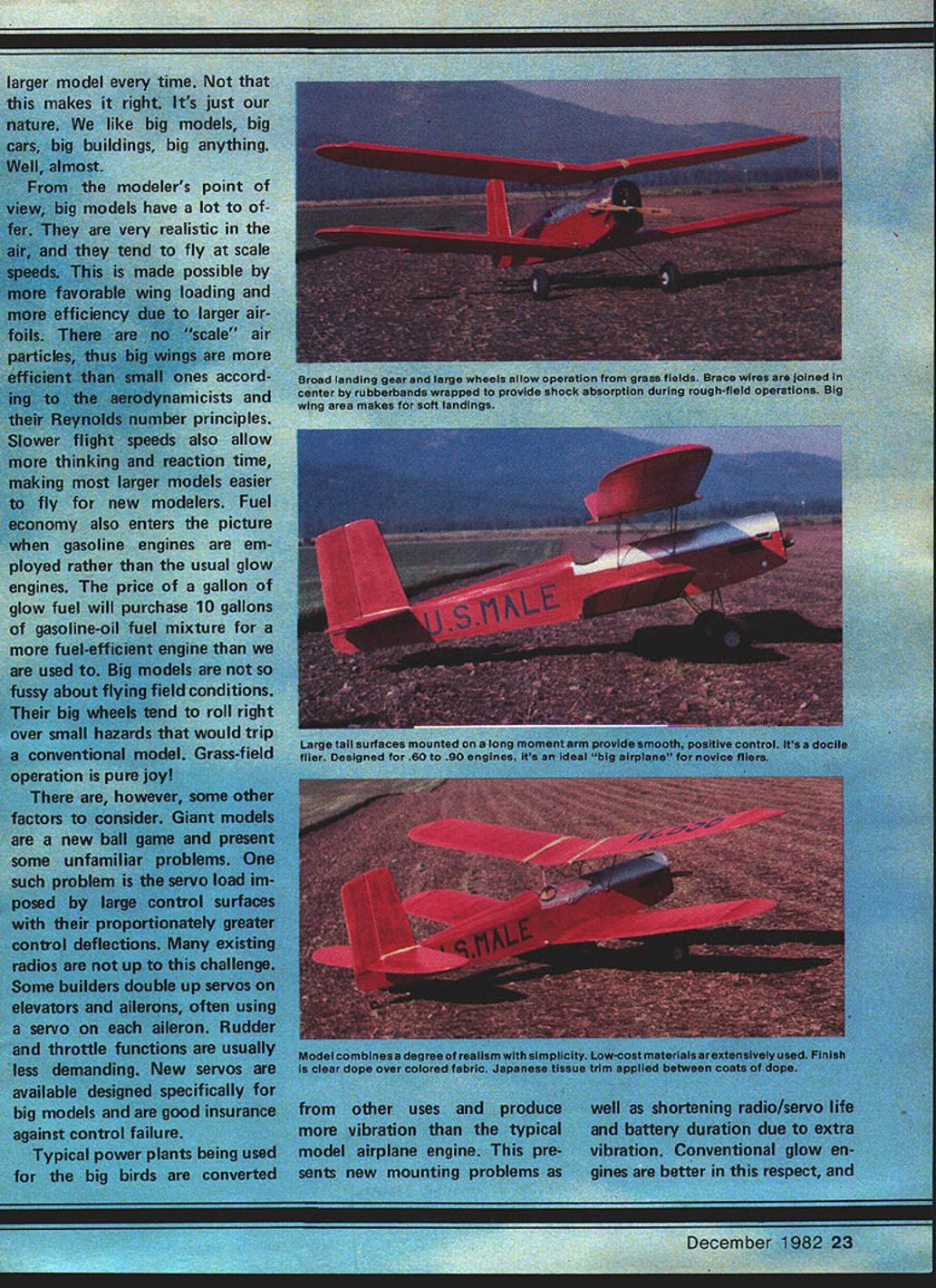
From the modeler's point of view, big models have a lot to offer. They are very realistic in the air and tend to fly at scale speeds. This is made possible by more favorable wing loading and greater efficiency due to larger airfoils. There are no "scale" air particles; big wings are more efficient than small ones according to aerodynamics and Reynolds-number principles. Slower flight speeds also allow more thinking and reaction time, making most larger models easier to fly for new modelers. Fuel economy also enters the picture when gasoline engines are employed rather than glow engines. The price of a gallon of glow fuel will purchase ten gallons of gasoline‑oil fuel mixture for a more fuel-efficient engine than we are used to. Big models are not so fussy about flying-field conditions. Their big wheels tend to roll right over small hazards that would trip a conventional model. Grass-field operation is pure joy!
There are, however, some other factors to consider. Giant models are a new ball game and present some unfamiliar problems. One such problem is the servo load imposed by large control surfaces with their proportionately greater control deflections. Many existing radios are not up to this challenge. Some builders double up servos on elevators and ailerons, often using a servo on each aileron. Rudder and throttle functions are usually less demanding. New servos designed specifically for big models are good insurance against control failure.
Typical powerplants being used for the big birds are converted from other uses and produce more vibration than the typical model airplane engine. This presents new mounting problems as well as shortening radio/servo life and battery duration due to extra vibration. Conventional glow engines are better in this respect, and prop-speed reduction-drive units and multiple-engine drive units have been developed for use in larger models. However, these systems do not offer the fuel-economy advantages of gasoline engines.
The designer of a conventional model can rely on time-honored rules of thumb to produce a model of sufficient strength and rigidity-flexibility to withstand anticipated air loads during projected maneuvers. Because of the increased size and the vibration factors of gasoline engines, the designer of the large model is faced with new problems to solve. The typical result is an overly strong (read: heavy) structure that is more than adequate for the job or, on the other side of the ledger, perhaps a structure with a built-in weakness which may be revealed at an inopportune moment.
This type of experimental engineering can lead to costly lessons in time and material, to say nothing of the potential for these models to cause damage. "The bigger they are, the harder they fall" has implications in this hobby, and this is further complicated by the speed factor. One could also say, "The faster they fly, the harder they impact."
The original concept of the quarter-scale or giant-model movement, as advocated by Bill Northrop, was to build big but to build light. He reasoned that real airplanes are built structurally light but strong, and they are not built to be crash-proof. Functional struts, wires, and braces can reduce the structural weight considerably. I interpreted his thoughts as suggesting models built somewhat like Old-Timer free flight with radio control. Some models have been designed around this criterion. Others have become scaled-up versions of typical RC models, resulting in high wing loadings and airspeed.
I wanted to get in on the fun like everyone else, but the thought of "starting over" with the purchase of a gasoline engine and a heavy-duty radio was distressful. I already had a considerable inventory of "standard" modeling gear. Thus, the thought of designing something that would be big but flyable on a standard .60 engine with my existing radio excited me. It also occurred to me that newcomers attracted to modeling by the large machines shouldn't have to start with a small trainer. Why not design a simple, docile big bird that could serve as a trainer while letting the neophyte in on all the fun? Remembering my own first powered RC model, an Old-Timer Powerhouse, and the ease with which it taught me the fundamentals of RC, clinched it. The final criteria: low cost. Much of the materials should come from the local lumberyard, the covering from the sewing shop, and the finish ordinary clear butyrate dope from the airport.
FULL-SIZE PLANS AVAILABLE. SEE PAGE 164.
Design and Specifications
- Type: Biplane (not scale; in the spirit of 1930s mail planes)
- Wingspan: 80 in. (each wing)
- Total wing area: ~1,800 sq. in.
- Finished weight (with ballast to achieve CG): 14 lb.
- Wing loading: ~1½ lb. per sq. ft. (compare to a typical 25-lb., 1,000 sq. in. model at over 3½ lb. per sq. ft.)
- Engine: .60 glow (designed to use existing standard equipment)
- Controls: three-channel (elevator, rudder, throttle) — generous dihedral for stability
A flat-bottom airfoil coupled with typical Old-Timer free-flight moments produces a model that basically will fly itself. It will recover unassisted from unusual attitudes by simply releasing the controls—given reasonable altitude. Three-channel control was chosen to simplify initial flight training. The U.S. Male is not a scale model but was designed to be docile and suitable as a trainer.
Materials and Cost-Saving Measures
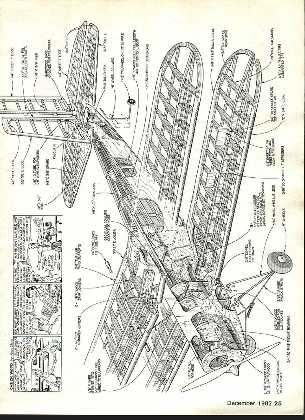
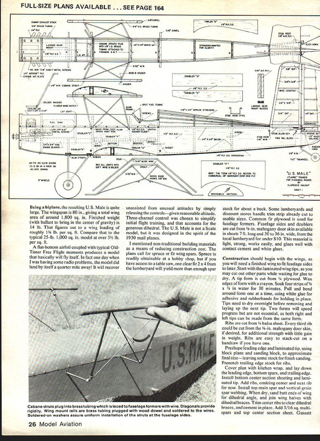
The plans call for spruce or fir wing spars. Spruce is readily obtainable at a hobby shop, but if you have access to a table saw, one clear fir 2 x 4 from the lumberyard will yield more than enough spar stock for about a buck. Some lumberyards and discount stores handle trim strip already cut to usable sizes. Common fir plywood is used for fuselage formers.
Fuselage sides and doublers are cut from 3/8-in. mahogany door skin available in sheets 7 ft. long and 30 to 36 in. wide, from the local lumberyard for under $10. This material is light, strong, works easily, and glues well with contact cement and white glues.
Construction
Wings
- Begin with the laminated wing tips. Cut a tip form from 1/8-in. plywood and wax the edges with a crayon. Soak four strips of 1/4 x 1/8 in. for 30 minutes. Pull and bend around the form one at a time, using white glue as the adhesive and rubber bands to hold in place. Tips need to dry overnight before removing and laying up the next tip. Two forms will speed progress but are not essential.
- Cut ribs from 1/8-in. sheet balsa. Every third rib may be cut from 3/32-in. mahogany door skin for additional strength with little gain in weight. Ribs are easy to stack-cut on a bandsaw if you have one.
- Preshape the leading edge and laminated tips using a block plane and sanding block to approximate final size—leave some stock for finish sanding. Pre-notch trailing-edge stock for the ribs.
- Cover the plan with kitchen wrap, and lay down the leading edge, bottom spars, and trailing edge. Install bottom center-section sheeting and the laminated tip.
- Add ribs, omitting the center and the adjacent rib for the tank/center-section cutout. Install the top main spar and vertical-grain spar webbing.
- When dry, sand butt ends of the wing for the dihedral angle, join wing halves with dihedral braces, and cement in place.
- Add 3/16-in. square multi-spars and top center-section sheet; gusset the trailing edge at the tips. Give the wing a final sanding and add wire reinforcement at the trailing-edge center.
- Both wings are identical.
Stabilizer, Elevator, Fin, and Rudder
- Structures are straightforward. Ribs are simply 3/8 x 3/8 balsa stock sanded to shape after assembly.
- Make your own elevator joiner from 1/8-in. music wire. Slide a brass bearing tube over the wire before bending.
- Fit heavy-duty pintype hinges (Du-Bro makes good ones with cotter-key pins).
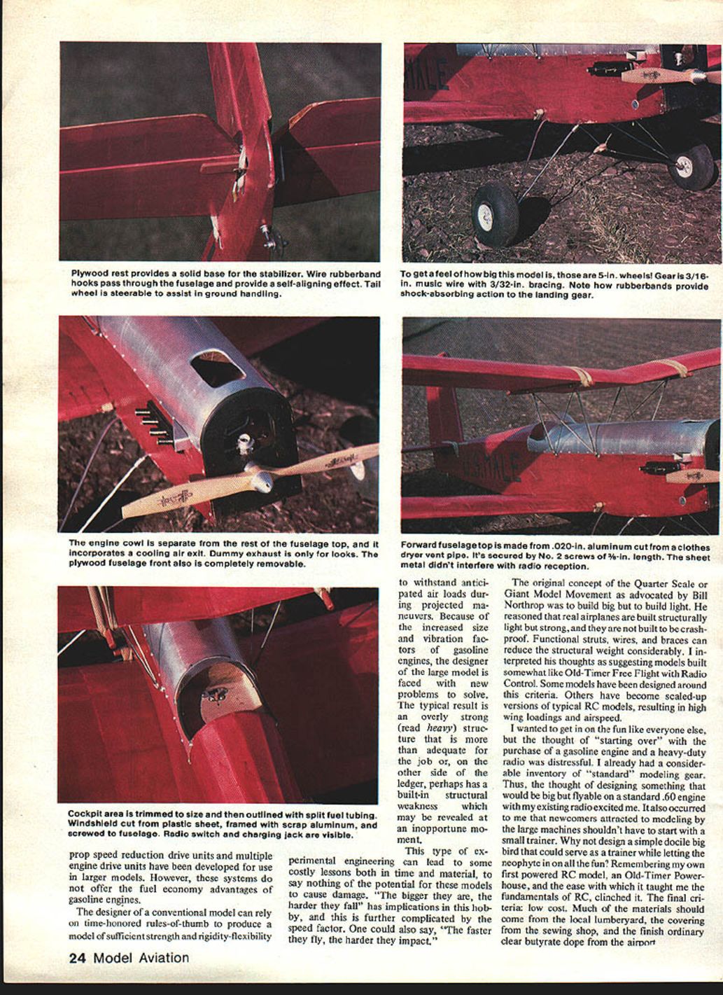
- Note the notch in the bottom of the rudder for the tail-wheel steering arm—this piece is made from hardwood.
- The triangular balsa key on the bottom of the stabilizer is for alignment and must be closely fitted to the fuselage later.
- The base of the fin is notched to clear the top stabilizer spar.
Fuselage
- Cut basic sides and doublers from the 1/8-in. ply door skin.
- Cut formers 3 through 11 from 1/4-in. fir plywood. Former 1 from 1/8-in. aircraft plywood and Former 2 from 3/16-in. fir plywood.
- Clamp fuselage sides together while sanding to final size and fitting the lower-wing cutout to the finished wing.
- Lay out sides with top edges together to ensure one right and one left side. Locate 3/8-in. square pine engine-mount beams using doublers and Formers 3 and 6 for alignment.
- Note: Formers 6 and 8 bear on the fuselage sides while all others rest on doublers.
- Glue engine mounts to sides with white glue and allow to dry. Adhere doublers with contact cement. Ensure space for Former 6 and adhere a tripler to the wing saddle area.
- Glue 3/4-in. square stringers and gussets to the rear-fuselage area. When dry, clamp fuselage sides together outside-to-outside, and drill wing-dowel holes.
- Join fuselage sides using Formers 3, 6, and 8 and the tank-compartment floor to aid alignment. Small nails or brads are helpful and may be left permanently in the structure.
- When dry, install tail-post block and remaining formers. Accurately locate holes for cabane-strut tubes in the fuselage sides and adjacent to Formers 6 and 7. Drill to accept 3/8-in. I.D. brass tubing. Install tubing flush to the outside of the fuselage and secure to formers with wire lacing and epoxy.
- Fabricate landing-gear mounting blocks from 3/16-in. aircraft plywood and install in the notches provided in the fuselage sides.
- Install spruce stringers aft of the cockpit. Add the cockpit floor and servo-mount rails on top of the fuselage tripler.
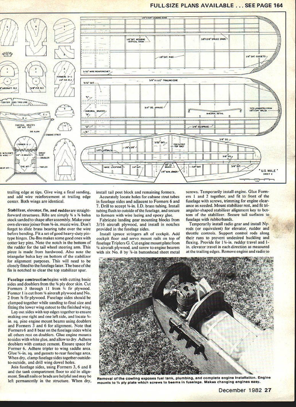
- Cut the engine-mount plate from 1/4-in. aircraft plywood and screw to the engine bearers with six No. 8 x 3/4-in. button-head sheet-metal screws. Temporarily install the engine.
- Glue Formers 1 and 2 together and fit to the front of the fuselage with screws, trimming for engine clearance as needed. Mount the stabilizer rest and fit the triangular stabilizer alignment key to the bottom of the stabilizer. Secure tail surfaces to the fuselage with rubber bands.
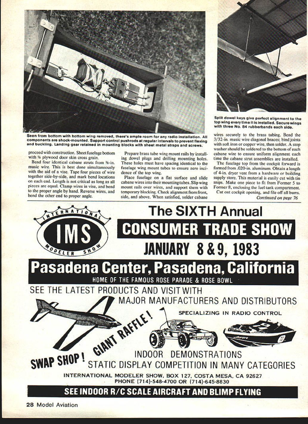
- Temporarily install rudder gear and install Nyrods (or equivalent) for elevator, rudder, and throttle controls. Support control rods along their runs to prevent undesired buckling and flexing.
- Provide for 1/4-in. rudder travel and 1-in. elevator travel in each direction as measured at the trailing edges.
- Remove engine and radio and proceed with the remaining construction. Sheet the fuselage bottom with 1/8-in. plywood door skin, cross grain.
Cabane Struts and Top Wing Mounting
- Bend four identical cabane struts from 3/32-in. music wire. Tape four pieces together side-by-side and mark bend locations on each end. Clamp in a vise and bend to proper angles so all pieces are equal.
- Prepare brass-tube wing-mount rails by installing dowel plugs and drilling mounting holes. These holes must have spacing identical to the fuselage wing-mount tubes to ensure zero incidence of the top wing.
- Place the fuselage on a flat surface and slide cabane wires into their mounting tubes. Slip wing-mount rails over the wires and support them with temporary blocking.
- Check alignment from front, side, and above. When satisfied, solder cabane wires securely to the brass tubing.
- Bend the 3/32-in. music-wire diagonal braces; bind joints with soft iron or copper wire, then solder. Solder a stop washer to the bottom of each cabane wire to ensure uniform alignment each time the cabane-strut assemblies are installed.
Fuselage Top, Cowling, and Cockpit
- The fuselage top from the cockpit forward is formed from .020-in. aluminum. Obtain a length of 4-in. dryer vent material from a hardware or building-supply store; it is easily cut with tin snips. Make one piece to fit from Former 5 to Former 8, enclosing the fuel-tank compartment.
- Cut out the cockpit opening and file off all burrs. Attach the aluminum top to the fuselage with No. 2 x 3/8-in. sheet-metal screws spaced as shown on the plan.
- Cut engine cowling to proportionate length. Provide an engine-cooling hole approximately 1-3/4 x 3/4 in. Also cut clearance for muffler or exhaust extension.
- Cut the windshield from plastic sheet. Frame the bottom edge with scrap aluminum and bolt it to the fuselage.
Landing Gear
- Fabricate the landing gear from 3/16-in. music wire with 3/32-in. music-wire bracing. Fix front- and rear-components to the fuselage with straps and screws. Bind parts together with soft wire and solder securely while assembled to the fuselage.
- Install the tail-wheel gear after covering the fuselage. Remove all metal parts and give the fuselage a final sanding before covering.
Covering
Any of the popular covering techniques can be used. In addition to the flying surfaces, the author prefers to cover the entire fuselage to obtain a lighter-weight finish. In keeping with the budget model, the original was covered with polyester dress lining from the local sewing shop. This material is durable, practically odorless, strong, cheap, and heat-shrinkable. Apply the chosen covering material in the usual manner and finish with clear butyrate dope as desired.
Transcribed from original scans by AI. Minor OCR errors may remain.

