
Valmet Redigo
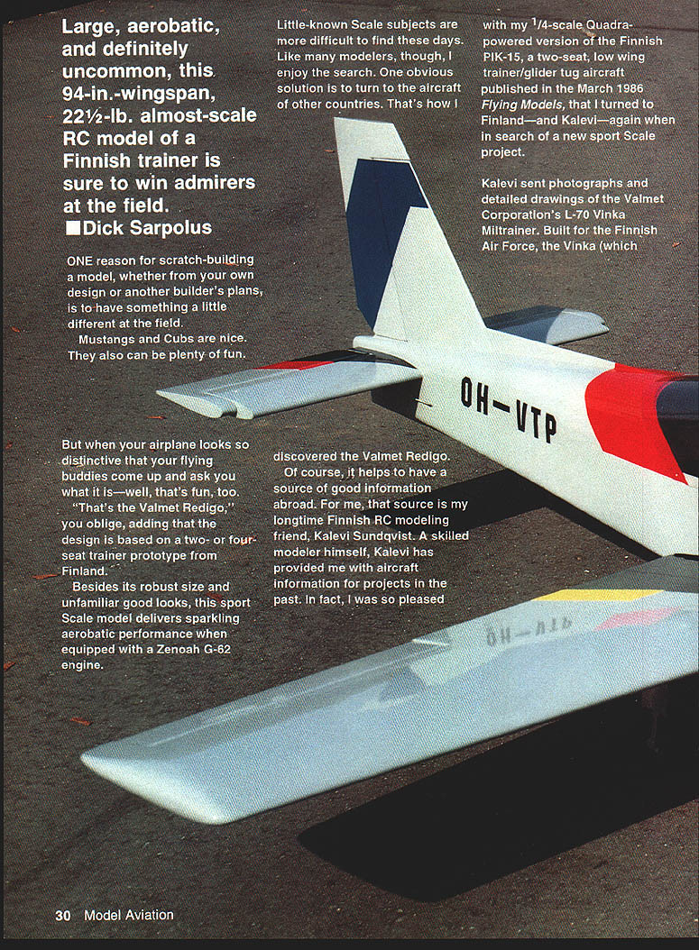
Large, aerobatic, and definitely uncommon, this 94‑in. wingspan, 22 1/2‑lb. almost‑scale R/C model of a Finnish trainer is sure to win admirers at the field. — Dick Sarpolus
One reason for scratch‑building a model, whether from your own design or another builder's plans, is to have something a little different at the field. Mustangs and Cubs are nice. They also can be plenty of fun.
But when your airplane looks so distinctive that your flying buddies come up and ask you what it is—well, that's fun, too. "That's the Valmet Redigo," you oblige, adding that the design is based on a two‑ or four‑seat trainer prototype from Finland.
Besides its robust size and unfamiliar good looks, this sport scale model delivers sparkling aerobatic performance when equipped with a Zenoah G‑62 engine.
Little‑known scale subjects are more difficult to find these days. Like many modelers, though, I enjoy the search. One obvious solution is to turn to the aircraft of other countries. That's how I discovered the Valmet Redigo.
Of course, it helps to have a source of good information abroad. For me, that source is my longtime Finnish R/C modeling friend, Kalevi Sundqvist. A skilled modeler himself, Kalevi has provided me with aircraft information for projects in the past. In fact, I was so pleased with my 1/4‑scale, Quadra‑powered version of the Finnish PIK‑15 (a two‑seat, low‑wing trainer/glider‑tug aircraft published in the March 1986 Flying Models) that I turned to Finland—and Kalevi—again when in search of a new sport‑scale project.
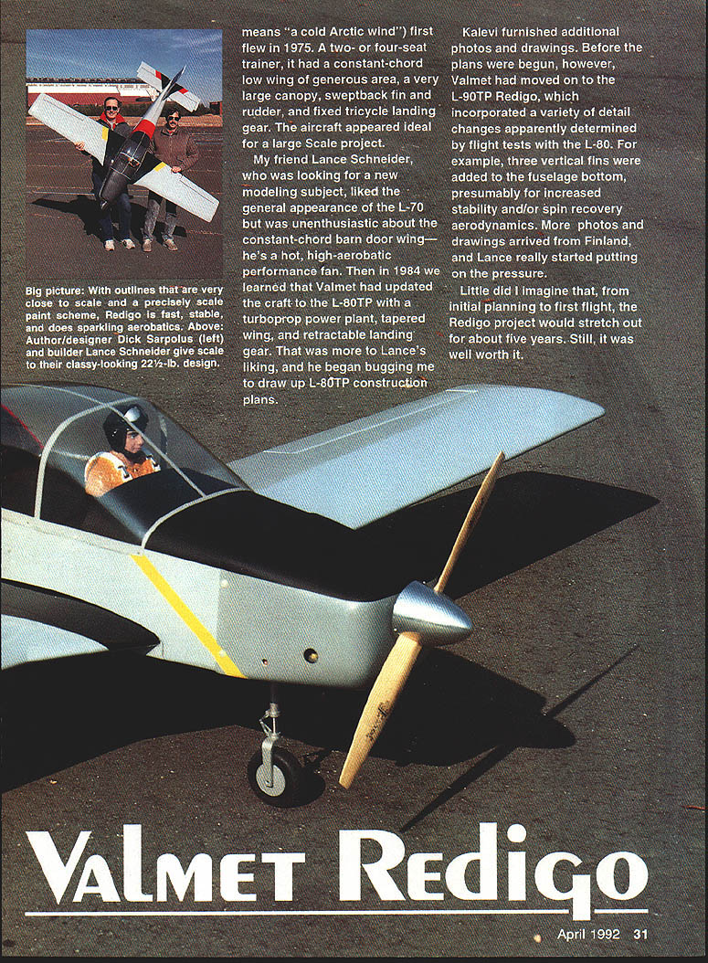
Kalevi sent photographs and detailed drawings of the Valmet Corporation's L‑70 Vinka military trainer. Built for the Finnish Air Force, the Vinka (which means "a cold Arctic wind") first flew in 1975. A two‑ or four‑seat trainer, it had a constant‑chord low wing of generous area, a very large canopy, sweptback fin and rudder, and fixed tricycle landing gear. The aircraft appeared ideal for a large scale project.
My friend Lance Schneider, who was looking for a new modeling subject, liked the general appearance of the L‑70 but was unenthusiastic about the constant‑chord "barn‑door" wing—he's a hot, high‑aerobatic performance fan. Then in 1984 we learned that Valmet had updated the craft to the L‑80TP with a turboprop power plant, tapered wing, and retractable landing gear. That was more to Lance's liking, and he began bugging me to draw up L‑80TP construction plans.
Kalevi furnished additional photos and drawings. Before the plans were begun, however, Valmet had moved on to the L‑90TP Redigo, which incorporated a variety of detail changes apparently determined by flight tests with the L‑80. For example, three small vertical fins were added to the fuselage bottom, presumably for increased stability and/or improved spin‑recovery aerodynamics. More photos and drawings arrived from Finland, and Lance really started putting on the pressure.
Little did I imagine that, from initial planning to first flight, the Redigo project would stretch out for about five years. Still, it was well worth it.
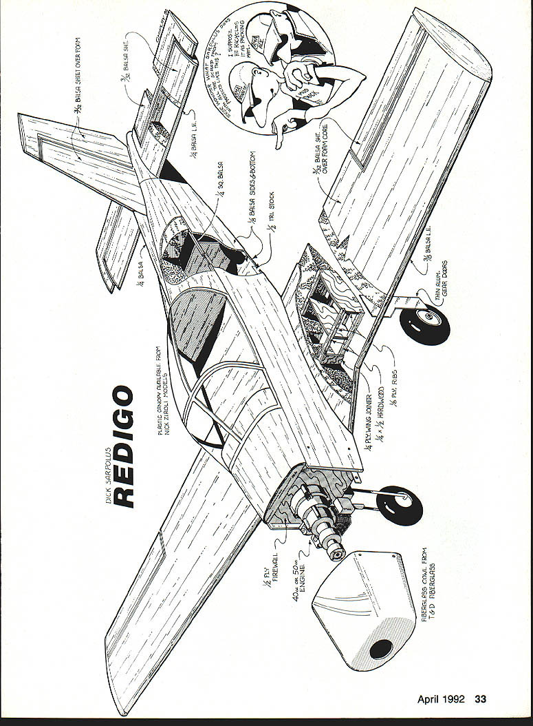
Redigo uses familiar construction techniques well proven on several earlier projects. Experience has shown foam‑cored wing and tail surfaces are the quickest and easiest way to go on scratch‑built models of this size. Foam cores save a great deal of design time and keep the weight at a reasonable figure. I doubt a built‑up rib‑and‑spar/sheet structure of sufficient strength could be achieved at comparable weight. The fuselage configuration, with its straight‑tapered tail section, also lends itself to the use of foam‑cored upper portions.
The design was not difficult to draw. Except for nose length, exact scale outlines were followed as closely as possible. A lighter‑weight choice among available large glow engines could probably keep the nose length at scale proportions. A scratch‑built cowl shape should be fairly easy to duplicate; a fiberglass cowl, however, is available from T & D Fiberglass Specialties, 38624 Mount Kisco, Sterling Heights, MI 48310; telephone 313‑978‑2512.
The full‑scale Redigo uses a modified NACA 63‑218 airfoil at the root and a modified NACA 63‑412 at the tip. The root is set at 3.0° positive incidence and the wing has a built‑in 3.0° washout twist. The drawings in my possession showed the full‑scale airfoils to be too unusual in appearance for an R/C airplane. Instead I drew up a nonscale, fully symmetrical 16%‑thick wing airfoil section similar to those others have used to achieve good aerobatic performance and overall flying characteristics.
For service cutting foam cores available in my area I recommend Aerosmith Model Aviation, RD #1, Box 290, Athens, NY 12015; telephone 518‑945‑1091.
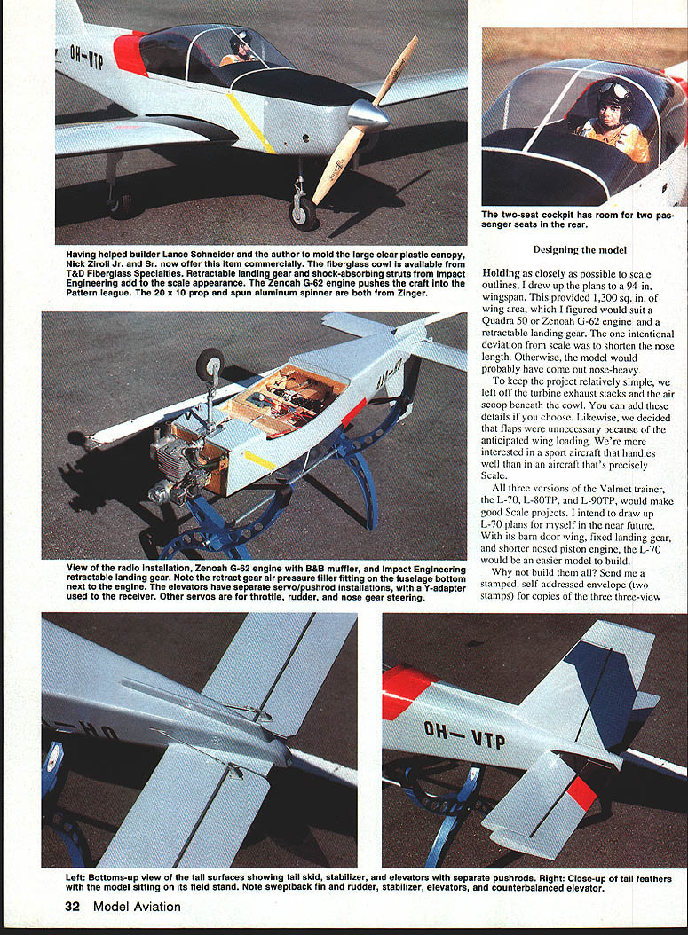
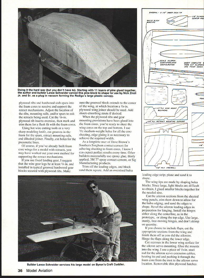
The large clear plastic canopy presents the single most difficult challenge to the scratchbuilder undertaking the project. It is a big one—over 24 in. long, 11 in. wide, and about 6 in. deep—and vacuum‑forming capability of that scope can be hard to find. We were lucky: well‑known modelers Nick Ziroli Jr. and Sr. helped us out with their vacuum‑forming equipment. Lance carved a plug from pine boards glued together (quite a task), which the Zirolis used to pull a few canopies for us. The Zirolis are now offering the canopy commercially; details are available from Nick Ziroli Models, 29 Edgar Drive, Smithtown, NY 11787.
Designing the model
Holding as closely as possible to scale outlines, I drew up the plans to a 94‑in. wingspan. This provided about 1,300 sq. in. of wing area, which I figured would suit a Quadra 50 or Zenoah G‑62 engine and a retractable landing gear. The one intentional deviation from scale was to shorten the nose length; otherwise, the model would probably have come out nose‑heavy.
To keep the project relatively simple, we left off the turbine exhaust stacks and the air scoop beneath the cowl. You can add these details if you choose. Likewise, we decided that flaps were unnecessary because of the anticipated wing loading. We're more interested in a sport aircraft that handles well than in an aircraft that's precisely scale.
All three versions of the Valmet trainer—the L‑70, L‑80TP, and L‑90TP—would make good scale projects. I intend to draw up L‑70 plans for myself in the near future. With its barn‑door wing, fixed landing gear, and shorter‑nosed piston engine, the L‑70 would be an easier model to build.
Send a stamped, self‑addressed envelope (two stamps) for copies of the three three‑view drawings.
I had some doubts about using retractable landing gear. I was concerned about the added weight of the gear mechanisms and the need for more supporting structure, and worried about the reliability of retracts. Also, they do cost some money. But Lance was the builder, so the decision was his. He thought that the clean aircraft layout would look so good and fly so well with the wheels pulled up that retracts were the only way to go.
We found several commercially available retracts that seemed suitable. The Dave Platt and Impact Engineering designs both looked good. We finally used the Impact gear, along with shock‑absorbing struts from the same company, for a scale appearance. The gear appear well designed and operate smoothly. One drawback is the forward location of the actuating cylinder on the nose‑gear unit; Lance machined away a portion of some of the cylinder fins on the Zenoah G‑62 to provide clearance for the retract mechanism. We don't think this will affect the engine. While I can't say the retracts have been completely trouble‑free so far, that's probably because ours was one of the first production sets. The few bugs we ran into are being (or may already have been) worked out.
Lance was right. The plane looks and flies great with the wheels tucked up. If, however, you want to save money and simplify the project, go with fixed gear.
The prototype came out at 22 1/2 lb., for a wing loading of almost 40 oz. per sq. ft. That's a bit high, but models of this size can fly at a higher wing loading and still handle comfortably.
We covered the design with MonoKote, replicating the color scheme of one of the full‑scale test aircraft. Lance plans to give a future Redigo a more striking appearance with a very bright, air‑show type finish that is decidedly nonscale.
We've found the Zenoah G‑62 to be a great engine. Brand new, it turned a 20 x 10 Zinger at 8,400 rpm on the ground, so we expected good flight performance. We weren't disappointed. Its large size notwithstanding, the Redigo is as acrobatic and fast as it is sleek to look at. Stable yet agile, the model flies like a Pattern aircraft with the G‑62. While I'm convinced that a Quadra 50 or even a less powerful engine would deliver reasonable scale performance, the G‑62 turns the plane into a tiger.
Specifications
- Type: Sport Scale
- Wingspan: 94 in.
- Recommended engine size and type: Zenoah G‑62 (40–50cc engine would be adequate)
- Number of R/C channels recommended: Five (six, if using optional flaps)
- Expected flying weight: 22 1/2 lb.
- Type of construction: Built‑up foam‑and‑balsa/plywood
- Type of covering/finish recommended: MonoKote
Construction
Typical sheeted foam‑and‑balsa/plywood built‑up construction is used. The structure is straightforward and uses the fewest parts possible. If you haven't scratch‑built from plans before, be assured that this is a relatively easy project.
Wing
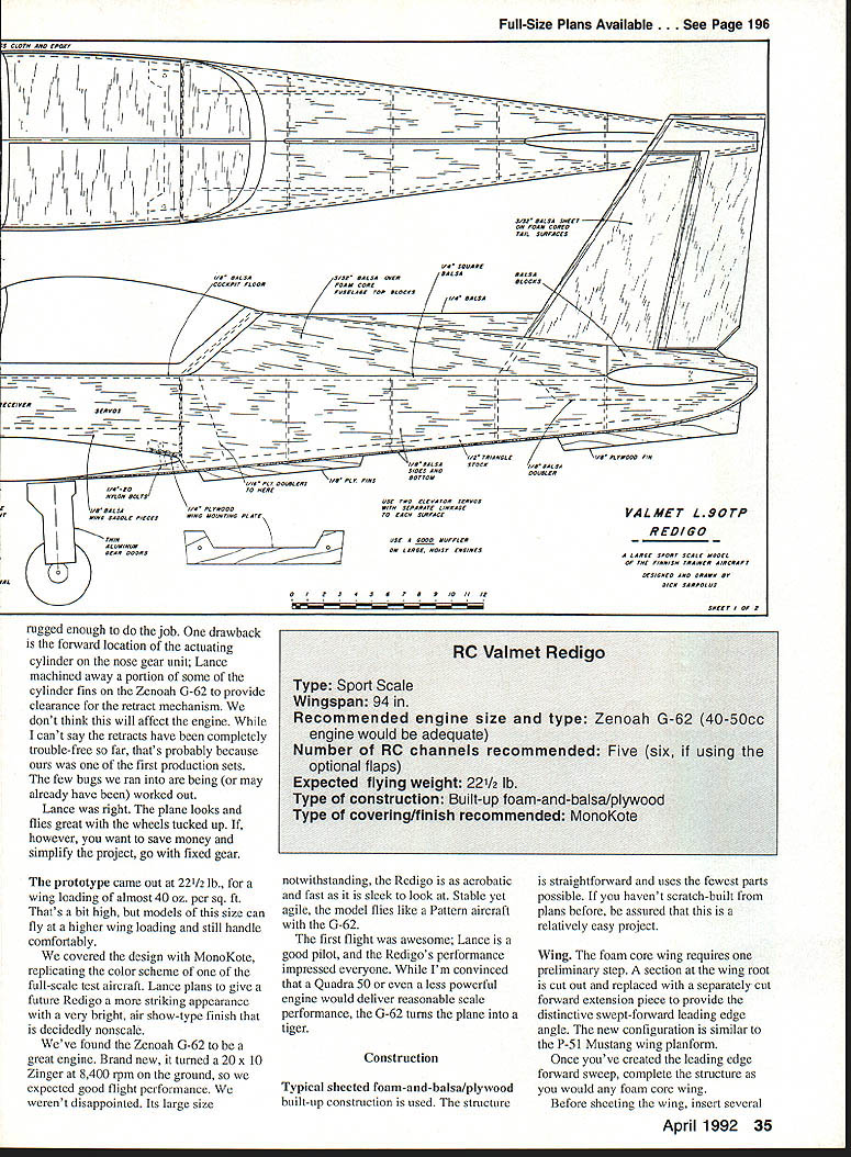
The foam‑core wing requires one preliminary step. A section at the wing root is cut out and replaced with a separately cut forward extension piece to provide the distinctive swept‑forward leading‑edge angle. The new configuration is similar to the P‑51 Mustang wing planform.
Once you've created the leading‑edge forward sweep, complete the structure as shown and you're ready to finish the foam‑core wing. Glue plywood ribs and hardwood stub spars into the foam cores to receive and support the retract mechanisms. Adjust the location of the ribs, mounting rails, and/or spars to suit the retracts being used. Cut the 1/8‑in. plywood rib inserts oversize, then mark and trim them for a flush fit with the foam cores.
Using hot‑wire cutting tools or a very sharp modeling knife, cut grooves in the foam for the spars, retract mounting rails, and dihedral joiner. Finally, cut holes for the pneumatic lines.
If you use fixed landing gear, I suggest that the wire gear legs be at least 1/4 in. and installed in typical grooved hardwood gear blocks secured with plywood ribs. Make sure the grooved block extends to the center of the wing, at which location a 1/4‑in. plywood wing joiner should be used. Add shock‑absorbing struts if desired.
When the plywood ribs and gear mounting provisions have been glued into the foam cores, sheet the wing cores on the top and bottom. Use 3/32‑in. medium‑weight balsa for all the core sheeting, edge‑gluing it as necessary to achieve the required width.
I have long used Dave Brown's Southern Sorghum contact cement for adhering sheeting to foam cores and expect perfect results. Other builders successfully use epoxy (thinly applied), 3M 77 spray contact cement, or Sig Manufacturing products.
Trim off the leading edges and block‑sand them square. Add an oversized balsa leading‑edge strip; plane and sand it to shape.
The wingtips are made by shaping balsa blocks. Since large, light blocks are difficult to obtain, glue smaller blocks together for the needed size.
Cut the aileron sections from the sheeted wing panels, trim them down to allow for the balsa edging, and sand the edges to shape. Bevel the aileron leading edges in preparation for hinging. Install the hinges either along the centerline, as in the prototype, or along the top edge. Use large, sturdy, free‑moving hinges, and don't skimp on quantity.
If you choose to include flaps, cut the appropriate sections from the wing and finish them as you did the ailerons. Hinge the flaps along the lower edge.
Cut recesses in the lower wing surface for the aileron servo mounting and glue the mounts into the wing. I use a piece of 1/4‑in. steel rod for the aileron servo extension cables, heating its end and pushing it through the foam core from the root to the aileron servo location. Removable thin plywood hatches give access to the servos.
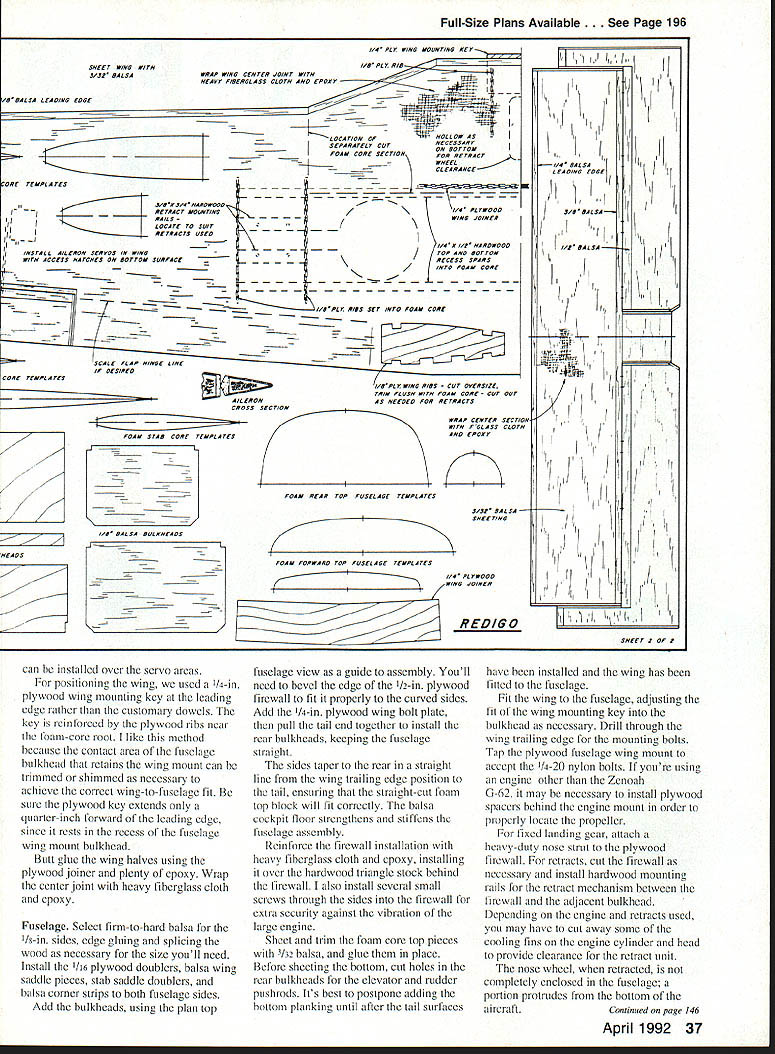
For positioning the wing, we used a 1/4‑in. plywood wing‑mounting key at the leading edge rather than customary dowels. The key is reinforced by the plywood ribs near the foam‑core root. I like this method because the contact area of the fuselage bulkhead that retains the wing‑mount cap can be trimmed or shimmed as necessary to achieve the correct wing‑to‑fuselage fit. Be sure the plywood key extends only 1/4 in. forward of the leading edge, since it rests in the recess of the fuselage wing‑mount bulkhead.
Glue the wing halves using the plywood joiner and plenty of epoxy. Wrap the center joint with heavy fiberglass cloth and epoxy.
Fuselage
Select firm‑to‑hard balsa for the 1/8‑in. sides, edge‑gluing and splicing the wood as necessary for the size you'll need. Install the 1/16‑in. plywood doublers, balsa wing‑saddle pieces, stab‑saddle doublers, and balsa corner strips to both fuselage sides.
Add the bulkheads, using the plan top‑fuselage view as a guide to assembly. You'll need to bevel the edge of the 1/2‑in. plywood firewall to fit it properly to the curved sides. Add the 1/4‑in. plywood wing bolt plate, then pull the tail end together to install the rear bulkheads, keeping the fuselage straight.
The sides taper to the rear in a straight line from the wing trailing‑edge position to the tail, ensuring that the straight‑cut foam top block will fit correctly. The balsa cockpit floor strengthens and stiffens the fuselage assembly.
Reinforce the firewall installation with heavy fiberglass cloth and epoxy, installing it over the hardwood triangle stock behind the firewall. I also install several small screws through the sides into the firewall for extra security against the vibration of the large engine.
Sheet and trim the foam‑core top pieces with 3/32‑in. balsa, and glue them in place. Before sheeting the bottom, cut holes in the rear bulkheads for the elevator and rudder pushrods. It's best to postpone adding the bottom planking until after the tail surfaces have been installed and the wing has been fitted to the fuselage.
Fit the wing to the fuselage, adjusting the fit of the wing‑mounting key into the bulkhead as necessary. Drill through the wing trailing edge for the mounting bolts. Tap the plywood fuselage wing mount to accept the 1/4‑20 nylon bolts. If you're using an engine other than the Zenoah G‑62, it may be necessary to install plywood spacers behind the engine mount in order to properly locate the propeller.
For fixed landing gear, attach a heavy‑duty nose strut to the plywood firewall. For retracts, cut the firewall as necessary and install inboard mounting rails for the retract mechanism between the firewall and the adjacent bulkhead. Depending on the engine and retracts used, you may have to cut away some of the cooling fins on the engine cylinder head to provide clearance for the retract unit.
Note: the nose wheel, when retracted, is not completely enclosed in the fuselage; a portion protrudes from the bottom of the aircraft.
The fiberglass cowl is trimmed as necessary to clear the engine cylinder, exhaust, and landing gear. Tap the fuselage sides for threaded nylon bolts to be used in mounting the cowl.
With the wing bolted to the fuselage, build up a lower section, glue it to the wing bottom, and shape it to blend into the rear fuselage section. Similarly, shape a balsa block to contour with the bottom forward fuselage, and glue it to the bottom of the wing.
Trim the large plastic canopy to fit, then secure it with small screws to the lower edges of the fuselage sides. Add simulated interior cockpit details to suit. Since the Redigo is set up for two‑person side‑by‑side seating with room for two rear passenger seats, up to four figures could be used for extra realism.
Tail surfaces
Sheet the tail surface cores with 3/32‑in. balsa. Join the horizontal stabilizer panels, reinforcing the joint with fiberglass cloth and epoxy. Cut the surface apart along the hinge lines, allowing space for the added balsa edges. Finish off the edges, install the hinges, and glue the stabilizer into the fuselage.
Glue the vertical fin to the stabilizer and into the top fuselage piece. The rudder linkage can be handled with a torque‑tube arrangement extending through the stab; since the hookup to the pushrod will be internal, be sure to make it secure.
Shape the balsa blocks to be installed aft of the fuselage top on each side of and behind the fin. When the blocks are in place, make the three small fixed vertical fins and attach them to the fuselage bottom.
Control surfaces
Recess the control surfaces to accept 1/4‑in. plywood pieces for mounting the nylon horns to the ailerons and elevators. Epoxy the plywood mounts into the control surfaces, and attach the horns with small screws. I recommend using the larger 4‑40 threaded rods and clevises for all linkages. Use fiberglass‑tube pushrods for the elevator linkages.
Make the fuselage servo mounting from 1/4‑in. plywood. The elevators are actuated by separate servos, each with its own pushrod. This allows the pushrods to be perfectly straight. Since the pushrods cross over within the fuselage, one of the elevator servos must be mounted about 3/8 in. higher than the other to prevent the pushrods from rubbing together.
Use Airtron extension cables to make a Y‑harness for the two aileron servos mounted in the wing. Another Y‑harness is required for the two elevator servos.
We used a 1,200‑mAh battery pack wrapped in foam rubber. It is positioned behind the wing trailing edge, where its weight is required for balance.
Landing gear, wheels, engine, and fuel system
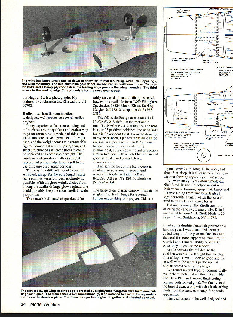
For appearance's sake, we cut the main landing‑gear doors from thin aluminum and attached them to the retract struts with silicone adhesive. We may add landing‑gear doors for the nose gear as well. Robart's scale wheels look good on this model. To adequately support the Redigo's weight, however, the wheels require Robart's internal foam tire "doublers." Order these direct from the manufacturer.
We used a 16‑oz. fuel tank. There's room for a second 16‑oz. tank for a smoke system, if desired. The ignition cutoff switch is mounted forward of the firewall; the switch handle protrudes slightly through the fiberglass cowl.
The propeller is a Zinger 20 x 10, used with a Zinger 3‑1/2‑in. spun aluminum spinner.
Cut a hole through the cowl for easy access to the carburetor. Install the air‑pressure filler valve for the retracts in the fuselage bottom nose section.
We used a B&B muffler on the Zenoah G‑62, cutting the cowl for clearance around the muffler. Unfortunately, the noise level is still pretty high. I don't know of any really effective commercially available mufflers that fit the G‑62, but add‑on units such as the J‑Tec Snuffler could be hung externally below the fuselage. It wouldn't look so good, but unless your flying field location can tolerate the noise, you might have to quiet that Zenoah somehow.
Covering and finishing
We duplicated the color scheme of one of the original Redigo test aircraft—gray overall with contrasting areas of black, red, yellow, and blue. The look is scale, yet somewhat understated. As noted, our next Redigo will probably receive a bright, air‑show, aerobatic‑type finish for greater visual excitement.
This is a large airplane with a large engine. While not exact scale, it comes pretty close. Using retracts adds to the complexity, and the amount of scale detailing incorporated is up to the builder. Basically, however, you can count on an airframe that's not only quick and easy to build but fast and acrobatic in flight. Redigo is well suited to the sport flier who wants a large model with hot performance.
Transcribed from original scans by AI. Minor OCR errors may remain.

