
Variable-Camber Wings
Robert Fiorenze
Adding scale detail such as variable-camber wings can be easier than you'd think.
What scale builder doesn't want to duplicate every feature of his full-size prototype? In some cases that's a difficult, impractical goal, but in other cases it's more easily achieved.
My latest scale project, a Yellow Aircraft F-18 Hornet, had competed successfully without the installation of operable wing flap and leading-edge slat systems. However, competition had since evolved to the point that the extra gadgetry became almost a requirement.
The problem of how to change the wings to variable camber raised some interesting aerodynamic questions. For help, I turned to a friend, aerospace engineer Mickey Nowell. I followed his advice on designing the flap and slat system. Static testing results convinced me that the system was practical. I was mainly concerned about what would happen to the leading-edge slats during inverted flight.
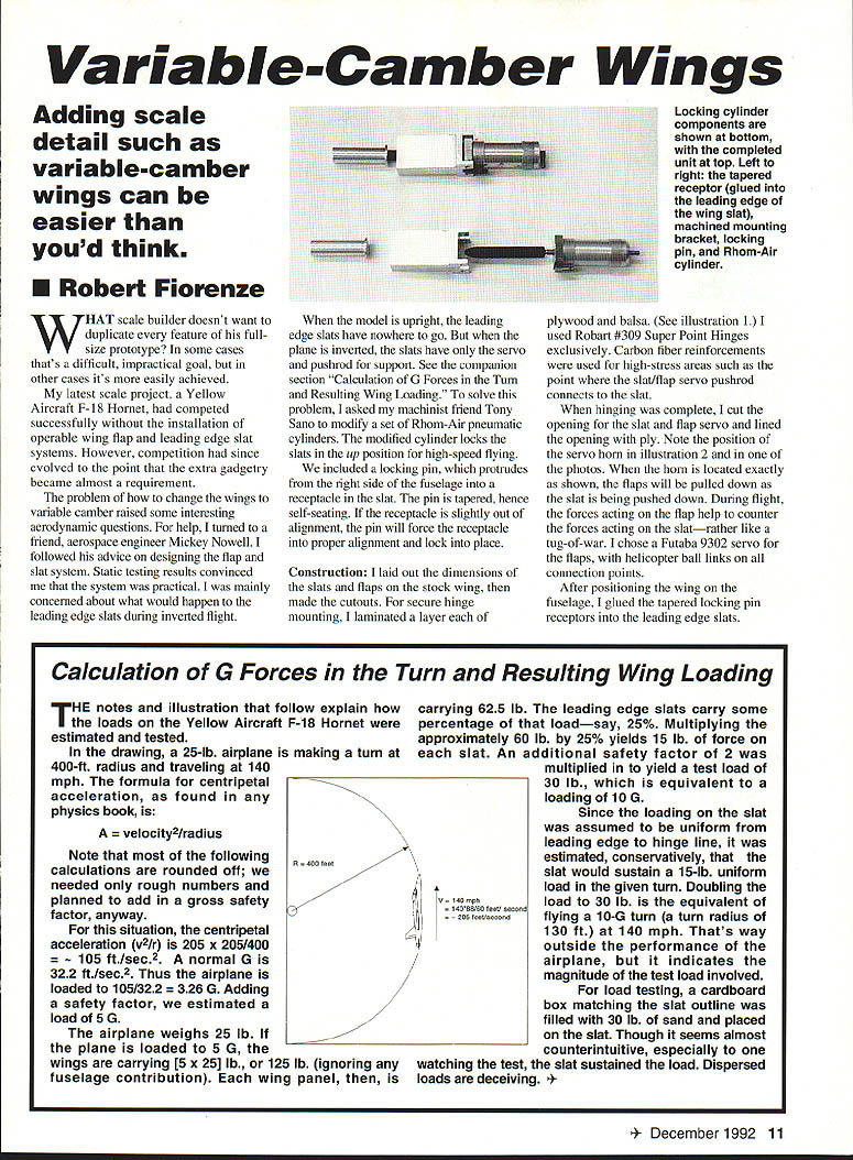
When the model is upright, the leading-edge slats have nowhere to go. But when the plane is inverted, the slats have only the servo and pushrod for support. (See the companion section "Calculation of G Forces in the Turn and Resulting Wing Loading.") To solve this problem, I asked my machinist friend Tony Sano to modify a set of Rhom-Air pneumatic cylinders. The modified cylinder locks the slats in the up position for high-speed flying.
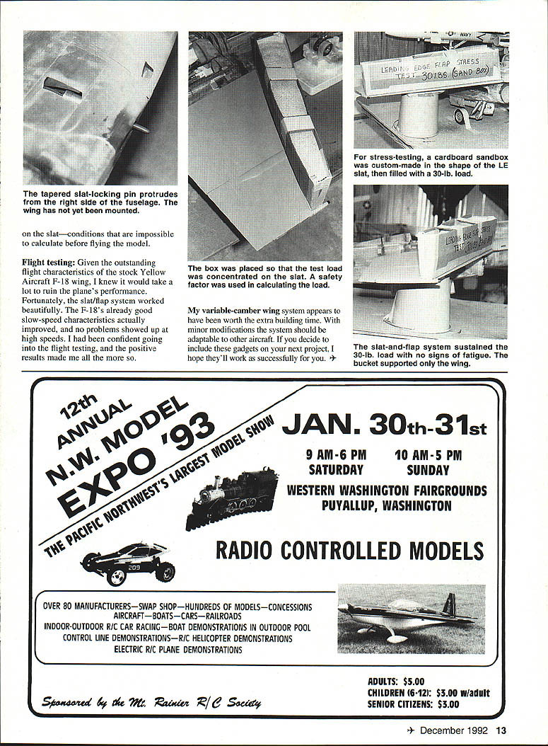
We included a locking pin that protrudes from the right side of the fuselage into a receptacle in the slat. The pin is tapered, hence self-seating. If the receptacle is slightly out of alignment, the pin will force the receptacle into proper alignment and lock into place.
Construction
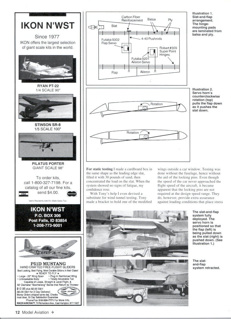
I laid out the dimensions of the slats and flaps on the stock wing, then made the cutouts. For secure hinge mounting, I laminated a layer of plywood and a layer of balsa. (See illustration 1.) I used Robart #309 Super Point Hinges exclusively. Carbon-fiber reinforcements were used for high-stress areas such as the point where the slat/flap servo pushrod connects to the slat.
When hinging was complete, I cut the opening for the slat and flap servo and lined the opening with ply. Note the position of the servo horn in illustration 2. When the horn is located exactly as shown, the flaps will be pulled down as the slat is being pushed down. During flight, the forces acting on the flap help to counter the forces acting on the slat—rather like a tug-of-war. I chose a Futaba 9302 servo for the flaps, with helicopter ball links on all connection points.
After positioning the wing on the fuselage, I glued the tapered locking-pin receptacles into the leading-edge slats.
Calculation of G Forces in the Turn and Resulting Wing Loading
The notes and illustration that follow explain how the loads on the Yellow Aircraft F-18 Hornet were estimated and tested.
In the drawing, a 25-lb. airplane is making a turn at a 400-ft. radius and traveling at 140 mph. The formula for centripetal acceleration is:
A = velocity^2 / radius
Note that most of the following calculations are rounded off; we needed only rough numbers and planned to add a gross safety factor, anyway.
For this situation, the centripetal acceleration (v^2/r) is 205 x 205 / 400 = 105 ft./sec.^2. A normal G is 32.2 ft./sec.^2. Thus the airplane is loaded to 105 / 32.2 = 3.26 G. Adding a safety factor, we estimated a load of 5 G.
The airplane weighs 25 lb. If the plane is loaded to 5 G, the wings are carrying (5 x 25) lb., or 125 lb. (ignoring any fuselage contribution). Each wing panel, then, is carrying 62.5 lb. The leading-edge slats carry some percentage of that load—say, 25%. Multiplying the approximately 62.5 lb. by 25% yields 15 lb. of force on each slat. An additional safety factor of 2 was multiplied in to yield a test load of 30 lb., which is equivalent to a loading of 10 G.
Since the loading on the slat was assumed to be uniform from leading edge to hinge line, it was estimated, conservatively, that the slat would sustain a 15-lb. uniform load in the given turn. Doubling the load to 30 lb. is the equivalent of flying a 10-G turn (a turn radius of 130 ft.) at 140 mph. That's well outside the performance of the airplane, but it indicates the magnitude of the test load involved.
For load testing, a cardboard box matching the slat outline was filled with 30 lb. of sand and placed on the slat. Though it seems almost counterintuitive, especially to one watching the test, the slat sustained the load. Dispersed loads are deceiving.
With Tony's help I even devised a substitute for wind-tunnel testing. Tony made a bracket to hold one of the modified wings outside a car window. Testing was done without the fuselage, hence without the aid of the locking pins. Even though the speed of the car never approached the flight speed of the aircraft, it became apparent that the locking pins are not required at the design speed range. They do, however, provide extra assurance against loading conditions that place stress on the outboard skins and ribs and on the slat—conditions that are impossible to calculate before flying the model.
Flight testing
Given the outstanding flight characteristics of the stock Yellow Aircraft F-18 wing, I knew it would take a lot to ruin the plane's performance. Fortunately, the slat/flap system worked beautifully. The F-18's already good slow-speed characteristics actually improved, and no problems showed up at high speeds. I had been confident going into the flight testing, and the positive results made me all the more sure.
My variable-camber wing system appears to have been worth the extra building time. With minor modifications the system should be adaptable to other aircraft. If you decide to include these gadgets on your next project, I hope they'll work as successfully for you.
Transcribed from original scans by AI. Minor OCR errors may remain.

