
Variant
Clarence Mather
Overview
The Bostonian event is ideal for fliers who like small sport models: easy to build, semiscale in appearance, capable of good flights, and suitable for flying in small gyms. Models are rubber powered and must meet the event specifications below.
Bostonian Event Rules (highlights)
- Wingspan: maximum 16 in.
- Chord: maximum 3 in.
- Fuselage length: maximum 14 in.
- Prop diameter: maximum 6 in.
- Minimum fuselage "box" volume must enclose 3 x 2 x 1½ in.
- At least two wheels, minimum diameter 3/4 in.
- Fuselage must have a front and two side windows, minimum area 1 sq. in.
Weight rules originally specified a minimum model weight of 7 grams. Walt Mooney and the Scale Staffel of San Diego advocate a 14-gram minimum as more practical—especially for less experienced builders—because the heavier model is stronger, more durable, and easier to finish attractively for indoor or outdoor flying.
Design concept
I chose a canard configuration for Variant for several reasons:
- The rubber motor can run the full fuselage length for maximum turns.
- The fuselage "box" side area can be located rearward to provide fin action.
- Canards are inherently stable and fly well as small rubber models.
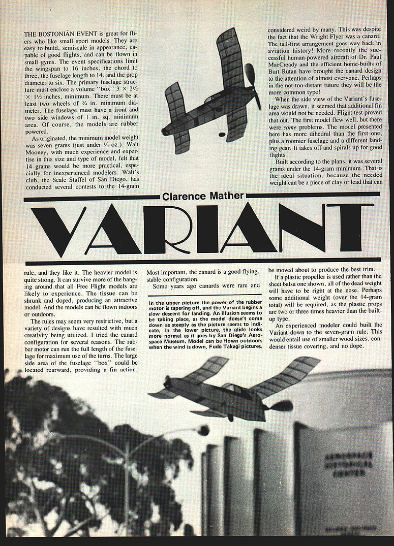
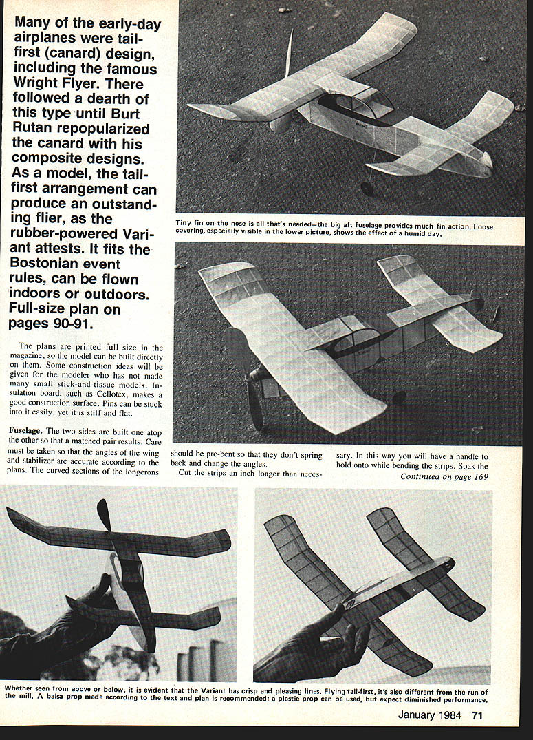
Historically canards were uncommon despite early examples such as the Wright Flyer. Recent successful full-size designs (e.g., Paul MacCready, Burt Rutan) have renewed interest in the configuration.
The Variant in brief
- The Variant uses more dihedral and a roomier fuselage than my first canard attempt, and has a different landing gear.
- It takes off and spirals up for good flights.
- Built to plan dimensions it came in several grams under 14 g, which is ideal: you can add movable clay or lead to achieve best trim.
- If a plastic prop is used (rather than the built-up balsa prop), expect additional nose weight because plastic props are typically 2–3 times heavier.
Full-size plans are printed in the magazine (pages 90–91), so the model can be built directly from them. Use a flat construction surface such as insulation board (e.g., Cellotex); pins stick easily and the board is stiff and flat.
Construction
#### Fuselage
- Build the two fuselage sides one atop the other so you get a matched pair.
- Care is required to ensure wing and stabilizer angles match the plans. Pre-bend the curved sections of the longerons so they do not spring back and change angles. Cut the strips an inch longer than needed to give a handle for bending.
- Soak the strips and scrap pieces in water for an hour or so before forming. To bend, you can draw the wet pieces across a partially heated soldering iron, applying steady pressure; practice first on scrap. Dip stubborn pieces in water between draws.
- Build the rear fuselage continuously up through the motor-tube area; part will later be removed where the tube fits. Note the longerons are actually longer than the side view suggests because the rear is bent sharply to a point.
- Use two simple jig formers (rectangular sheet-balsa pieces that fit between the sides) to help produce an accurate fuselage. Form a box of the two sides and the formers; while glue is still soft, set the box over the top view to check alignment.
- When glue hardens, notch the inside of the longerons where sharp bends occur, crack the longerons at the bend, fill notches with glue, and pin the rear together. Recheck alignment with the top view.
- Cut and glue front crosspieces. Hold the sides against the crosspieces by sliding a bottle in from each side while glue sets. Add all crosspieces, nose block, landing gear, etc.
- Leave slots for wing and stab rectangular until flight testing is complete so incidence adjustments can be made. Remove jig formers after fitting.
#### Motor tube
- Cut a rectangular piece of thin balsa for a 1/2-in. motor tube (a 1/2-in. drill shank makes a good former). Sand sheet thinner if necessary (not less than 1/64 in.). Soak the sheet overnight, lash to the former with a narrow cloth strip, and bake at 250°F for an hour. Glue the seam.
- Cut the V-slot so the tube fits over the rear of the fuselage. Pencil around the tube where it contacts the fuselage, cut away the fuselage inside the tube to within 1/16 in. of the pencil mark, and glue the tube in place. The 1/2-in. tube allows use of a winding tube to protect the fuselage during winding.
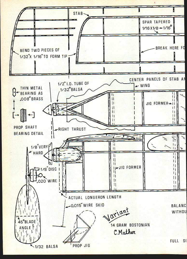
#### Propeller
- Blades: cut from 3/32-in. sheet balsa (can be sanded thinner). Soak overnight, lash to a large coffee can with tips skewed about 15° left, and bake at 250°F for an hour. Use very hard balsa for blades; the hub center should be about 1/8 in. or larger in diameter. Taper the spar to points from the center.
- Prop jig: make an upright piece for the shaft and a 45° piece for the blade. Glue the two vertical uprights to a base 1¼ in. apart—this gives roughly an 11-in. pitch.
- Sharpen one end of the prop-shaft wire and push it through the center of the prop spar (do not glue immediately). Slot the blades to accept the spar. Glue one blade to the spar, and while the glue is soft, set it on the jig with the shaft held to the upright and the blade against the 45° piece. When set, complete the other half.
- Motor-tube plug: make of two 1/8-in. balsa discs glued crossgrain. The smaller disc should be a snug fit in the tube; the larger overlaps the tube.
- If you must penetrate thin metal bearings and lack a small drill, pins can punch holes through the metal (hammer just enough that the shaft can spin freely). Put the burr side against the balsa when gluing through the bearing to the plug. Slide the shaft through the plug; a small washer or glass bead may be used but a good glue shoulder suffices. Slide the prop on the shaft and bend the end over; glue securely. Build up a glue shoulder inside the hub by applying several coats; as each coat begins to harden, use a razor to push the glue into a flat shoulder around the shaft.
#### Front anchor and stringing
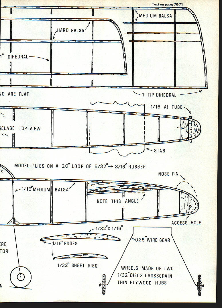
- A 1/16-in. or 3/32-in. aluminum tube makes a good anchor peg for the front of the rubber. Cut a small hole in the underside of the nose so you can see to string the motor.
#### Wing and stabilizer (stab)
- Make the stabilizer edges and spar from hard balsa since the front-mounted stab will be prone to collision forces. A tapered spar adds strength to the fuselage–stab joint. Tips are made from two laminations for added rigidity.
- Shape ribs from a stack of rectangular pieces: cut pieces slightly oversize, trace the rib outline on two outer pieces, stack like a deck of cards, and shape the entire stack to the outline including the spar notches. For the stab, taper the spar notch from one end to the other.
- Make center panels with top spars in place, allowing spars to extend 1/8 in. beyond the end rib. Let glue set thoroughly to reduce warping.
- Assemble tip sections without spars, glue them to center sections with tips propped up for dihedral, then add spars for a good fit into the center panels.
#### Covering and finishing
- Check surfaces carefully for warps before covering. If warped, use a jet of steam and twist opposite the warp to correct it.
- Cover with lightweight tissue, water-shrink, and as the tissue dries give the center panels a flat surface to resist warping. Apply one or two thin coats of nitrate dope to tauten tissue (or one coat, taking care about moisture). Steam treatment can also remove warps from covered surfaces.
- Leave the fuselage area above the wing and stab uncovered until flight testing is completed so adjustments are easy.
Flying and trimming
- Glue the wing and stab lightly in position for initial tests. Check the balance point and add clay or lead to the nose or tail to reach the location shown on the plans. The original Variant flew to the right (against torque) and required a few degrees of right thrust. The end of the motor tube is angled to change thrust.
- For first tests, make a motor that just reaches from the prop hook to the peg; it can be hand-wound easily for quick trials. Wind about 100 turns and launch in level flight with a slightly underhand, not-too-fast throw. Only small corrections are normally needed.
- Adjustments:
- Diving tendency: cut the leading edge of the stab free, prop it up to the required incidence and glue or CA it in place. Small changes may be made with an IBM tab card.
- Model that stalls and flies straight: increase offset thrust to tighten the turn.
- Long stalling period: the model may descend slowly while the motor runs; the landing may appear shallower than it really is.
- Plastic propellers: if used instead of the built-up balsa prop, expect more nose dead weight and possibly the need for additional total model weight. Plastic props are typically 2–3 times heavier.
- An experienced modeler could reduce Variant to the original 7-gram rule by using smaller wood sizes, denser tissue covering, and omitting dope.
Tips and anecdotes
- For ROG (rise-off-ground) flying, large empty parking lots in the early dawn are excellent. Be mindful of buildings and obstacles—light thermals can carry a model onto roofs or other hard-to-reach places. You may meet interesting people while flying; one anecdote: a store manager retrieved a model from his roof and turned out to be a former modeler himself.
Suppliers
If local hobby shops do not stock parts for models like Variant, two reliable mail-order suppliers are:
- Oldtimer Models, P.O. Box 913, Westminster, CA 92683
- Peck-Polymers, P.O. Box 2498, La Mesa, CA 92041
Plans
Full-size plans are printed in the magazine (see pages 90–91) so the model can be built directly from them.
Transcribed from original scans by AI. Minor OCR errors may remain.

