
Vertical Tail Size for Models
William F. McCombs
One key to optimal flight stability is tailoring your model's vertical tail, both during the design stage and after initial flight testing. In this conclusion of a two-part article, the author explains what to look for, how to correct problems, and more.
Overview
Part One discussed the combined influence of vertical tail size and total effective dihedral on a model's stability in flight — and, for piloted airplanes, the influence of vertical tail size on in-flight controllability. This conclusion explains how to adjust vertical tail size to correct problems that show up in flight, how to achieve a reasonable vertical tail area during the design stage, and the relationships among turning trim, wing dihedral, and effective dihedral. A summary and appendices follow.
Tailoring the tail
There are two cases: an existing model that has been flown and is troublesome, and a new, unflown model.
1. Existing troublesome model
Proceed as follows, or follow (2) below.
- If the model shows wandering flight, insensitivity to small side thrust or tail-incidence changes, or a mild to severe Dutch roll:
- Glue on a small additional amount of vertical tail area — about 5% of the existing area — and fly again.
- Repeat as necessary until the trouble disappears.
- If the model's turning flight is overly sensitive to small side thrust or tail-incidence changes, or if an initial burst of power (as in rubber models) causes a roll-off into an undesired spiral:
- Cut away a little vertical tail area — about 5% of the existing area — and fly again.
- Repeat as necessary until the trouble disappears.
- Ensure trim is adequate and there is a minimum dihedral for Free Flight Scale (FFS) models. Hinging the rudder portion is often adequate.
2. New, unflown model
The goal is to get approximately the right tail size before powered flights to avoid early damage.
- Start with a sheet-balsa tail and trim the model for a good, straight (no turning), slow hand-launched glide (no stalling). Launch from a good height (standing on a table or a car) for a longer glide.
- To better detect any Dutch roll, launch the model into its glide with the wing banked about 40° (for example, left wing down). When properly launched, the model should quickly roll out of its bank and then glide straight. If it then turns to the right and alternates right-left, Dutch roll is present.
- If Dutch roll appears, glue on a small amount of tail area between successive glides (about 5% increments) until it disappears.
- If no Dutch roll is seen, cut away tail area in small amounts (about 5% of the existing area) between successive glides until Dutch roll is detected, then eliminate it as above. This yields a near-correct tail size for initial powered flights.
- After finalizing with the sheet-balsa tail, you can replace it with a built-up tail if desired.
Notes:
- For rubber models, fix the prop in the vertical position for glide tests if it doesn't freewheel or fold. If it folds, or if the model glides with very low power in straight-level or descending flights, the same banked-launch test is acceptable.
- For a new FFS model, another approach is to do the above tests with the rudder portion removed. If little or no Dutch roll appears, the model will likely be acceptable with the rudder removed. If Dutch roll appears later, enlarge the fin by making any horn area part of the fin and, if needed, increase the fin area in small increments until it disappears. A floating (hinged) rudder also allows Old-Timer free-flight models with large tails to climb more steeply if desired.
About turning trim
A bad spiraling may be due to incorrect trim rather than to spiral instability. Spiral instability is indicated when trim changes won't correct the spiraling.
- Too much turning trim will cause a tight turn, excessive banking, and a spiral dive. Such a tight turn is desirable for indoor flying.
- Historically, wing warping was used to keep the wing level in a turn by washin — warping the trailing edge of the inside wing down slightly (e.g., the left wing trailing edge down a little for a left turn). About 1/30 wing-tip washin (roughly 1–3° at the wing tip, depending on desired turn tightness) was used.
- Non-scale indoor models typically offset the wing slightly to the left for a left turn — about 3–5% of the wingspan — instead of using wing warping.
- Using a tilted stabilizer setting instead of vertical tail or rudder incidence produces a gliding slow cruising turn preferred for non-scale models; this effect essentially disappears during high-powered flight. For powered flight, the turn is trimmed with side thrust (and often fine-tuned with a small tail tab), and downthrust is adjusted to get the desired climb.
- When a model has been trimmed to turn in one direction using wing warping or wing offset, do not attempt to make it fly the other direction without first removing the warping or offset; otherwise it will spiral and likely crash.
- High-powered, steep-climbing free-flight duration models must be launched pointed steeply upward; otherwise they usually dive in and crash before attaining climb attitude.
Wing dihedral and effective dihedral
Effective dihedral is anything that produces the same rolling effect as wing dihedral when the model is in a sideslip (a yawed attitude). The main sources of effective dihedral for FFS models are:
- Wing position
- A high wing generates about +1° to +3° of effective dihedral.
- A midwing generates about 0°.
- A low wing generates about −1° to −3°.
- For many Scale and full-scale airplanes a reasonable assumption is +2° for high wings and −2° for low wings (a formula for a closer estimate is in Appendix A). The effect is negligible for models with slim noses.
- Wing tip shape
- If, in front view, the lower surface slants upward to meet the upper surface (mild), about +0.5° of effective dihedral is generated.
- If the upper surface slants downward to meet the lower surface, about −0.5° is generated.
- If both surfaces slant, or the tip is blunt/rounded, no effective dihedral is generated.
- These values apply for low-speed flight and lessen as trimmed lift speed increases.
- Wing aspect ratio (AR = wingspan ÷ average chord)
- Typical low-speed effective dihedral by aspect ratio:
- AR 1½ → 3°
- AR 2 → 2°
- AR 2½ → 1½°
- AR 3 → 1°
- AR 3½ → ¾°
- AR 4 → ½°
- AR 4½ → ⅓°
- AR 5 → ¼°
- AR 5½ → 1/6°
- AR 8 or more → 0°
- Dihedral is most needed during low-speed flight.
- Wing sweepback (measured to the quarter-chord line)
- Typical low-speed effective dihedral by sweepback:
- 0° sweep → 0°
- 10° sweep → ¼°
- 20° sweep → ½°
- 30° sweep → 1°
- 40° sweep → 1½°
- 45° sweep → 2°
- For forward sweep, values are negative.
Total effective dihedral is the algebraic sum of wing dihedral and the other effective-dihderal contributions (+ and −). It is the total effective dihedral, not just wing dihedral, that determines how quickly the model will return to its trimmed lateral attitude when upset by gusts or banking.
Example: With a reasonably small tail, a model having 6° of total dihedral will correct its attitude only 6°/12° — i.e., about half as quickly — as when it has 12°. This is why duration models have generous dihedral for better duration. A large tail slows down recovery time and can hurt duration, particularly if the total effective dihedral is small.
Recommended practical minimums:
- Outdoor FFS models: about 5° total effective dihedral.
- Indoor models: about 4° total effective dihedral.
More dihedral improves duration and reduces crash risk but increases scale deviation.
To determine required wing dihedral for a given model:
- Sum the effective dihedral contributions from items (1)–(4) above.
- Subtract this sum from +3° (for Typical Outdoor FFS) or from +4° (for Indoor FFS).
- For most Outdoor FFS models this results in wing dihedral of about:
- High wing → 1°
- Mid wing → 3°
- Low wing → 5°
- Biplane → 3°
If a relatively large vertical tail is present with this small dihedral, either spiral instability may occur or the dihedral may be inadequate. Then either increase dihedral or reduce tail area.
Suggested glide test for adequate minimum dihedral:
- From head height, launch the model forward at gliding speed with the wings banked about 40°. The model should roll out of its bank before landing.
Formula for vertical tail area
Although the correct small size for a tail can only be finalized by flying tests, the following formula gives a good estimate for beginning flight tests:
At = N × Aw × b ÷ Lv
where:
- At = Vertical tail area (sq. in.)
- Aw = Wing area (sq. in.)
- b = Wingspan (in.)
- Lv = Distance from the CG aft to the center of the tail area (in.)
- N = Numerical factor (see table below)
Typical values of N:
- Nordic-class glider: 0.006
- Hand-launched glider: 0.015
- Indoor duration (microfilm): 0.015
- Other indoor duration: 0.028
- Gas-powered duration: 0.023
- Outdoor rubber duration: 0.033
- Gas-powered scale: 0.027
- Rubber-powered scale or speed: 0.035
For biplanes, use: Av = 0.9 × N × [A1 × b1 + A2 × b2] ÷ Lv (where "1" = upper wing, "2" = lower wing).
Other things being equal, low-wing models generally require a smaller tail than high-wing models.
Sport (fun) models
Sport or fun models can have generous dihedral (unlike pure Scale models) and do not need steep climb capability (unlike Duration models); therefore they do not require the small tail needed for Scale or Duration planes. If desired, the tail can be two or three times as large as for Scale and Duration planes, but a small tail is usually preferable. A Scale model with generous dihedral effectively behaves like a sport model.
Appendix A
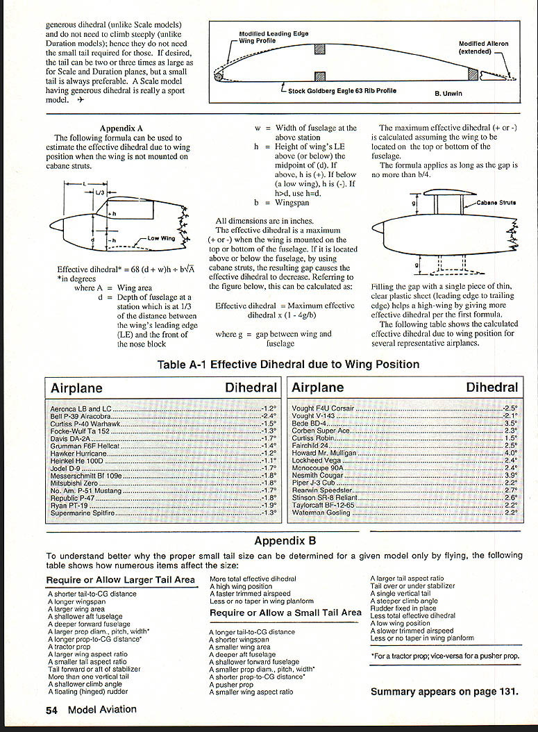
The following formula estimates the effective dihedral due to wing position when the wing is not mounted on cabane struts:
Effective dihedral* = 68 (d + w/h) ÷ b√A (in degrees)
where:
- A = Wing area (sq. in.)
- d = Depth of fuselage at a station located 1/3 of the distance between the wing leading edge (LE) and the front of the nose block (in.)
- w = Width of fuselage at the above station (in.)
- h = Height of the wing LE above (or below) the midpoint of d. If above, h is positive; if below (a low wing), h is negative. If h < d, use h = d.
- b = Wingspan (in.)
All dimensions in inches.
- The effective dihedral is maximum (positive or negative) when the wing is mounted on the top or bottom of the fuselage.
- If the wing is located above or below the fuselage using cabane struts, the resulting gap reduces the effective dihedral. The reduction can be calculated as:
Effective dihedral = Maximum effective dihedral × (1 - 4g/b)
where g = gap between wing and fuselage. This applies as long as the gap is no more than b/4.
- Filling the gap with a single piece of thin, clear plastic sheet (leading edge to trailing edge) helps a high-wing by increasing effective dihedral per the first formula.
The following table shows calculated effective dihedral due to wing position for several representative airplanes.
Table A-1 — Effective dihedral due to wing position
- Aeronca LB and LC — -1.2°
- Bell P-39 Airacobra — -2.4°
- Curtiss P-40 Warhawk — -1.5°
- Focke-Wulf Ta 152 — -1.3°
- Davis DA-2A — -1.1°
- Grumman F6F Hellcat — -1.4°
- Hawker Hurricane — -1.2°
- Heinkel He 100D — -1.7°
- Jodel D-9 — -1.8°
- Messerschmitt Bf 109e — -1.8°
- Mitsubishi Zero — -1.7°
- North American P-51 Mustang — -1.7°
- Republic P-47 — -1.8°
- Ryan PT-19 — -1.7°
- Supermarine Spitfire — -1.3°
- Vought F4U Corsair — -2.5°
- Vought V-143 — -1.2°
- Bede BD-4 — -2.3°
- Corben Super Ace — -2.5°
- Curtiss Robin — -2.3°
- Fairchild 24 — -2.0°
- Howard Mr. Mulligan — -2.4°
- Lockheed Vega — -2.5°
- Monocoupe 90A — -2.4°
- Nesmith Cougar — -2.0°
- Piper J-3 Cub — -2.3°
- Rearwin Speedster — -2.6°
- Stinson SR-8 Reliant — -2.6°
- Taylorcraft BF-12-65 — -2.6°
- Waterman Gosling — -2.2°
Appendix B
The following lists show how various items affect the required tail size.
Factors that require or allow a larger tail area
- A shorter tail-to-CG distance
- A longer wingspan
- A larger wing area
- A shallower aft fuselage
- A deeper forward fuselage
- A larger prop diameter, pitch, or width*
- A longer prop-to-CG distance*
- A tractor (front-mounted) prop
- A larger wing aspect ratio
- A smaller tail aspect ratio
- Tail located forward or aft of the stabilizer
- More than one vertical tail
- A shallow-cambered wing
- A floating (hinged) rudder
Factors that increase total effective dihedral
- A high wing position
- A faster trimmed airspeed
- Less or no taper in wing planform
Factors that require or allow a small tail area
- A longer tail-to-CG distance
- A shorter wingspan
- A smaller wing area
- A deeper aft fuselage
- A shallower forward fuselage
- A smaller prop diameter, pitch, or width*
- A shorter prop-to-CG distance*
- A pusher prop
- A smaller wing aspect ratio
Factors that allow a larger tail aspect ratio (or otherwise favor larger tail design)
- Tail over or under the stabilizer
- A single vertical tail
- A steeper climb angle
- Rudder fixed in place (non-hinged)
- Less total effective dihedral
- A low wing position
- A slower trimmed airspeed
- Less or no taper in wing planform
Note: The asterisks (*) indicate items related to propeller size/location that also affect tail sizing.
Summary appears on page 131.
Transcribed from original scans by AI. Minor OCR errors may remain.

