
Vickers Wellesley
Group Captain James Pelly-Fry
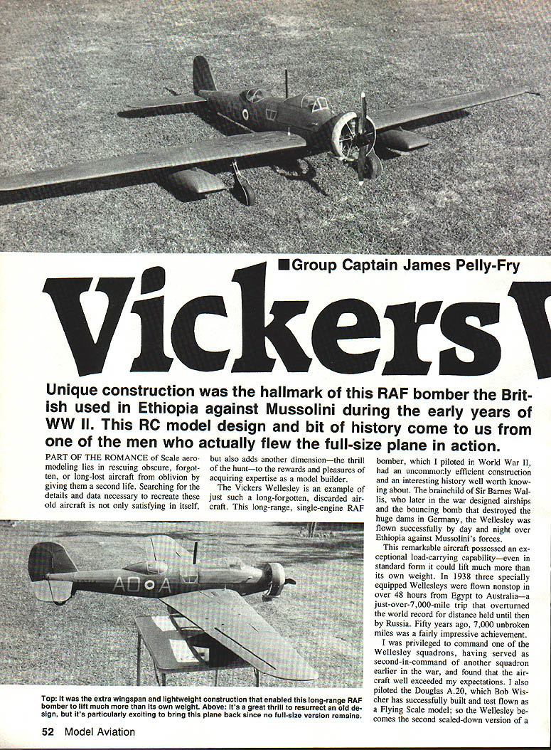
Unique construction was the hallmark of this RAF bomber the British used in Ethiopia against Mussolini during the early years of WWII. This RC model design and a bit of history come to us from one of the men who actually flew the full‑size plane in action.
Part of the romance of scale aero‑modelling lies in rescuing obscure, forgotten, or long‑lost aircraft from oblivion by giving them a second life. Searching for the details and data necessary to recreate these old aircraft is not only satisfying in itself, but also adds another dimension—the thrill of the hunt—to the rewards and pleasures of acquiring expertise as a model builder.
The Vickers Wellesley is an example of just such a long‑forgotten, discarded aircraft. This long‑range, single‑engine RAF bomber, which I piloted in World War II, had an uncommonly efficient construction and an interesting history well worth knowing about. The brainchild of Sir Barnes Wallis, who later in the war designed the bouncing bomb that destroyed the dams in Germany, the Wellesley was flown successfully by day and night over Ethiopia against Mussolini's forces.
This remarkable aircraft possessed an exceptional load‑carrying capability—even in standard form it could lift much more than its own weight. In 1938 three specially equipped Wellesleys were flown nonstop in over 48 hours from Egypt to Australia—a just‑over‑7,000‑mile trip that overturned the world record for distance held until then by Russia. Fifty years ago, 7,000 unbroken miles was a fairly impressive achievement.
I was privileged to command one of the Wellesley squadrons, having served as second‑in‑command of another squadron earlier in the war, and found that the aircraft well exceeded my expectations. I also piloted the Douglas A‑20, which Bob Wischer has successfully built and test‑flown as a flying scale model; so the Wellesley becomes the second scaled‑down version of a one‑time military prototype that I personally flew as an aviator. As full‑size aircraft, both the Douglas and the Wellesley did a superlative job in very different wartime circumstances, and both have an equal place in my sentiments.
The salient characteristics of the Wellesley are its very large wingspan (74 ft in the prototype), which is good news for a model version, and the use of a unique form of airframe construction that Barnes Wallis called geodetic, consisting essentially of a double‑spiral structure for the fuselage with a basket‑weave in the wing and stabilizer. This geodetic construction gave the Wellesley exceptional lightness and strength—the cardinal rule in airplane design. The wing in particular was both extremely light and very strong.
So far as we know, not a single Wellesley specimen has been recovered for posterity; all had been left to their desert fate after the Allied Forces moved into Southern Europe. Thus, in designing a scaled‑down version of this worthy aircraft, my research—the aforementioned hunt—would have to be limited to whatever drawings, sketches, and photographs I could obtain. Beaumont Aviation in London, which specializes in keeping records of aviation data from old magazines, books, etc., supplied some valuable material. A fortuitous coincidence also helped me: the Matchbox Model Company had recently produced a 12‑in. span "stick‑together" Wellesley kit, and it was the excellent material supplied by this cooperative manufacturer that got me started on the project.
Construction
Once sufficient data from which to work has been collected, the pivotal step in scale design is to decide upon a suitable scale and choose the hardware that determines all the rest—problems and all. For the Wellesley, after doing some figures on the back of an old envelope, I chose 1/10‑scale—as I had for the RAF Boston (my counterpart of the A.20). That way I'd get a big wing and keep the wing loading down to reasonable figures—the perennial aim that so often eludes the scale modeler. The wingspan would be 90 in., and I hoped to get the weight down to around eight pounds.
For power, the Enya .40‑4C four‑stroke seemed promising. I'd successfully fitted a pair of them to the A.20; I also happened to have one of these engines to spare from my friend Bud Voss. My only uncertainty concerned whether the Enya had sufficient power to get the big Wellesley airborne. The landing gear—a tail‑down retractable job—was a further consideration, and I decided to stay with proven production practice. In the event the Enya proved equal to the task.
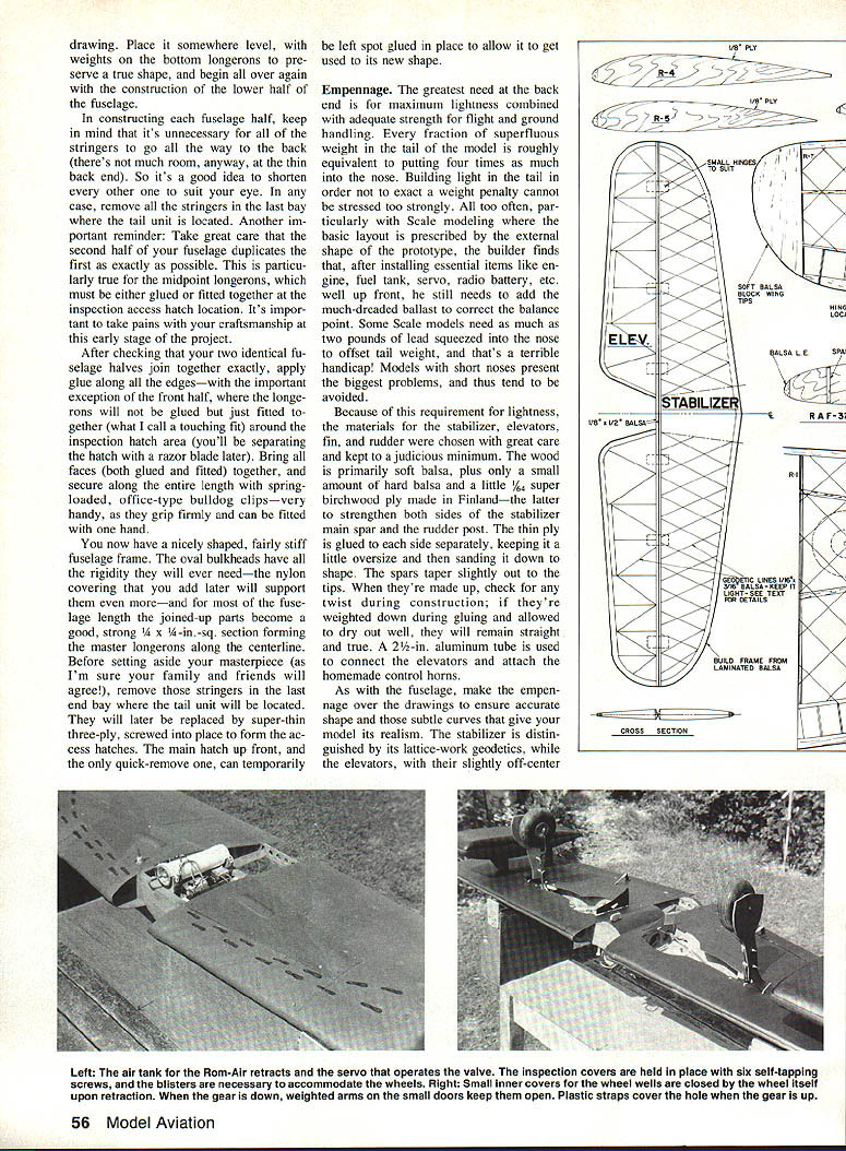
The landing gear I used was the proven Rom‑Air type. As in the Boston (where it gives creditable service even when high wing loading sometimes occasions dramatic arrivals on touchdown), it seemed a natural choice.
Fuselage
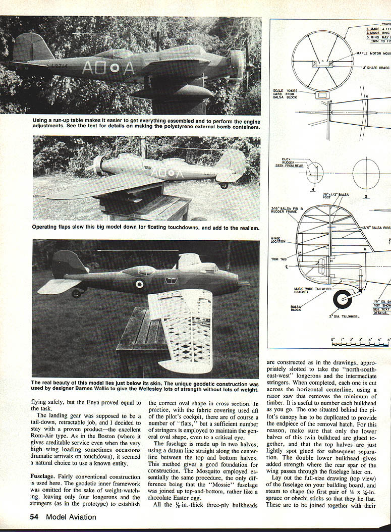
Fairly conventional construction is used here. The geodetic inner framework was omitted to save weight, leaving only four longerons and the stringers (as in the prototype) to establish the correct oval cross section. With fabric covering used aft of the pilot's cockpit, there are a number of flats, but a sufficient number of stringers is employed to maintain the general oval shape to a critical eye.
The fuselage is made up in two halves, using a datum line along the centreline between the top and bottom halves. This method gives a good foundation for construction; the Mosquito employed essentially the same procedure, the only difference being that the Mosquito fuselage was joined top‑and‑bottom, rather like a chocolate Easter egg.
All the 1/8‑in.‑thick three‑ply bulkheads are constructed as in the drawings, appropriately slotted to take the north‑south‑east‑west longerons and the intermediate stringers. When completed, each bulkhead is cut across the horizontal centreline using a razor saw that removes the minimum of timber. Number each bulkhead as you go. The one situated behind the pilot's canopy must be cut out to provide the endpiece of the removal hatch; make sure that only the lower halves of this twin bulkhead are glued together, and that the top halves are just lightly spot‑glued for subsequent separation. The double lower bulkhead gives added strength where the rear spar of the wing passes through the fuselage later on.
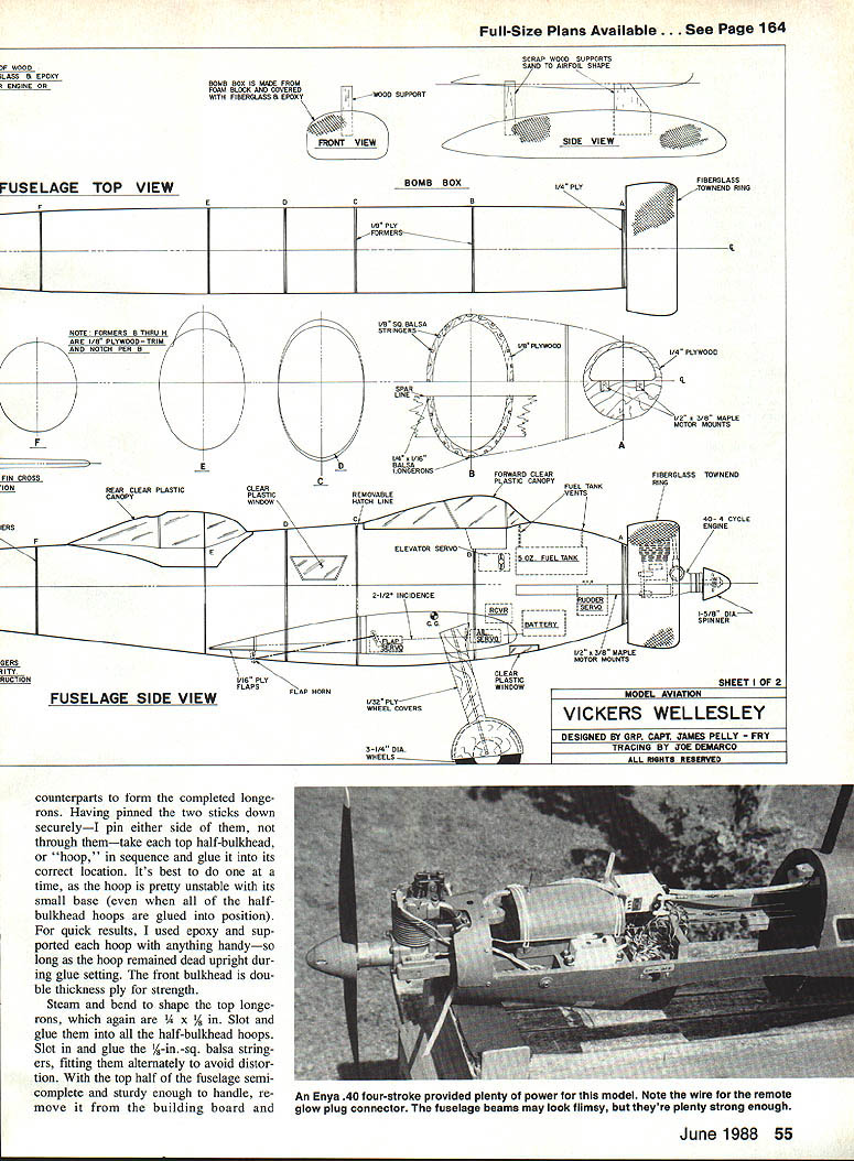
Lay out the full‑size drawing (top view) of the fuselage on your building board and steam‑shape the first pair of 1/4 x 1/8‑in. spruce or obeche sticks so that they lie flat. These are to be joined together to form the completed longerons. Having pinned the two sticks down securely (I pin either side of them, not through them), take each top half bulkhead, or "hoop," in sequence and glue it into its correct location—one at a time, as the hoop is unstable with its small base. For quick results I used epoxy and supported each hoop so that it remained dead upright during glue setting. The front bulkhead is double‑thickness ply for strength.
Steam and bend to shape the top longerons (1/4 x 1/8). Slot and glue them into all the half bulkhead hoops. Slot in and glue 1/8‑in.‑sq. balsa stringers, fitting them alternately to avoid distortion. With the top half semi‑complete and sturdy enough to handle, remove it from the building board and fit the bottom half around the ply formers. Glue the bottom longerons and stringers in position, taking care to avoid any twist—misalignment here will be difficult to correct later.
The cockpit beams are laminated from 1/8‑in. ply and 1/8‑in. balsa and glued into slots in the longerons. The false bomb bay is formed from balsa and ply and glued into position. The undercarriage legs are 1/8‑in. music wire bent to shape and secured at the ply motor mounts. Wheels are 3‑1/4 in. diameter and are fitted with 1/8‑in. ply wheel covers as shown on the plans.
The tail unit is built up on the plan in conventional fashion, with the fin and rudder sheeted in 1/16‑in. ply and the tailplanes in 1/16‑in. balsa. Control horns and hinges are fitted before final covering to avoid access problems later.
After checking that your two identical fuselage halves join together exactly, apply glue along all the edges—with the important exception of the front hatch area, where the longerons will not be glued but just fitted together (a touching fit) to allow later removal. Bring all faces together and secure along the entire length with spring‑loaded bulldog clips.
You now have a nicely shaped, fairly stiff fuselage frame. The oval bulkheads have all the rigidity they will need; the covering added later will support them even more. For most of the fuselage length the joined parts become a good, strong 1/4 x 1/4‑in. sq. section forming the master longerons along the centreline. Remove the stringers in the last bay where the tail unit is located; these will be replaced later by super‑thin three‑ply screwed into place to form access hatches. The main hatch up front, and the only quick‑remove one, can be temporarily left spot‑glued to allow it to get used to its new shape.
Covering was accomplished with lightweight silkspan doped with nitrate dope and finished with two coats of sanding sealer and three coats of model aircraft enamel. Decals were home‑made from photocopies sealed with clear dope. Balance the model with the fuel tank empty; the centre‑of‑gravity is shown on the plan and should be checked before the first flight.
Power for the model was provided by an Enya .40 four‑stroke, which proved amply powerful for safe takeoff and climb. The engine was mounted on 3/16‑ and 3/8‑in. maple motor mounts laminated to the firewall. A remote glow‑plug connector was fitted for convenience.
Radio installation consists of elevator, rudder and throttle servos mounted on ply platforms, with the receiver and battery tucked beneath the cockpit decking. Pushrods are 1/16‑in. music wire with bellcranks as shown on the plan. The retractable main undercarriage was not used on the model; instead a simple fixed gear with streamlined fairings gives a reliable and robust installation while keeping construction straightforward.
Flying trim called for 1/4 in. up elevator and 3/16 in. right rudder at neutral; these settings were arrived at after a few gentle test flights. The Wellesley model is a delight to fly—its large wing area and light wing loading make it a steady, forgiving machine ideal for scale‑like, long‑duration flights.
Canopies, Hatch and Cockpit
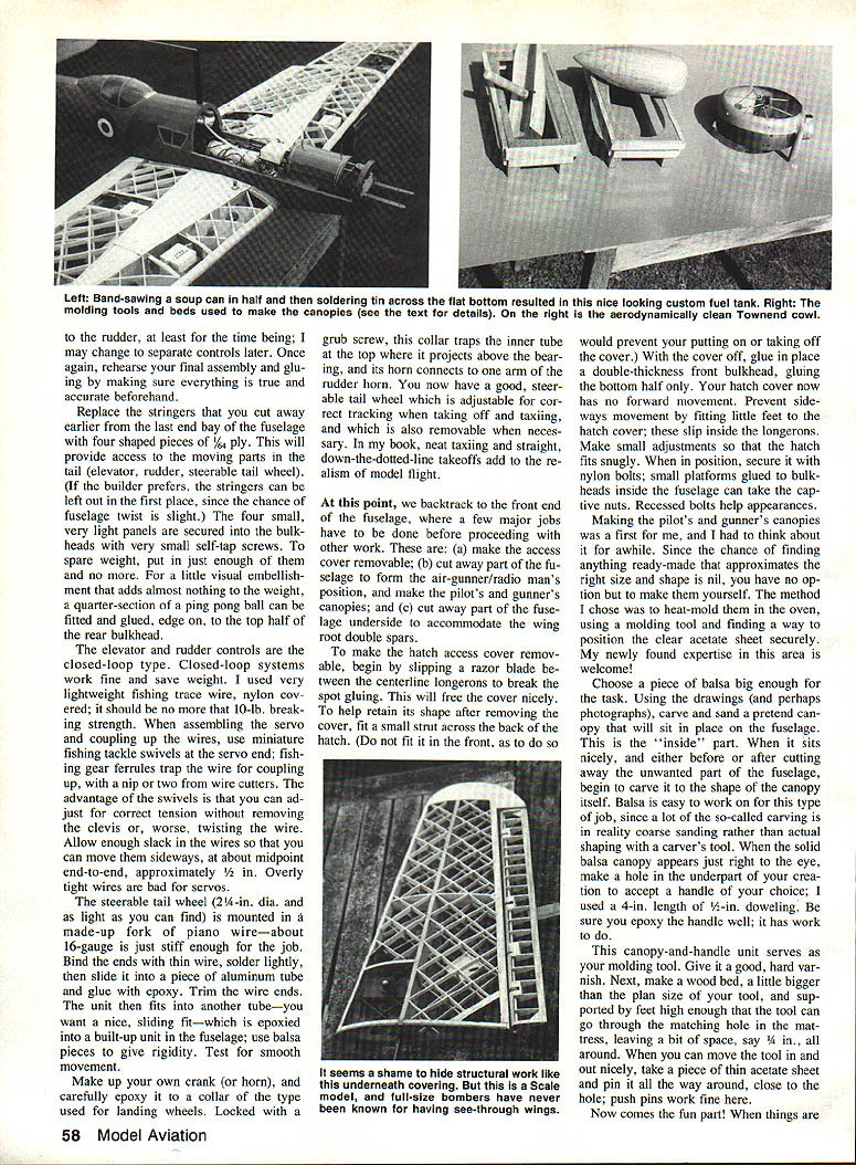
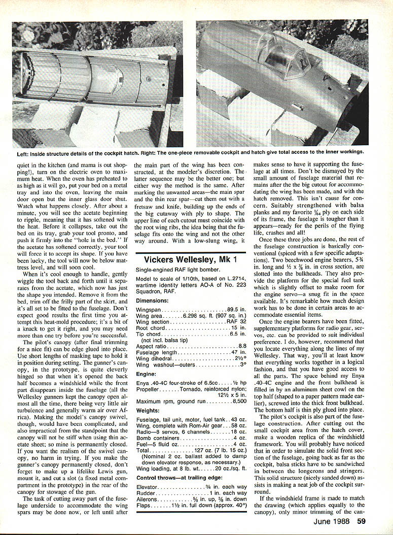
To make the hatch access cover removable, slip a razor blade between the centreline longerons to break the spot gluing. This will free the cover. To help retain its shape after removing the cover, fit a small strut across the back of the hatch (do not fit it in the front, as that would prevent removal). With the cover off, glue in place a double‑thickness front bulkhead, gluing the bottom half only so the hatch has no forward movement. Prevent sideways movement by fitting little feet to the hatch cover that slip inside the longerons. Secure with nylon bolts and captive nuts on small internal platforms; recessed bolts improve appearance.
Making the pilot's and gunner's canopies was a first for me; the method I used was heat‑moulding thin acetate over a carved balsa tooling shape. The process: carve and sand a balsa tool to the canopy shape, varnish it, position a thin acetate sheet over a bed with a hole, heat the acetate in an oven until pliable, and press the tool into it. When cooled, trim and fit. The pilot's canopy can be edge‑glued into place and held with masking tape while setting. The gunner's canopy in the prototype was hinged cleverly, but making a working swivel on the model is impractical with thin acetate, so mine is permanently closed. If you make it fixed, consider adding a lifelike Lewis gun and a slot for the stowage compartment as in the prototype.
Cutting away part of the fuselage underside to accommodate the wing root double spars may be done now or after the main wing is constructed. Mark the unwanted areas (main spar and rear spar) and cut them out with a fretsaw and knife, building up the ends of the cutaway with ply to shape. The upper line of each cutout must coincide with the root wing ribs so the fuselage fits onto the wing, not the other way around. Reinforce the remaining edges with balsa planks and 1/64‑in. ply as necessary.
Two beechwood engine bearers (5/16 in. long and 1/2 x 3/8 in. cross section) are slotted into the bulkheads. They provide the platform for the fuel tank, slightly offset to make room for the engine servo. Supplementary platforms for radio gear and servos are fitted to suit individual layout. The space behind the Enya .40‑4C and the front bulkhead is filled by an aluminium sheet cowl on the top half, shaped to a paper pattern and screwed into the thick front bulkhead; the bottom half is ply glued into place.
The pilot's cockpit surround is built up with balsa slats sandwiched between longerons and stringers to simulate the solid front section of the fuselage. If the windshield frame is made to match the drawing, only minor trimming of the canopy will be necessary when fitting. CA glue secures the screen into the frame and small pins at the base hold it firmly. The forward hatch is detachable to allow access to the receiver and servos.
The undercarriage on the full‑size Wellesley is fixed and provided with spats. The model undercarriage can be a simple job: substantial 5/32‑in. dia. sprung legs braced with piano wire V‑struts, wheels around 3‑1/8 in. diameter, faired with balsa spats for appearance.
Empennage
The greatest need at the back end is for maximum lightness combined with adequate strength for flight and ground handling. Every fraction of superfluous weight in the tail of the model is roughly equivalent to putting four times as much into the nose. Building light in the tail to avoid a weight penalty cannot be overemphasized.
Materials for the stabilizer, elevators, fin, and rudder were chosen with care and kept to a minimum. The wood is primarily soft balsa, with a small amount of hard balsa and a little 1/8‑in. birch ply (used to strengthen both sides of the stabilizer main spar and the rudder post). Thin ply is glued to each side separately, kept slightly oversize and sanded to shape. The spars taper slightly out to the tips. Check for twist during construction and allow glue to dry with the surfaces weighted down so they remain straight.
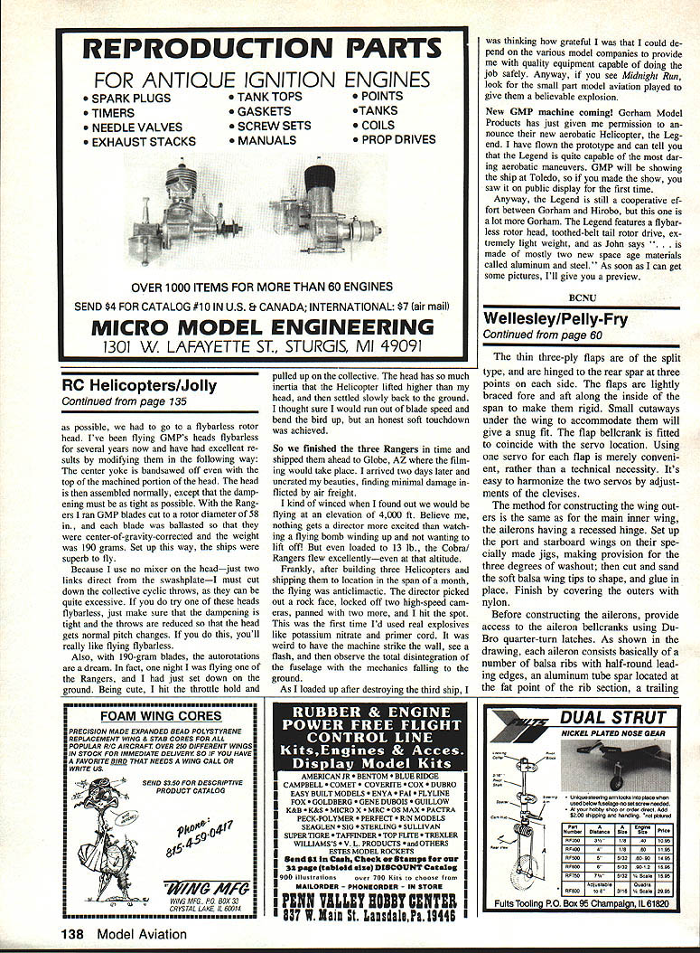
A 2‑1/2‑in. aluminium tube is used to connect the elevators and attach a homemade control horn. Build the empennage over the drawings to ensure accurate shape and realistic curves. The stabilizer is distinguished by its lattice‑work geodetics, while the elevators are conventional except for their thinness. Keep hinge lines close to the rib webs to minimize torsional flexing. Cover the tail surfaces with a lightweight iron‑on film and be sparing with dope; the lighter the better.
The method to fit the stabilizer and elevators into the fuselage is to cut away the leading edge spar sufficiently to enable the unit to be maneuvered into place. Stand the fuselage on its nose, steady it, and glue the main spar onto the back of the rearmost bulkhead at the midpoint. Ensure the stabilizer is dead square to the fuselage when upright. Build up the "broken" leading edge with a short piece of hard balsa and glue to the bulkhead alongside, using a filler piece if necessary.
The fin‑rudder assembly, completed but not necessarily covered at this stage, is then set up in the fuselage. Make provision at the foot of the spar (the rudder post) for the spar to be standing and glued onto a small block; the rudder must move freely and the double arms or horns must have full travel. The Wellesley does not need much rudder in normal flight, since the ailerons do much of the work. In my model the ailerons are coupled to the rudder so that little differential trim is necessary; you may prefer separate controls.
Replace the stringers that you cut away earlier from the last end bay with four shaped pieces of 1/4‑ply to provide access to the moving parts in the tail (elevator, rudder, steerable tailwheel). The four small panels are secured to the bulkheads with very small self‑tapping screws. For a light visual detail, a quarter‑section of a ping‑pong ball can be fitted and glued, edge on, to the top half of the rear bulkhead.
The elevator and rudder controls are the closed‑loop type. Closed‑loop systems work fine and save weight. I used very lightweight fishing trace wire, nylon covered, with about 10‑lb breaking strength. Use miniature fishing swivels at the servo end and ferrules to trap the wire, with a nip or two from wire cutters. Allow enough slack in the wires so you can move them sideways about 1/2 in. at the midpoint end‑to‑end. Overly tight wires are bad for servos.
The steerable tail wheel (2‑1/4‑in. dia., as light as possible) is mounted in a made‑up fork of piano wire (about 16‑gauge). Bind the ends with thin wire, solder lightly, then slide into a piece of aluminium tube and glue with epoxy. The unit then fits into another tube epoxied into a built‑up unit in the fuselage; use balsa pieces for rigidity. Make up a crank (or horn) and epoxy it to a collar similar to those used for landing wheels. Locked with a grub screw, this collar traps the inner tube at the top where it projects above the bearing, and its horn connects to one arm of the rudder horn. This gives a good, steerable tail wheel adjustable for correct tracking.
Wing
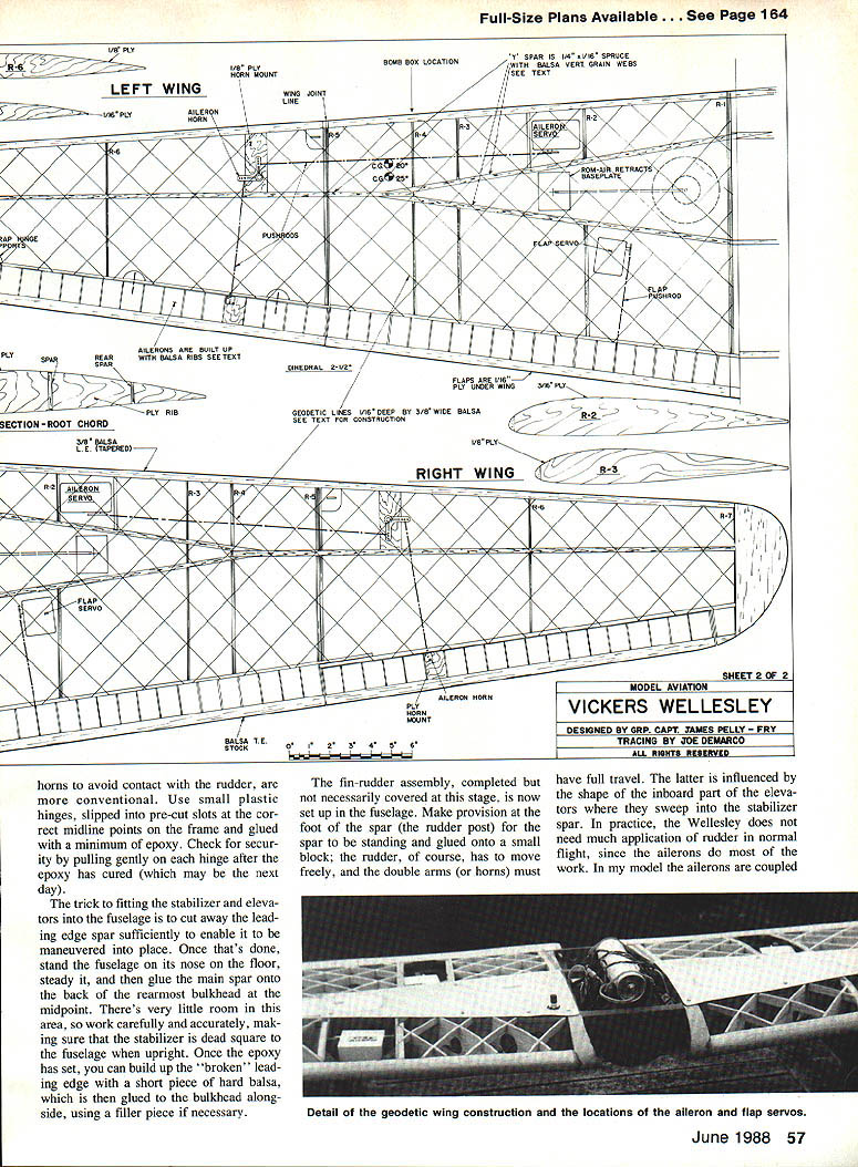
In the Wellesley, constructing the wing is the key step. My priority was to suggest as near as possible the geodetic construction of the prototype while keeping the model practical. I used removable outer wings as in the Boston. The fuselage sits on the wing and is held by four bolts; I mounted the aileron and flap servos and the Rom‑Air unit on the wing, with the rest of the radio gear in the fuselage. This simplifies assembly and maintenance.
As in the prototype, the starting point is the Y‑shaped main spar. This gives great strength and accommodates the landing gear. The spar is fashioned of top and bottom sticks of 1/4 x 1/4 spruce, supplemented with vertical grain balsa webs and ply facing near the wing roots. The spars are very sturdy before assembly.
The wing structure begins with four master ply ribs distributed along the main wing assembly as shown on the drawings. Cut small, narrow vertical slots in the outboard master ribs for the wing joiners (refer to the plans). Port and starboard wings are constructed separately, with the spruce spars projecting beyond the wing root ribs to form the centre section.
Place the wing skeleton on the plan drawing, add the balsa shaped leading edge spar, then the rear spar built up from 1/8‑in. strip balsa with 1/8‑in. ply facings. Glue each ply face separately, sand to shape, and you will have a light, stiff spar.
Install balsa platforms for the flap and aileron servos according to the drawing. All access panels (thin ply) can be screwed with small self‑tapping screws into small hardwood blocks.
Next comes the geodetic look. Prepare many balsa sticks from 3/16‑in. soft sheet balsa, about 3/32 in. wide. Fit sticks in a herringbone pattern across the upper part of each half‑wing, then run the pattern in the opposite direction so they slot together, creating diamond shapes. Position the sticks slightly higher than the wing contour.
Make a sanding stick (a straight batten about 1/2 in. x 1/4 in. x 1 1/4 in.) covered with sandpaper. With the half‑wing on your lap, sand evenly across the span to the structure, working with the grain. When close to the master ribs, finish with fine sandpaper. Repeat on the underside. The result is a nicely shaped, accurate tapered wing of geodetic construction—twist‑free and light.
Make jigs to support the wings with the required 2½° dihedral and ensure identical rib angles fore and aft. Connect the projecting spruce spars that form the centre section with spruce spar splices (epoxy works well). Beef up the spar assembly with vertical grain balsa where the join occurs and add three‑ply faces to each spar; these also provide locations for the brackets that accept the nylon bolts which attach the fuselage to the wing.
Trial fit the fuselage in the wing, making adjustments so the wing root ribs sit neatly into the fuselage cutout. The wing must be dead square with the fuselage centreline.
The thin three‑ply flaps are split type, hinged to the rear spar at three pivots on each side and lightly braced fore and aft to make them rigid. The flap bellcrank is fitted to coincide with the servo location. Using one servo for each flap is convenient; harmonize them by adjusting the clevises.
The outer panels are constructed the same way as the centre section, with recessed hinges for the ailerons. Set up port and starboard outers on jigs, providing the correct washout (3° on the outer panels), then cut and sand the soft balsa wing tips to shape and glue in place. Finish by covering the outers with nylon.
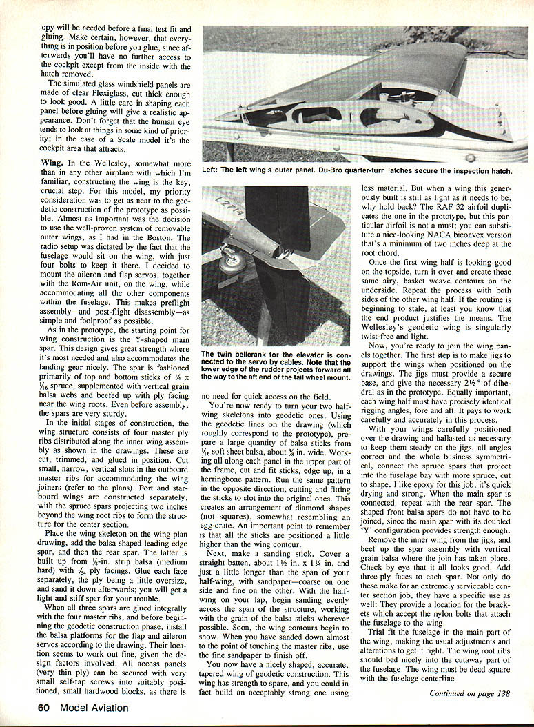
Before constructing the ailerons, provide access to the aileron bellcranks using Du‑Bro quarter‑turn latches. Each aileron consists of balsa ribs with half‑round leading edges, an aluminium tube spar at the fat point of the rib, a sheet balsa trailing edge and a hardwood trailing lug. I hinged the ailerons with nylon tape and glued them to the wing. Make servo connections and check free travel. Balance the wing by adding weight to the nose if necessary.
Geodetic appearance on the fuselage and wing is suggested by installing diagonal stringers over sheeted surfaces where scale effect is desirable. These are light strip balsa glued over the sheeted surfaces and sanded down to give the impression of the original latticework without the complication of true geodetic construction.
Tankage and plumbing should be attended to early so the centre of gravity can be checked as the fuselage goes together. On this model the tank is placed slightly to starboard of centre to leave room for the servo bay and throttle linkage. Balance fore and aft by moving the receiver and battery pack within the fuselage and by adding ballast if necessary.
Rigging of controls is conventional, using pushrods for the ailerons and elevator and a pull‑pull cable system for the rudder. Ensure all control runs are free from binding and that servo throws are set to the recommended figures. Final trimming is best done with small increments of elevator and rudder, and with the flaps used to aid landing approach.
Covering is with lightweight tissue doped taut for a period appearance while keeping weight down. Markings and finish follow wartime photographs and the identity letters shown on the drawings.
Flying the scaled‑down Wellesley is rewarding. With weight near the target and the Enya .40 giving a healthy turn of propeller, takeoffs are brisk and climb steady. The model is stable and forgiving, reflecting the full‑size aircraft's benign flying characteristics. Approach speeds are moderate, and with flaps set the landing runs are manageable. Trim carefully and enjoy resurrecting this attractive and historic design in miniature.
Specifications
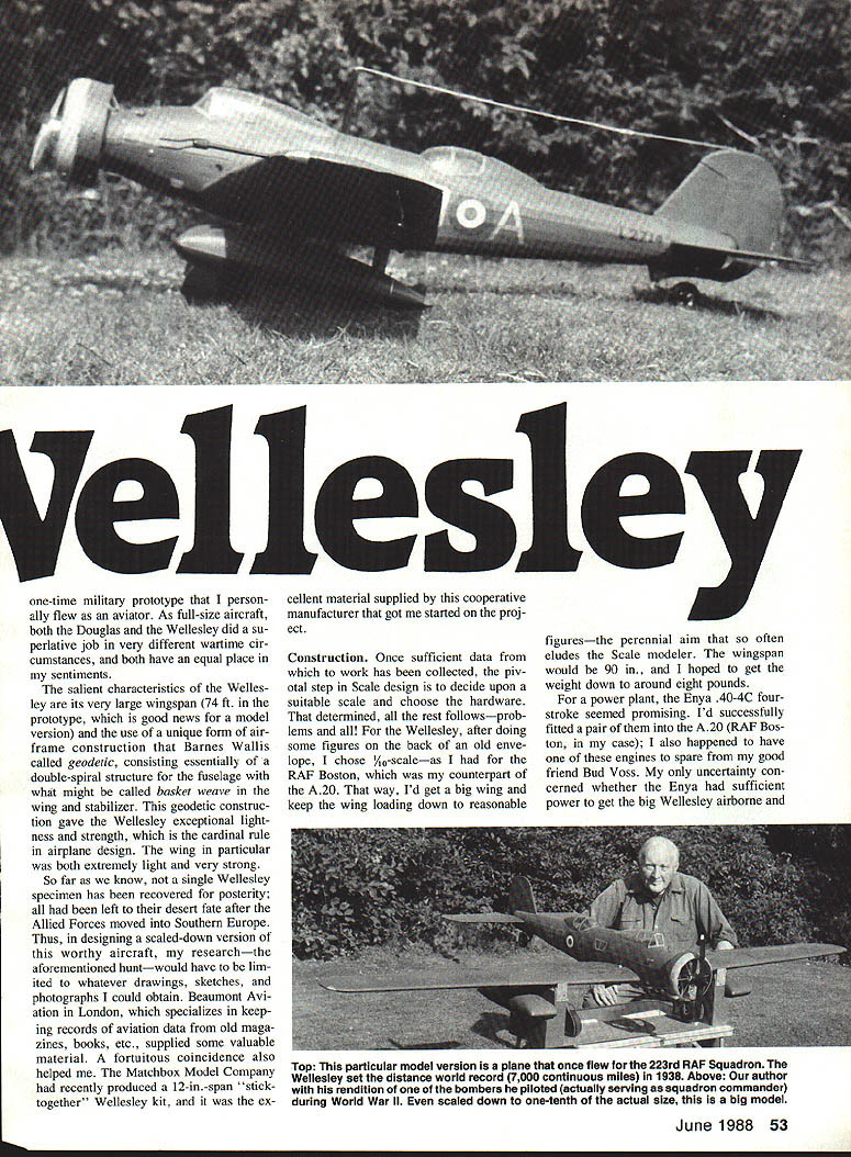
Vickers Wellesley, Mk I — Single‑engined RAF light bomber Model to scale 1/10, based on L.2714, wartime identity letters AO‑A of No. 223 Squadron, RAF
- Wingspan: 89.5 in.
- Wing area: 6,298 sq. ft. (907 sq. m.) [as printed on the plans]
- Wing section: RAF 32
- Root chord: 15 in.
- Tip chord: 6.5 in. (not incl. balsa tip)
- Aspect ratio: 8.8
- Fuselage length: 47 in.
- Wing dihedral: 2½°
- Wing washout—outers: 3°
Engine:
- Enya .40‑4C four‑stroke (6.5 cc) — approx. 1.2 h.p.
- Propeller: Tornado reinforced nylon, 12½ x 5 in.
- Maximum rpm (ground run): 8,500
Weights:
- Fuselage, tail unit, motor, fuel tank: 43 oz.
- Wing, complete with Rom‑Air gear: 58 oz.
- Radio—8 servos, 6 channels: 18 oz.
- Bomb containers: 4 oz.
- Fuel—5 fl. oz.: 4 oz.
- Total: 127 oz. (7 lb. 15 oz.)
- Nominal 2 oz. ballast added to damp down elevator response as necessary.
- Wing loading (at 8 lb. weight): 20 oz./sq. ft.
Control throws (at trailing edge):
- Elevator: 3/8 in. each way
- Rudder: 1 in. each way
- Ailerons: 5/8 in. up, 3/8 in. down
- Flaps: 1½ in. full down (approx. 40°)
Notes on Finish and Flight
- Covering: lightweight tissue doped taut (or lightweight iron‑on film for tail surfaces). Be sparing with dope to keep weight down.
- Markings: follow wartime photographs and drawings for authentic identity letters and finish.
- Preflight checks: ensure all control runs are free, servos set to recommended throws, C of G checked with fuel tank empty.
- Trim: small increments of elevator and rudder; use aileron‑to‑rudder coupling or separate controls as preferred. Flaps help on final approach.
Transcribed from original scans by AI. Minor OCR errors may remain.

