
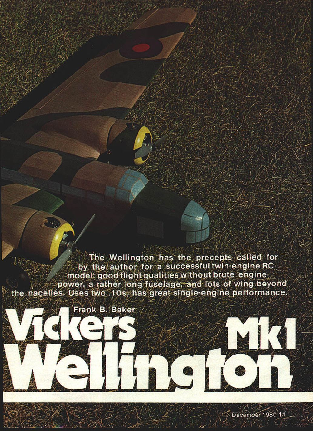
Vickers Wellington Mk1
Overview
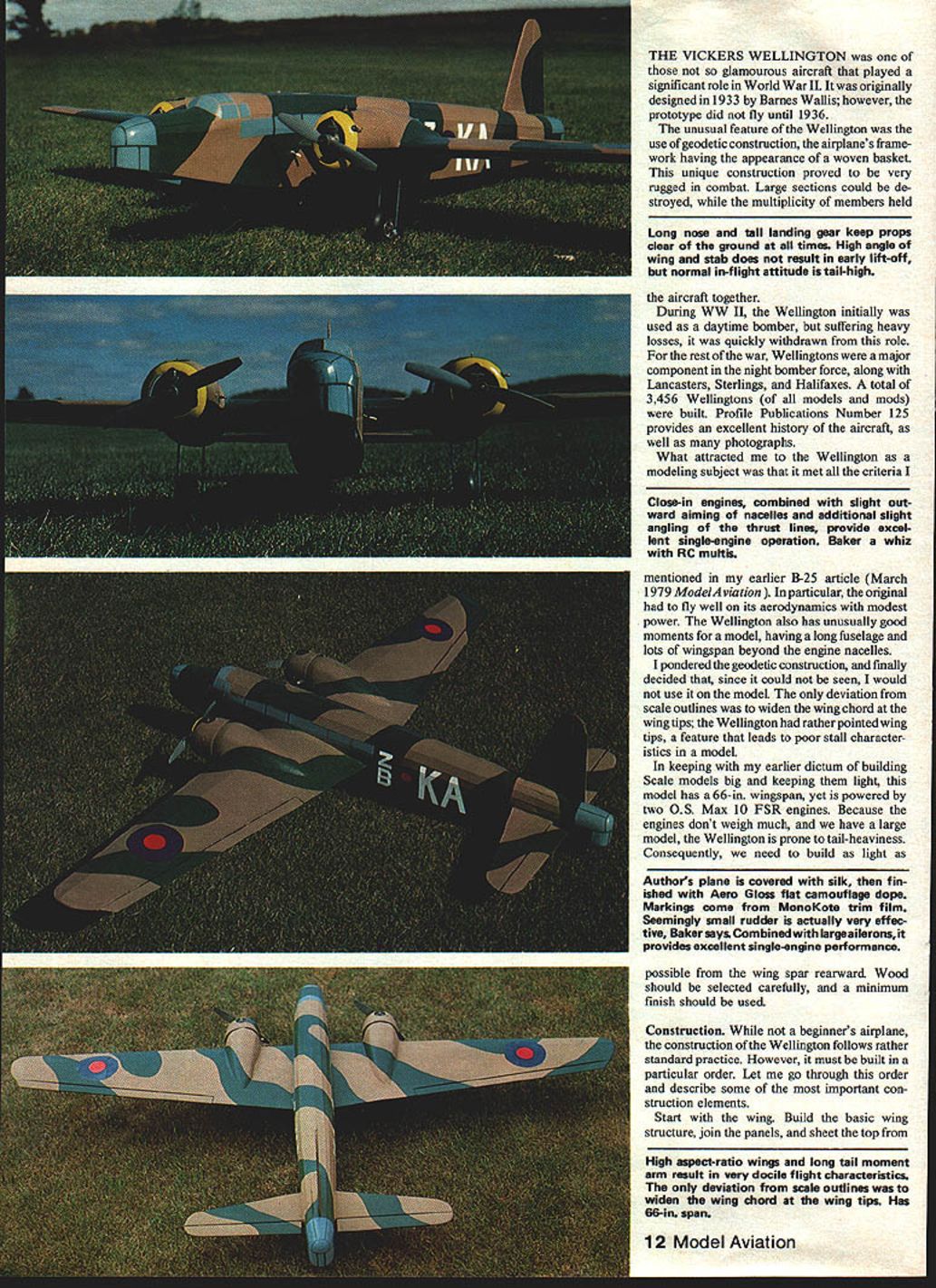
The Vickers Wellington was one of those not-so-glamorous aircraft that played a significant role in World War II. Originally designed in 1933 by Barnes Wallis, the prototype did not fly until 1936. Its most unusual feature was the use of geodetic construction — the airplane's framework had the appearance of a woven basket. This unique construction proved very rugged in combat: large sections could be destroyed while the multiplicity of members held the aircraft together.
During WWII the Wellington was initially used as a daytime bomber but, suffering heavy losses, it was quickly withdrawn from that role. For the rest of the war Wellingtons were a major component of the night-bomber force, along with Lancasters, Sterlings, and Halifaxes. A total of 3,456 Wellingtons (all models and mods) were built. Profile Publications No. 125 provides an excellent history of the aircraft and many photographs.
What attracted me to the Wellington as a modeling subject was that it met the criteria I outlined in my earlier B-25 article (Model Aviation, March 1979). In particular, the original flew well aerodynamically with modest power. The Wellington also has unusually favorable moments for a model, having a long fuselage and lots of wingspan beyond the engine nacelles.
I considered modeling the geodetic construction, but since it would not be visible I omitted it. The only deviation from scale outlines was to widen the wing chord at the tips; the prototype had rather pointed tips, a feature that leads to poor stall characteristics in a model.
In keeping with my earlier dictum of building scale models big and light, this model has a 66-in. wingspan yet is powered by two O.S. Max 10 FSR engines. Because the engines are light and the model is large, the Wellington is prone to tail-heaviness. Therefore build as light as possible from the wing spar rearward: select wood carefully and use a minimum finish.
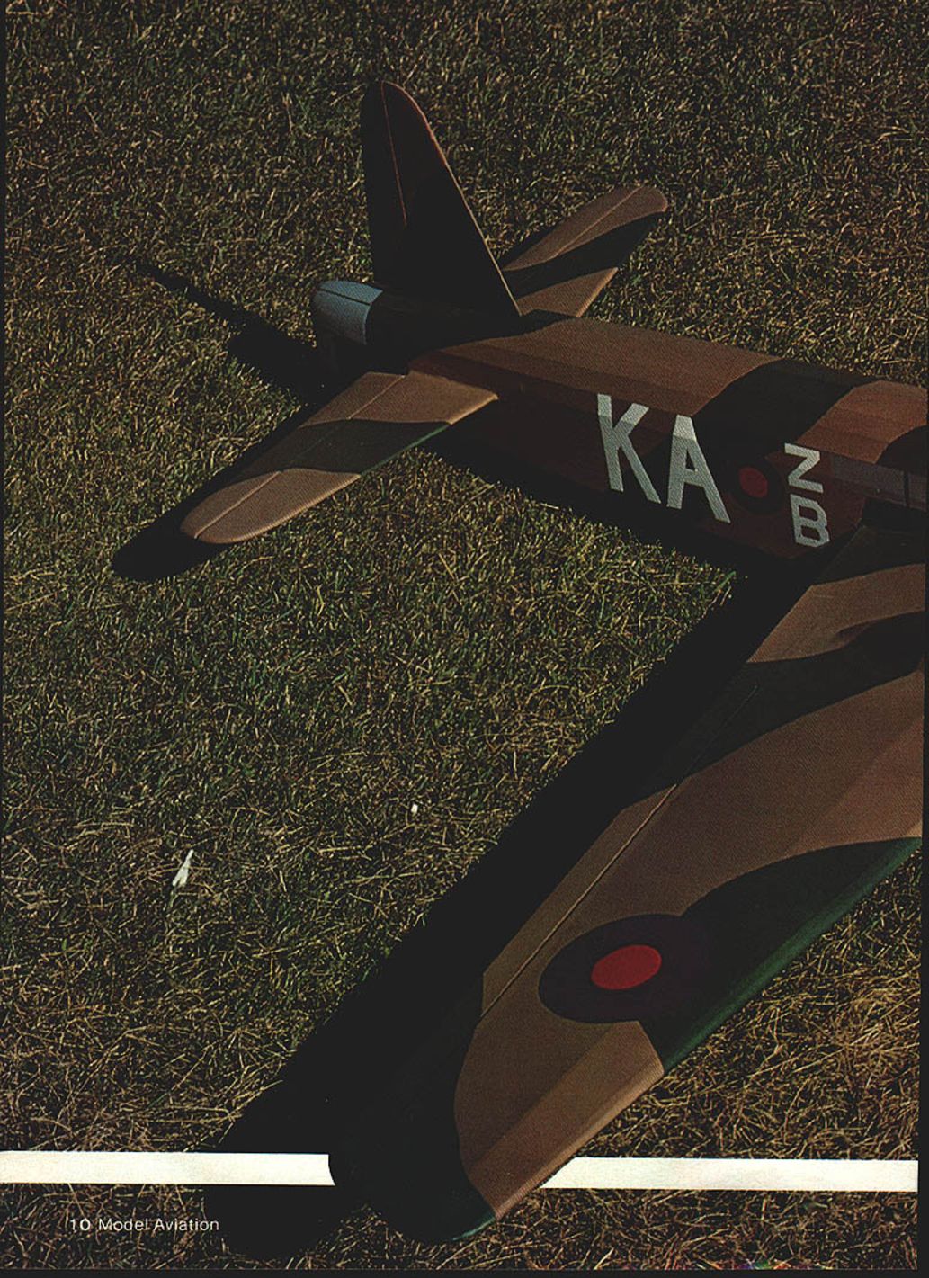
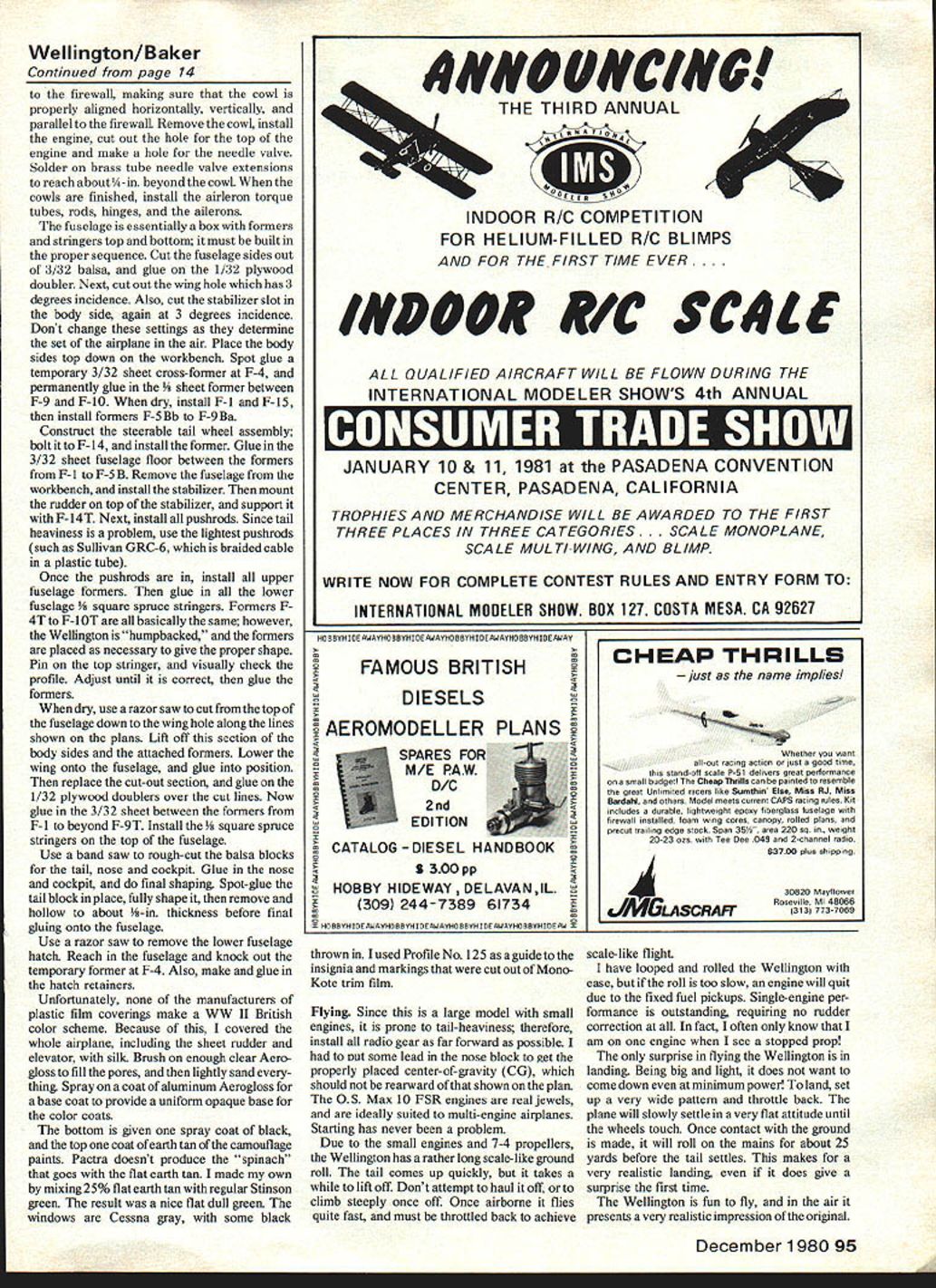
My plane is covered with silk and finished with Aerogloss flat camouflage dope. Markings come from MonoKote trim film. The seemingly small rudder is actually very effective; combined with large ailerons it provides excellent single-engine performance.
Design features
- High aspect-ratio wings and a long tail moment arm result in very docile flight characteristics.
- Wing chord widened at the tips (deviation from scale) to improve stall behavior.
- Good single-engine performance; model often requires no rudder correction when one engine quits.
Parts and materials (from plans and notes)
- Splice plate
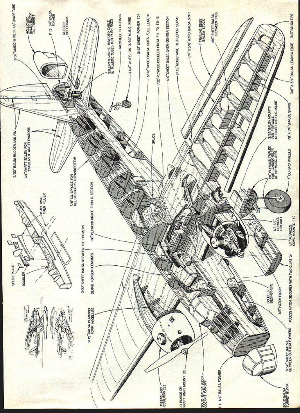
- 5/32" balsa rudder and fin
- 1/4" sheet balsa stabilizer and elevators
- 1/8" sq. spruce for all stringers top and bottom
- 3/32" sheet balsa between top formers
- 3/32" balsa planking for nacelles
- Servo for both engines
- 3/32" sheet balsa between bottom formers
- 1/4" plywood cowl mounts
- Engine mounted on solid balsa block
- Solid balsa block cockpit canopy
- 1/4" balsa formers
- Turret block (hollowed)
- 3/32" plywood floor
- Access hatch secured with two clips
- Doubler begins here (as shown on plans)
- 1/8" plywood tripled for landing gear
- 1/4" x 3/8" hard balsa spar
- 3/32" music wire to aileron servo
- 3/32" sheet balsa over center section
- 1/8" plywood doubler over center section
- 3/8" x 3/16" balsa leading edge
- 3/8" x 1/4" balsa tips
- 1/8" x 1/4" spruce spars
- 1/8" plywood mounts for wheels
- 3" dia. Du-Bro wheels
- 3/32" music wire in 1/8" brass tube
- 1/4" x 3/8" balsa leading edge (wing tips)
- 1/16" sheet balsa between ribs
- 1/8" ply doubler at top former (F3)
- 1/8" ply braces through C section
- 1/8" sq. spruce mounts for firewall
- 1/8" balsa block tail turret (hollowed)
- Bellcrank
- Braided cable in plastic tubes for pushrods
- Tailwheel bellcrank
- 1-1/4" wheel on 3/32" music wire
- Splice plate doubler
- Note: spruce spars flush with top sheeting. Cut out rib 1; install servo mounting plate.
Construction
#### Wing
- Start with the wing. Build the basic wing structure, join the panels, and sheet the top sheeting.
- Cut out rib 1 and install the servo mounting plate. Using low-profile servo mounting tape, install the motor-control servo.
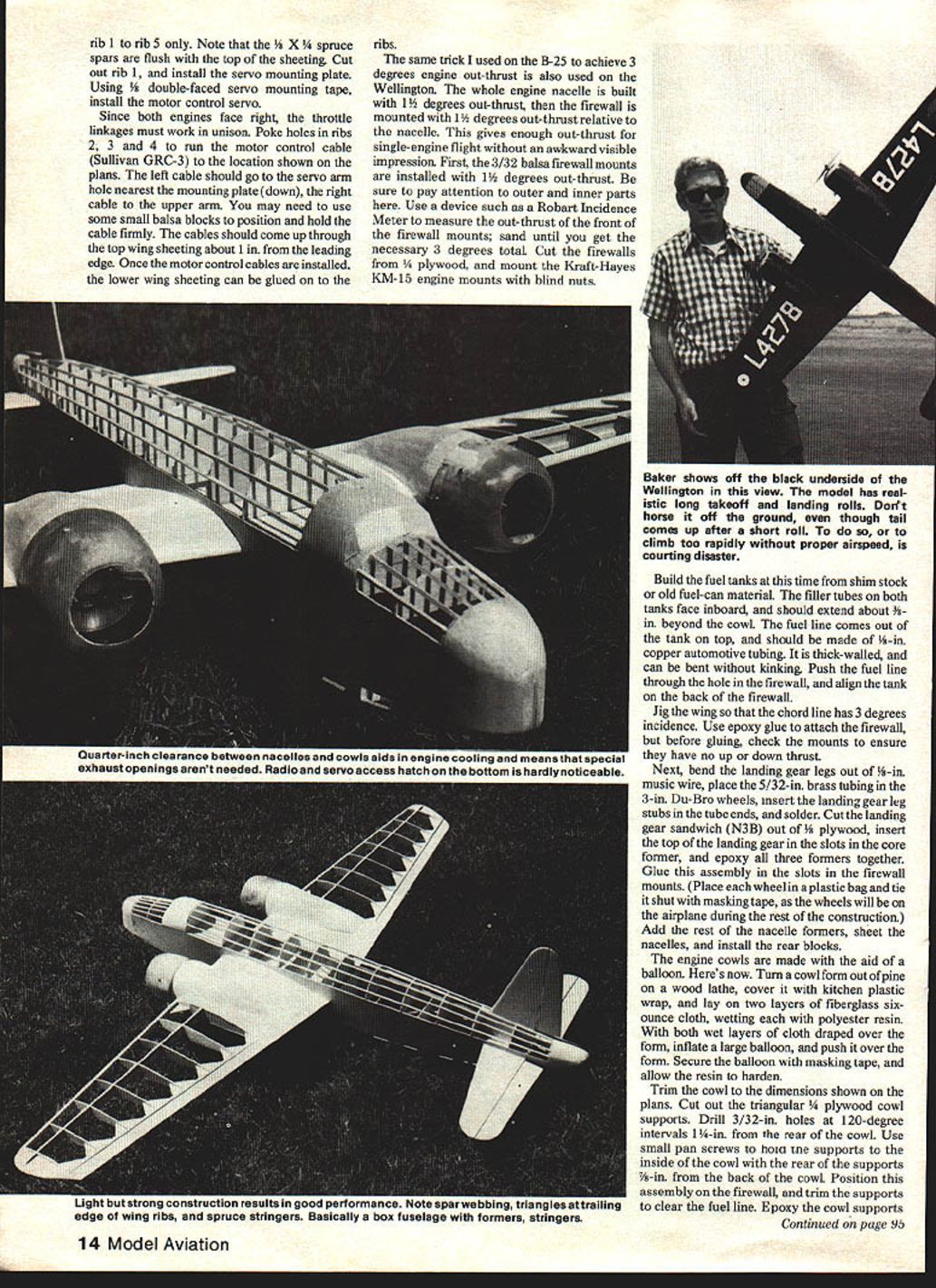
- Since both engines face to the right, throttle linkages must work in unison. Poke holes in ribs 2, 3, and 4; run the motor control cables. The left cable should lead to the lower servo-arm hole (nearest the mounting plate), and the right cable to the upper arm. Use small balsa blocks as needed to position and hold the cables firmly.
- The cables should come up through the top wing sheeting about 1 in. from the leading edge. Once the motor control cables are installed, glue on the lower wing sheeting to the ribs.
Engine thrust setup:
- Use the same technique I used on the B-25 to achieve 3° total out-thrust: build the nacelle with 1-1/2° out-thrust, then mount the firewall with an additional 1-1/2° out-thrust relative to the nacelle. This yields the required 3° total out-thrust without an awkward visible impression.
- Install 3/32" balsa firewall mounts with 1-1/2° out-thrust. Use a device such as a Robart incidence meter to measure and sand the mounts until you obtain the necessary total of 3°.
- Cut the firewalls from 1/8" plywood and mount the Kraft-Hayes KM-15 engine mounts with blind nuts.
Fuel tanks:
- Build fuel tanks from shim stock or old fuel-can material. The filler tubes on both tanks face inboard and should extend about 3/8" beyond the cowl.
- The fuel line exits the tank on top and should be made of 3/16" copper automotive tubing (thick-walled and bendable without kinking). Push the fuel line through the firewall hole and align the tank on the back of the firewall.
Jigging:
- Jig the wing so the chord line has 3° incidence.
- Use epoxy to attach the firewall, but before gluing, check the mounts to ensure there is no unintended up or down thrust.
#### Landing gear and nacelles
- Bend landing gear legs from 5/32" music wire. Place 5/32" brass tubing into the 3" Du-Bro wheels, insert the landing gear leg stubs into the tube ends, and solder.
- Cut the landing gear sandwich (N3B) from 1/8" plywood, insert the top of the landing gear in the slots in the core former, and epoxy all three formers together. Glue this assembly into the slots in the firewall mounts.
- Place each wheel in a plastic bag and tie it shut with masking tape, as the wheels will remain on the airplane during much of the rest of the construction.
- Add the rest of the nacelle formers, sheet the nacelles, and install the rear blocks.
Cowl construction:
- Make the engine cowls using a balloon over a wet fiberglass layup. Turn a cowl form from pine on a lathe, cover it with kitchen plastic wrap, and lay on two layers of 6-ounce fiberglass cloth, wetting each with polyester resin. With both wet layers draped over the form, inflate a large balloon and push it over the form. Secure the balloon with masking tape and let the resin harden.
- Trim the cowl to the dimensions shown on the plans. Cut triangular 1/4" plywood cowl supports. Drill 3/32" holes at 120° intervals 1-1/4" from the rear of the cowl. Use small pan-head screws to hold the supports inside the cowl; position the rear of the supports 3/8" from the back of the cowl.
- Position this assembly on the firewall and trim the supports to clear the fuel line. Epoxy the cowl supports to the firewall.
#### Fuselage
- The fuselage is essentially a box with formers and stringers top and bottom; it must be built in sequence.
- Cut fuselage sides from 3/32" balsa and glue on the 1/32" plywood doubler. Cut the wing hole with 3° incidence and the stabilizer slot in the body side at 3° incidence. Do not change these settings; they determine the airplane's set in flight.
- Place the body sides top down on the workbench. Spot-glue a temporary 3/32" sheet cross-former at F-4 and permanently glue in the 1/8" sheet former between F-9 and F-10.
- When dry, install F-1 and F-15, then install formers F-5B to F-9B.
- Construct the steerable tailwheel assembly, bolt it to F-14, and install the former. Glue in the 3/32" sheet fuselage floor between the formers from F-1 to F-5B.
- Remove the fuselage from the bench and install the stabilizer. Mount the rudder on top of the stabilizer and support it with F-14T.
- Install all pushrods. To combat tail heaviness, use the lightest pushrods available (such as Sullivan GRC-6 braided cable in plastic tubing).
- Once pushrods are in, install all upper fuselage formers, then glue in all lower 1/8" sq. spruce stringers.
- Formers F-4T to F-10T define the "humpbacked" Wellington profile; place them as needed to achieve the proper shape. Pin on the top stringer, visually check the profile, adjust until correct, then glue the formers.
- When dry, use a razor saw to cut from the top of the fuselage down to the wing hole along the lines shown on the plans. Lift off this section of the body sides and attached formers. Lower the wing onto the fuselage and glue into position. Replace the cut-out section and glue on the 1/32" plywood doublers over the cut lines.
- Glue in the 3/32" sheet between the formers from F-1 to beyond F-9T. Install the 1/8" sq. spruce stringers on the top of the fuselage.
Tail, nose and cockpit:
- Use a bandsaw to rough-cut balsa blocks for the tail, nose and cockpit. Glue in the nose and cockpit blocks and do final shaping.
- Spot-glue the tail block in place, fully shape it, then remove and hollow it to about 1/8" thickness before final gluing onto the fuselage.
- Use a razor saw to remove the lower fuselage hatch. Reach inside and remove the temporary former at F-4. Make and glue in the hatch retainers.
#### Final hardware and notes
- Install bellcranks, control linkages, and tailwheel bellcrank as shown on the plans.
- Use braided cable in plastic tubes for long, lightweight pushrods.
- Ensure the throttle linkages operate smoothly and in unison. Sullivan GRC-3 location is shown on the plans; run the left cable to the lower arm and the right cable to the upper arm of the servo. Small balsa blocks can help position cables.
- Place wing, then filler, splice plate doubler as required by the plans.
Covering and finish
- Because none of the plastic-film manufacturers offered a WWII British color scheme I was satisfied with, I covered the entire airplane (including the sheet rudder and elevator) with silk.
- Brush on enough clear Aerogloss to fill the pores, then lightly sand.
- Spray one coat of aluminum Aerogloss as a base to provide a uniform opaque base for the color coats.
- Paint the bottom with one spray coat of black and the top with one coat of earth tan for the camouflage. Pactra did not produce the correct "spinach" green to go with flat earth tan, so I mixed my own by combining 25% flat tan with irregular Simson green to achieve a flat dull green.
- Windows are Cessna gray with some black added. Markings were cut from MonoKote trim film using Profile No. 125 as a guide.
Flying
- Because this is a large model with small engines, install all radio gear as far forward as possible to avoid tail-heaviness. I had to add some lead in the nose block to get the center-of-gravity (C.G.) in the correct location; do not let the C.G. be rearward of that shown on the plan.
- The O.S. Max 10 FSR engines are reliable and well-suited to multi-engine airplanes. Starting has not been a problem.
- With small engines and 7x4 props, the Wellington has a rather long, scale-like ground roll. The tail comes up quickly but it takes a while to lift off. Do not try to haul it off or climb steeply once airborne; throttle back to achieve scale-like flight.
- The model is aerobatic: I have looped and rolled it with ease. Note that if a slow roll allows the engine to sputter (due to fixed fuel pickups), an engine may quit — but single-engine performance is outstanding and usually requires no rudder correction. Often I only realize an engine has stopped when I see a stopped prop.
- Landing can be surprising: being big and light, the plane does not want to descend even at minimum power. Use a very wide pattern and throttle back. The plane will slowly settle in a very flat attitude until the wheels touch. Once on the ground it will roll on the mains for about 20 yards before the tail settles, producing a very realistic landing impression.
The Wellington is fun to fly and presents a realistic impression of the original in the air.
Transcribed from original scans by AI. Minor OCR errors may remain.

