
Vintage BT
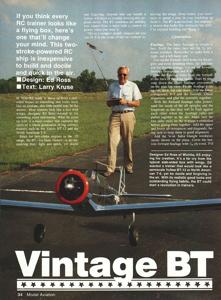
If you think every RC trainer looks like a flying box, here's one that'll change your mind. This two-stroke–powered RC ship is inexpensive to build and is docile yet quick in the air.
Design: Ed Ross Text: Larry Kruse
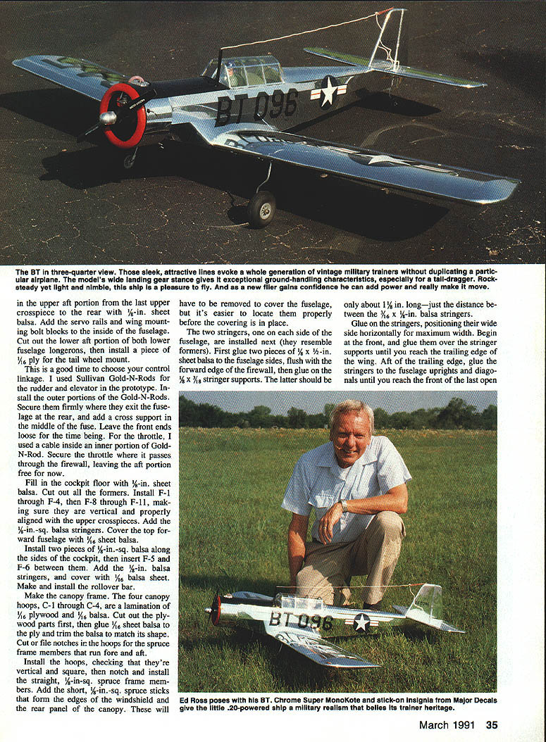
If you're ready to move up from a slab-sided trainer to something that looks more like an airplane, this little model may be the answer. Most trainers look like a box with wings; designer Ed Ross wanted to try something more interesting. What he came up with is a basic trainer that captures the spirit of a whole generation of big military trainers such as the Vultee BT-13 and the North American T-6.
Sized for two-stroke engines in the .20 range, the BT — for basic trainer — is an outstanding flier: light and quick, yet docile and forgiving. Anyone who can handle a trainer will have no trouble slowing this airplane down. The BT combines the stability you expect from a tutor with a reserve of power when you need it.
This is a compact model; chances are you can fit it in the trunk of the car without removing the wings. Even better, you won't have to spend a year in your workshop to build it. The BT is an unusual, fun airplane; a trainer that looks semiscale but isn't.
Construction
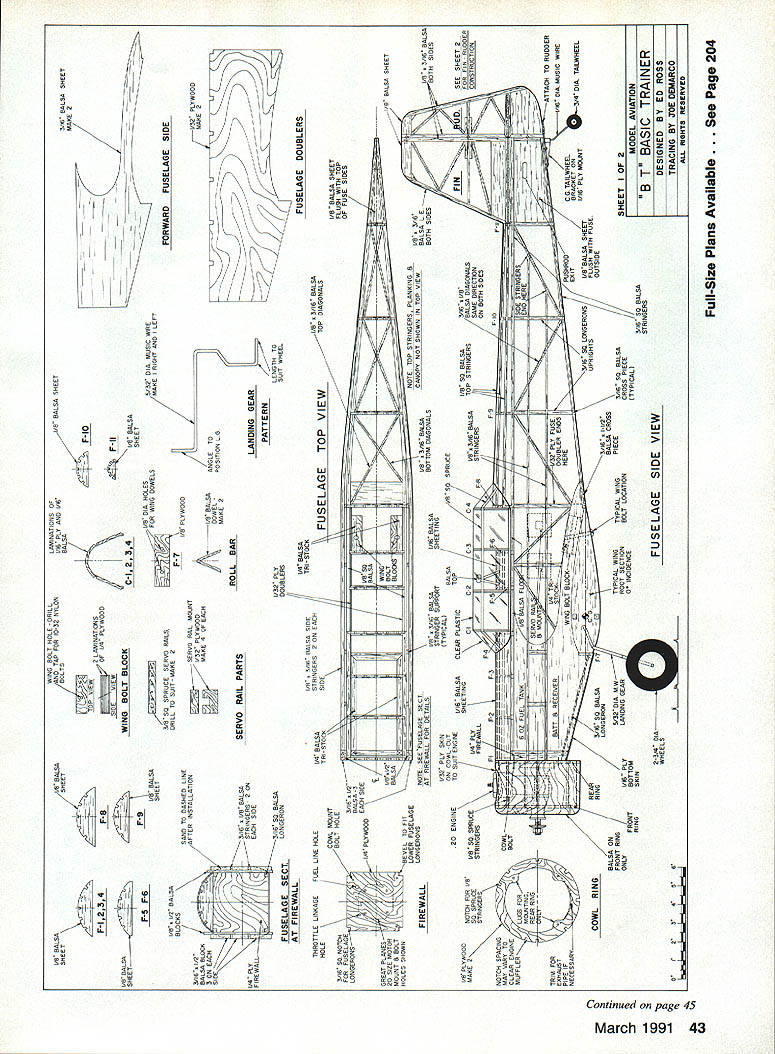
#### Fuselage
- The basic fuselage is simply a box. Build the sides, then add the 1/8-in. plywood doublers. Make both a right- and a left-hand side.
- Cut out the firewall. Drill holes for the engine and cowl mounting bolts, the fuel line and the throttle linkage. Cut out the forward fuselage crosspieces and F-7.
- Join the fuselage sides from the firewall to the back of the wing saddle. Pin the upper fuselage crosspieces on the plan top view, fit the fuselage sides against them (top side down), then add the lower crosspieces, F-7 and the firewall. Check alignment and glue the assembly together.
- With the forward fuselage sides joined, sand the inside of the aft uprights and the longerons so they will fit flush when the fuselage sides are pulled together at the tail. Ensure the two sides meet on the airplane's centerline before gluing. Add the upper and lower aft crosspieces and diagonals, keeping everything in good alignment.
- Add the 1/4-in. balsa triangle reinforcements shown on the plans. Cover the bottom forward fuselage with 1/16-in. plywood. Fill the cockpit floor with 1/8-in. sheet balsa.
- Cut out formers and install F-1 through F-4 and F-8 through F-11, making sure they are vertical and properly aligned with the upper crosspieces. Add 1/4-in.-sq. balsa stringers and cover the topward fuselage with 1/16-in. sheet balsa.
- Install two pieces of 1/8-in.-sq. balsa along the sides of the cockpit; insert F-5 and F-6 between them. Add 1/8-in. balsa stringers and cover with 1/16-in. balsa sheet.
- Make and install the rollover bar.
Canopy frame:
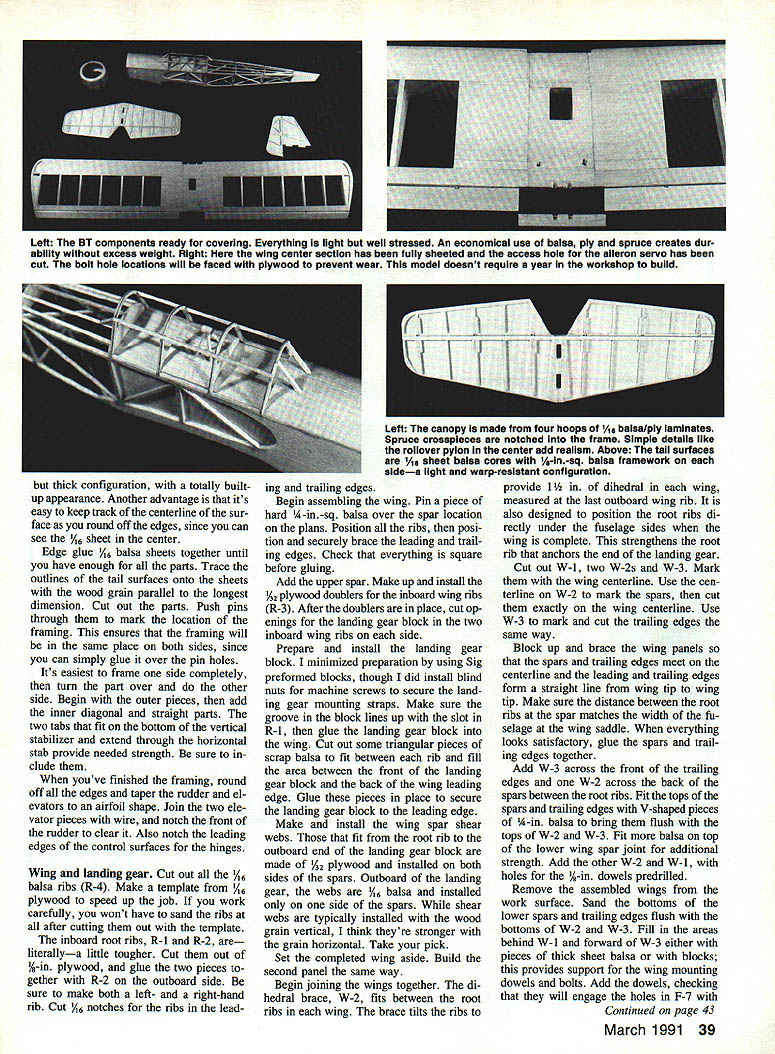
- The four canopy hoops (C-1 through C-4) are laminated from 1/16-in. plywood and 1/16-in. balsa. Cut out the plywood parts, glue 1/16-in. sheet balsa to the ply, and trim the balsa to match.
- Cut/file notches in the hoops for the spruce frame members that run fore and aft. Install the hoops, checking they're vertical; square-notch and install the straight 1/8-in.-sq. spruce frame members. Add short 1/8-in.-sq. spruce sticks to form the edges of the windshield and rear panel. The canopy will have to be removable; it is easier to locate and fit it before covering.
Stringers and cockpit finish:
- Install two stringers, one on each side of the fuselage. First glue two pieces of 3/32 x 3-1/2-in. sheet balsa to the fuselage sides flush with the forward edge of the firewall. Glue finger supports (about 1 in. long) at the spacing for the 1/16 x 1/8-in. balsa stringers.
- Glue on the stringers, positioning their wide side horizontally for maximum width. Begin at the front and glue them over the stringer supports until you reach the wing trailing edge. At the aft trailing edge glue the stringers to the fuselage uprights and diagonals until you reach the front of the last open area. Taper and trim stringers before gluing.
- Install 3/16-in. balsa blocks between and above/below stringers, flush with the forward face of the firewall; carve and sand the blocks to blend fuselage former top to flat fuselage bottom.
Radio and controls:
- Add servo rails and wing-mounting bolt blocks to the inside of the fuselage. Cut out the lower aft portion of both lower fuselage longerons, then install a piece of 1/16-in. ply for the tailwheel mount.
- Choose control linkages. The prototype used Sullivan Gold-N-Rods for rudder and elevator; install the outer portions and secure them firmly where they exit the fuselage at the rear. Add a cross support in the middle of the fuselage. Leave the front ends loose for now.
- For the throttle, a cable inside an inner portion of Gold-N-Rod can be used. Secure the throttle where it passes through the firewall, leaving the aft portion free for final hookup.
Antenna:
- Below the mast-type radio antenna, epoxy an inner Gold-N-Rod section to a piece of 1/16-in. plywood. Paint the exposed upper portion with Hobby Poxy Formula II to fuelproof it. Avoid gluing the antenna hole shut; sand smooth and dry-fit, then glue after covering the fuselage.
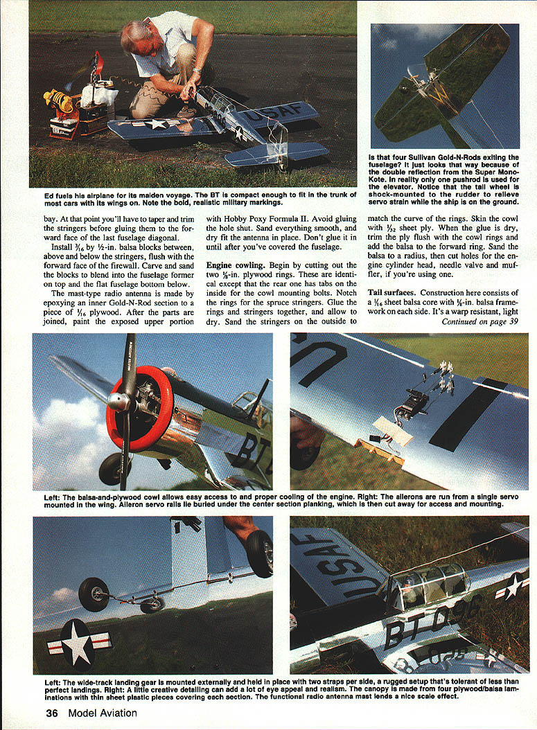
#### Engine cowl
- Cut two 3/32-in. plywood rings identical except the rear ring has tabs inside for cowl mounting bolts. Notch the rings for spruce stringers.
- Glue rings and stringers together; allow to dry. Sand the stringers outside to match the curve of the rings.
- Skin the cowl with 1/32-in. sheet ply; glue and dry, then trim ply flush with cowl rings and add a balsa forward ring. Sand the balsa to radius; cut holes for the engine cylinder head, needle valve and muffler being used.
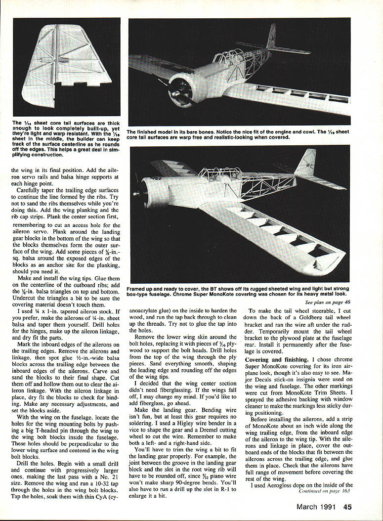
#### Tail surfaces
- Construct tail surfaces with a 1/16-in. sheet balsa core and 1/8-in. balsa framework sides. This makes them warp-resistant and light.
- Edge-glue 1/16-in. balsa sheets until you have enough for all parts. Trace outlines with the wood grain parallel to the longest dimension and cut out the parts.
- Push pins through the parts to mark the framing locations; this ensures the framing will be in the same plane on both sides.
- Frame one side completely, then turn the part over and do the other side. Begin with outer pieces, then add inner diagonal and straight parts. Include the two tabs that fit on the bottom of the vertical stabilizer and extend through the horizontal stab for added strength.
- Round off all edges and taper rudder and elevators to an airfoil shape. Join the two elevator pieces with wire and notch the front of the rudder to clear it. Notch the leading edges of the control surfaces for the hinges.
#### Wing and landing gear
- Cut all 1/8-in. balsa ribs (R-4). Make a template from 1/16-in. plywood to speed the job. For inboard root ribs (R-1 and R-2), cut from 3/32-in. plywood and glue the two pieces together with R-2 on the outboard side. Make left- and right-hand ribs. Cut 1/16-in. notches for the ribs in the leading and trailing edges.
- Assemble the wing: pin a piece of 1/8-in.-sq. balsa over the spar location on the plans, position all ribs, then position and brace the leading and trailing edges. Check squareness before gluing. Add the upper spar.
- Make and install 1/8-in. plywood doublers for the inboard wing ribs (R-3). After doublers are in place, cut openings for the landing gear block in the two inboard wing ribs on each side.
- Prepare and install the landing gear block (Sig preformed blocks were used in the prototype). Install blind nuts for machine screws if desired. Ensure the groove in the block lines up with the slot in R-1, then glue the block into the wing. Fill the area between the front of the landing gear block and the back of the wing leading edge with triangular pieces of scrap balsa to secure the block.
- Make and install wing spar shear webs. From the root rib to the outboard end of the landing gear block, webs are 3/32-in. plywood installed on both sides of the spars. Outboard of the landing gear, webs are 1/16-in. balsa installed on one side of the spars. Grain orientation (vertical or horizontal) is a builder choice.
- Build the second wing panel the same way. Join the panels using the dihedral brace W-2 to provide 1-1/2 in. of dihedral in each wing panel (measured at the last outboard wing rib). W-2 also positions the root ribs under the fuselage so the wing bolt is centered.
- Cut out W-1, two W-2s and W-3. Use the centerline marks to align and cut spars and trailing edges exactly on the centerline. Block up and brace the panels so spars and trailing edges meet on the centerline and the leading and trailing edges form a straight line from tip to tip. Ensure the distance between root ribs at the spar matches the fuselage width at the wing saddle. Glue spars and trailing edges together.
- Add W-3 across the front of the trailing edges and one W-2 across the back of the spars between the root ribs. Fit the tops of the spars and trailing edges with V-shaped pieces of 1/8-in. balsa to bring them flush with the tops of W-2 and W-3. Add reinforcement over the lower wing shear spar joint and install the other W-2 and W-1, predrilling holes for the 1/8-in. dowels.
- Remove assembled wings, sand the bottoms of the lower spars and trailing edges flush with the bottoms of W-2 and W-3. Fill areas behind W-1 and forward of W-3 with sheet balsa or blocks to support wing mounting dowels and bolts. Add the dowels, checking they will engage the holes in F-7 with the wing in its final position.
- Add aileron servo rails and balsa hinge supports at each hinge point. Carefully taper trailing-edge surfaces to continue the rib line; avoid sanding the ribs themselves. Add wing planking and rib cap strips. Plank the center section first, cutting an access hole for the aileron servo. Plank around the landing gear blocks so that the blocks form part of the outer surface; add 1/8-in. sq. balsa around exposed block edges as anchors for the planking.
- Make and install wing tips: glue them on the centerline of the outboard ribs and add 1/4-in. balsa triangles on top and bottom. Undercut the triangles slightly so covering material doesn't touch them.
- Ailerons: 1/4 x 1-in. tapered aileron stock was used in the prototype. Alternatively, make ailerons from 1/4-in. sheet balsa and taper them yourself. Drill hinge holes, make up aileron linkage, and dry-fit parts.
- Mark inboard edges of the ailerons on the trailing edges, remove ailerons and linkage, then spot-glue 1/2-in.-wide balsa blocks across the trailing edge between the inboard edges of the ailerons. Carve and sand blocks to final shape, hollow them out to clear aileron linkage, dry-fit with linkage and adjust for no binding.
- Wing bolt holes: with the wing on the fuselage, locate wing mounting bolt holes by pushing a T-headed pin through the wing to the wing bolt blocks inside the fuselage. Holes should be perpendicular to the lower wing surface and centered in the wing bolt blocks. Drill progressively larger, finishing with a No. 21 size. Remove wing, run a 10-32 tap through wing bolt block holes, soak holes with thin CA to harden wood, and run the tap back to clean threads. Replace lower wing skin around bolt holes with 1/8-in. plywood to support bolt heads; drill through ply pieces and sand smooth.
- If desired, fiberglass the wing center section for extra security; the prototype did not.
Landing gear and tailwheel:
- Bend landing gear wire (3/32 piano wire used) to shape; no soldering required. Make left- and right-hand sides.
- Trim the wing to fit the gear: round the joint between the groove in the landing gear block and the slot in the root rib as 3/32 wire won't make sharp 90° bends. Enlarge slots such as R-10 where needed.
- For a steerable tailwheel, cut down the back of a Goldberg tail wheel bracket and run the wire aft under the rudder. Temporarily mount the tail wheel bracket to the plywood plate at the fuselage rear; install permanently after covering.
Covering and finishing
- The prototype used chrome Super MonoKote for an iron-airplane look. Major Decals stick-on insignia were used on wing and fuselage; other markings were printed from MonoKote Trim Sheets. Spray the adhesive backing with window cleaner to make markings less sticky during positioning.
- Before installing ailerons, add a strip of MonoKote about 1 in. wide along the trailing edge from the inboard edge of the aileron to the wing tip. With ailerons and linkage in place, cover the outboard edges of the blocks that fit between ailerons across the trailing edge and glue them in place. Check full aileron movement before covering the rest of the wing.
- Inside the fuselage, Aeroglaze dope was used: clear dope on the cockpit, black on the floor and instrument panels, and olive drab elsewhere. Paint the inside of the cowl black, then finish it and the firewall with Hobby Poxy Formula II.
- Canopy: make the canopy by gluing thin plastic sheeting over the framework with Wilhold R/C-56—three pieces at the front and rear and one between each canopy hoop. Cover canopy seams with 1/4-in.-wide strips of chrome MonoKote trim film, except the bottom of the windshield seam which used black trim tape.
- Install the antenna mast from inside the fuselage, paint it black and fuelproof with clear polyurethane.
Final assembly and flying
- Wrap a 6-oz. Sullivan fuel tank in foam rubber and install it as high and as far forward in the fuselage as possible.
- Wrap the radio receiver and batteries in foam rubber and install them below the fuel tank. Install servos and secure rudder and elevator pushrods.
- Recommended control throws (approximate):
- Rudder: ±3/8 in.
- Elevator: ±3/8 in.
- Ailerons: ±1/4 in.
- Check the center of gravity and add weight if necessary to match the plans. Test-run the engine to ensure the throttle control works properly: the servo should open the throttle fully and stop the engine with the throttle closed plus full low-throttle trim.
- Note: removing and replacing the fuel line on the carburetor for refueling is difficult with the cowling in place; eyebrow tweezers (small, skinny pliers) make it easier.
- The prototype's first flights (test pilot Jim Todd) showed the BT tracked straight on takeoff and required only a bit of right rudder trim to fly hands-off. At half throttle it was gentle and stable; adding power made it perform briskly. On final approach the model was steady and tracked straight for easy wheel landings. Ground handling was exceptionally good for a tail-dragger.
Build one and you're likely to agree — the BT is an unusual, fun trainer that flies as well as it looks.
Transcribed from original scans by AI. Minor OCR errors may remain.

