
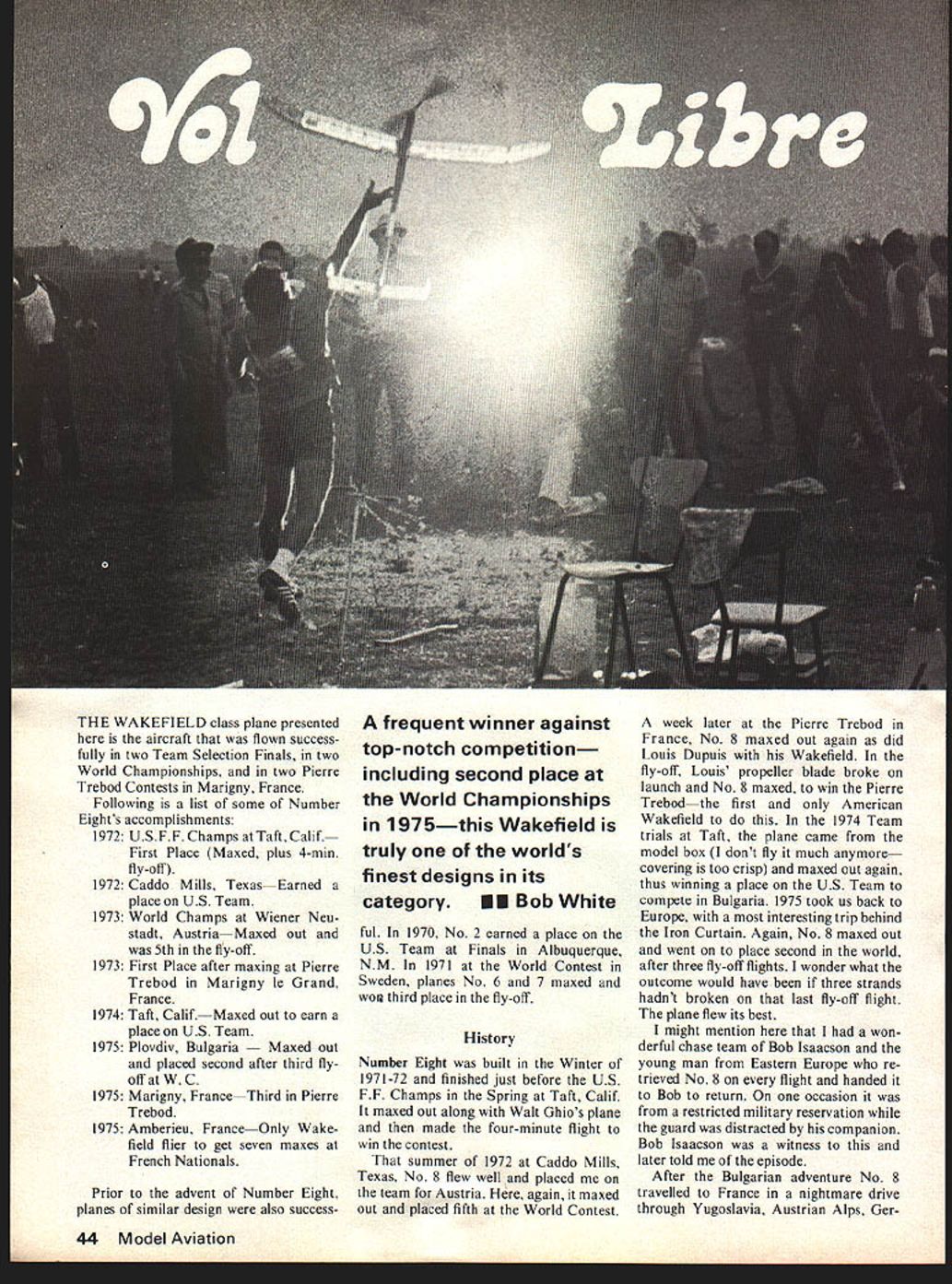
Vol Libre
THE WAKEFIELD class plane presented here is the aircraft that was flown successfully in two Team Selection Finals, in two World Championships, and in two Pierre Trebod Contests in Marigny, France.
Following is a list of some of Number Eight's accomplishments:
1972: U.S.F.F. Champs at Taft, Calif.—First Place (Maxed, plus 4-min. fly-off).
1972: Caddo Mills, Texas—Earned a place on U.S. Team.
1973: World Champs at Wiener Neustadt, Austria—Maxed out and was 5th in the fly-off.
1973: First Place after maxing at Pierre Trebod in Marigny le Grand, France.
1974: Taft, Calif.—Maxed out to earn a place on U.S. Team.
1975: Plovdiv, Bulgaria—Maxed out and placed second after third fly-off at W.C.
1975: Marigny, France—Third in Pierre Trebod.
1975: Amberieu, France—Only Wakefield flier to get seven maxes at French Nationals.
Prior to the advent of Number Eight, planes of similar design were also successful.
A frequent winner against top-notch competition—including second place at the World Championships in 1975—this Wakefield is truly one of the world's finest designs in its category. — Bob White
In 1970, No. 2 earned a place on the U.S. Team at Finals in Albuquerque, N.M. In 1971 at the World Contest in Sweden, planes No. 6 and 7 maxed and won third place in the fly-off.
History
Number Eight was built in the Winter of 1971-72 and finished just before the U.S.F.F. Champs in the Spring at Taft, Calif. It maxed out along with Walt Ghio's plane and then made the four-minute flight to win the contest.
That summer of 1972 at Caddo Mills, Texas, No. 8 flew well and placed me on the team for Austria. Here, again, it maxed out and placed fifth at the World Contest.
A week later at the Pierre Trebod in France, No. 8 maxed out again as did Louis Dupuis with his Wakefield. In the fly-off, Louis' propeller blade broke on the launch and No. 8 maxed, to win the Pierre Trebod—the first and only American Wakefield to do this. In the 1974 Team trials at Taft, the plane came from the model box (I don't fly it much anymore—the covering is too crisp) and maxed out again, thus winning a place on the U.S. Team to compete in Bulgaria. 1975 took us back to Europe, with a most interesting trip behind the Iron Curtain. Again, No. 8 maxed out and went on to place second in the world, after three fly-off flights. I wonder what the outcome would have been if three strands hadn't broken on that last fly-off flight. The plane flew its best.
I might mention here that I had a wonderful chase team of Bob Isaacson and the young man from Eastern Europe who retrieved No. 8 on every flight and handed it to Bob to return. On one occasion it was from a restricted military reservation while the guard was distracted by his companion. Bob Isaacson was a witness to this and later told me of the episode.
After the Bulgarian adventure No. 8 travelled to France in a nightmare drive through Yugoslavia, Austrian Alps, Ger many and on to Marigny for the second time. Number Eight missed the first max by two seconds, due to my fatigue and error in judgment, but still went on to place third in the Pierre Trebod.
After a week of rest and visiting in France with our friends, Pierre and Josette Chaussebourg, old No. 8 flew, unofficially, as a guest of the French in their Nationals, near Lyon, France. It made seven maxes, which was one more max than the winner of the competition.
We will not be in this year's World Contest, but a plane of similar design will be flown there by Dr. Robert Piserchio of San Diego, Calif., member of the 1977 Team.
No one ever does much unaided by others, and I must mention Bill Bogart for all his technical advice and help on the design. We have met each week for years and talked about airplanes—why they fly, and why they don't fly. Also, Fudo Takagi has helped to keep my head screwed on straight and provided me with his best motors and his good air-picking advice. But most of all I have my wife, Toni, who likes to go flying with me anywhere, even at the monthly turkey shoots, when I bomb out in a downer and come in last!
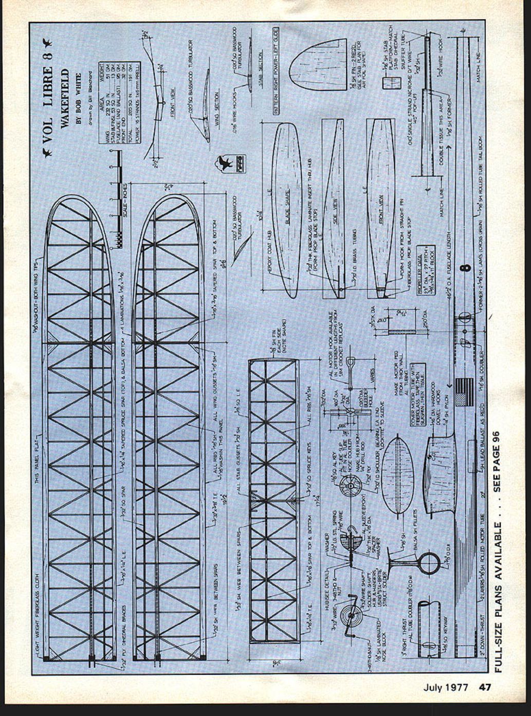
As you will notice by the plans, I am presenting my No. 8 (Vol Libre) Wakefield for your criticism and information. (Vol Libre means free flight in French—also a symbol of the FAI.) I feel that a free exchange of information is quite important for the health and growth of our sport. This is the most successful version of my design, and, as you can see from the drawing, it is not a radical departure from many Wakefields flown today. At present I have made 18 versions of this design. Let me assure you, however, they do vary a great deal in how they fly, even when the attempt is made to build identical airframes.
The Wakefield, at best, is a frustrating experience. The performance limitations restrict the flight potential to such an extent that a max (180 seconds) cannot be obtained without good air and good power. Maybe this is what keeps us going. I feel that one of the most interesting parts of Flying is the testing of a new variation in design.
I usually build two planes at the same time and spend about six months in construction. As you can see, I am not a fast builder and I work only when I feel like it. This is important for us "old-timers" because pushing yourself to build makes a chore of it, and I have been building for more years than I care to admit.
The main considerations are classic for any free-flight plane: low drag and high lift, or moderate lift as in No. 8.
Construction
Wing
This is a complex structure and must be made of the best possible wood, all straight and hard toward the center of the inner panels, then gradually lighter to the tip dihedral break and lighter yet, but not soft, at the tips. The ribs are C-grain and cut so that the straight portion of the grain is near the trailing edge. The trailing edge of the inner panels is hard, straight, B-grain balsa. The spars are tapered as shown on the plan. The top one is made of spruce, and the bottom spar is of very hard balsa or spruce. The leading edge is of medium to hard balsa and, above all, straight. The wing-tip outline is laminated on a form and glued with Titebond.
Assembly of the wing is done in the following sequence: The leading edge, the ribs, and the trailing edge for each inner panel are laid out and glued on a flat board (propping up the trailing edge to conform to the wing section). Let dry for a day, then remove from board and sand with formed sanding blocks to near actual shape. The wing tips are built and sanded, the wing then assembled together. The ribs are notched and the spars are installed.
The final shaping is now started. Use sanding blocks and templates to get the shape, being very careful to duplicate the leading edge as shown. This is the important part of the wing. After final shaping, use thin Titebond to re-glue all the joints. This wing must have all perfect glue joints. Check the wing for warps and straighten as necessary and then let it age for two or three weeks. As will be noticed, the plans I am presenting — No. 8, Vol Libre Wakefield — are for criticism and information. Vol Libre means "free flight" (French) and also symbolizes the FAI. Feel free to exchange information; it is quite important to the health and growth of the sport. The successful version of the design you can see in the drawing is a radical departure from Wakefields flown today. To date I have made 18 versions of the design.
Let me be sure, however, that they vary a great deal. If you attempt to build identical airframes, Wakefield can be the most frustrating experience. Performance limitations restrict flight potential to such an extent (max 180 seconds) that it cannot be obtained without good air and good power. Maybe that is what keeps us going — the feeling that the interesting parts remain.
No. 8 never does much unaided. Others must be mentioned: Bill Bogart for technical advice and help in design; Fudo Takagi, who has helped keep my head screwed straight and provided the best motors and good air‑picking advice; and my wife Toni, who likes to go flying anywhere.
Vol Libre/White
continued from page 46
formers in the fuselage. I should have installed the formers in the fuselage first as they could be used as templates when sanding to shape.
I covered the foam with Silkspan because of its wet strength, needed when trying to smooth it out with the white glue mixture. Perhaps tissue would work just as well and be lighter.
The model was then completely finished prior to the foam dissolving attempt. It was a joy to put on details, such as trim colors, inked outlines of control surfaces, working against a solid foam core. I now had visions of a peanut plane that would not have holes in the covering from weed and tree contact to be patched.
A hypodermic type syringe was used to apply the gasoline deep into the fuselage and also through some holes in the wings. The gasoline did a good job of dissolving the foam without attacking the finish paint. Most of the gel residue from the foam was removed with a cotton swab. Not all of the foam, after it is dissolved, can be removed as it coats the inside of the Silkspan with a coating of styrene. Not too much weight can be removed by this method; be careful in covering the foam in the first place.
The plane was a bit heavy, for a peanut-sized airplane. The Silkspan saturated with the Knox gelatin-white glue mixture is really strong, but tends to be a little brittle. Perhaps another filler in place of the gelatin is in order. The method does work and I feel justifies building other peanuts of this type.
Every part of the country has a K‑Mart, hardware or drug store that carries all the necessary materials. I urge all the modelers to build their favorite scale plane via the styrofoam method, be it control line, free flight, or just a shelf model for display only. If you won't try a complete model of foam, at least make a styrofoam pilot for your next scale job. We try hard to duplicate an exact scale model and then, strangely, forget the scale pilot.
I am sure modelers can come up with better ideas, methods or materials, if I can only heighten your interest. Let your mind wander, ponder, scheme, plan. I would be most anxious to hear your ideas. My address is 1371 Ashover, Bloomfield Hills, Mich. 48013.
Editor's Note: The reader is directed to the December 1976 issue which contained an illustrated article, Super Fiberglass Fuselages — by Dan Mauch. His system was basically similar and more suited for Pattern and Scale RC types.
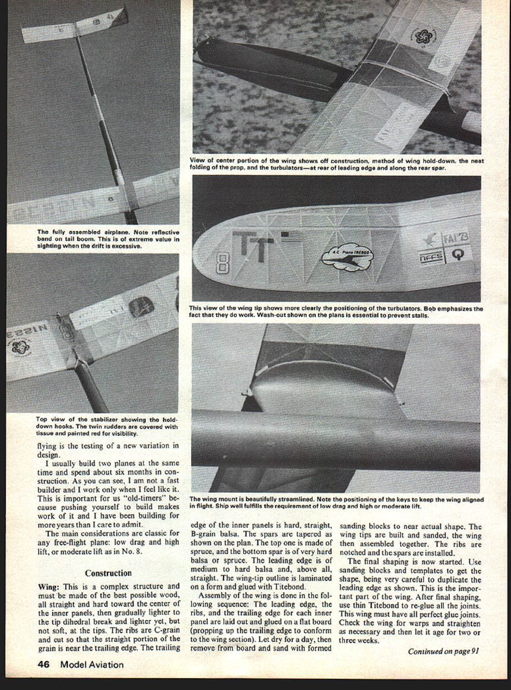
Covering: The wing is covered with good quality Japanese tissue and doped lightly with moderately plasticized dope, just enough to seal the tissue. If you live in a damp climate, a little more dope or Scotchguard spray will seal it from moisture. Before covering, the wing structure is doped with two coats of moderately thinned nitrate dope on the contact area of the tissue (all the outside surfaces). This is important and adds much strength to the structure. Use as little dope as possible on the covering because too much dope will warp the wing. After covering and doping, the wing can be straightened, if necessary, and left to cure again. Please observe the note on wash-out on the wing tips. With any less wash-out, the plane will have stall problems. If you fly in turbulent air, you may have to add 1/32 in. more wash-out on each tip.
Stabilizer: This is constructed the same as the wing, except the wood should be lighter, but not soft. Follow the same procedure for covering.
Rudders: These are very soft C‑Grain and are sanded to shape and glued to the stab after the stab is covered but before water shrinking. Cover the rudders with tissue and paint red or some high visibility color.
Motor Tube: This is made of two laminations of hard A‑Grain balsa, formed on a 1 1/4 in. form, from a 4‑in‑wide sheet of balsa.
Tail Boom: This is made on a tapered form of medium A‑Grain balsa. The tail boom and tail of the plane must be kept light and strong at the same time, so care must be taken with this wood and precision of construction. No poor part fitting or bad glue joints here.
Wing Mount: This is made of medium-weight sheet balsa and carved balsa blocks for fillets. Assemble the tail boom to the motor tube and glue the wing mount in place, before any covering. Next, coat the motor tube with two coats of thick dope and the tail boom with one coat of thin dope. Cover the motor tube with glass cloth, using nitrate dope. Sand this smooth and then cover with heavy Silkspan. Cover the tail boom with Japanese tissue — double cover one inch wide where the rear bulkhead is located. Pour nitrate dope inside the motor tube after everything is dry and slosh around, then pour out and hang from the tail, so it can drain overnight. Be sure the bulkhead is already installed at the end of the motor tube.
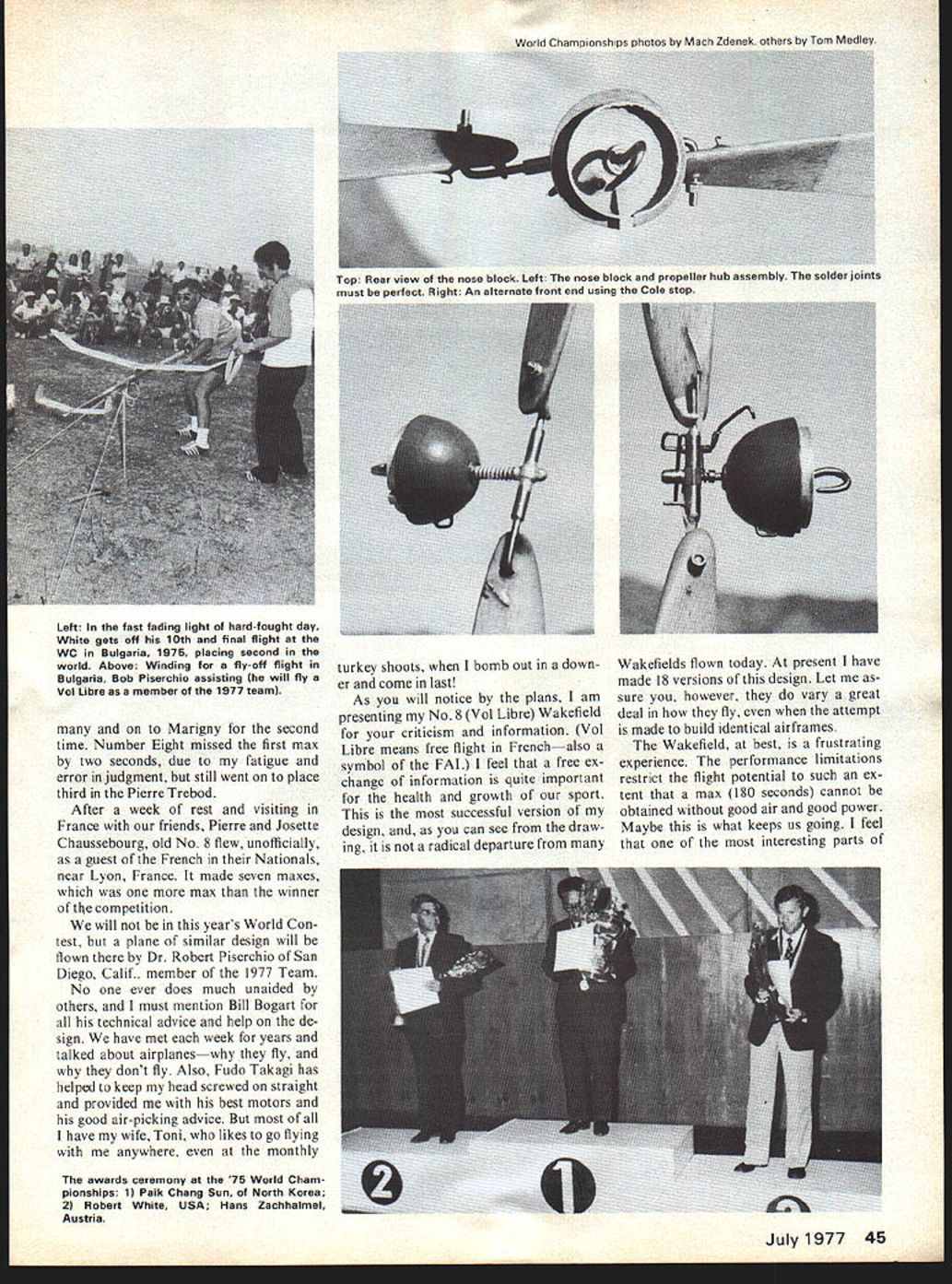
Front End Assembly: This is made as shown on the plan, using good steel for the prop hub, and extreme care in soldering. Tin all parts before assembly and soldering. Use good piano wire for shaft and hangers. The bearings need to be the shielded type and lubricated with light oil.
Propeller: The prop is a precise job, so take your time. Use rock-hard balsa, cut to similar accurate shape, with similar grain structure in each blade. With the present rubber situation, you may need to make the blade a little narrower after the complete prop is carved. Keep the blades as thin as possible because this seems to work best. A good rule to follow: If too thick, they don't work well and, if too thin, they break. I finish the blade with a few coats of plasticized nitrate dope, but don't fill the grain in the wood.
The turbulator does work and keeps the prop pulling in the slower portion of the power run. The winding loop is made from solid heat-treated aluminum, or it may be ordered from Jim Crockett.
Flying: No. 8 is designed to fly "right" under power, and glide "left." A glide to the right is not recommended because I have never had a plane of this design fly well to the right in the glide.
Tape the ballast to the motor tube (the ballast consists of a lead weight, making up the difference between the weight of the plane and 190 grams) in a location so that the plane balances as shown on the plan. Glide the plane over a soft area. (We don't have tall grass where I live, just cactus and sagebrush.) Put shims under the stab until the plane glides. Adjust the rudder tabs to get a wide left turn. Wind about 50 turns and gently launch straight ahead. Make thrust adjustments to get a moderate, but not too steep, right turn. With more power, the climb pattern should be straight and steep at first, then turning to the right, tightening as the power decreases; then, near the end of the power run, the rudders turn the plane to the left for the glide. You can tighten the glide turn after the climb is correct.
I use 16 strands of strong Pirelli and wind 330 to 340 turns. A fully wound motor should have 110 to 120 in./oz. of torque. With FAI rubber I use 14 strands and wind about 310 to 320 turns. This should give a torque of 120 to 130 in./oz. I should mention here that there are many factors to consider when winding motors to maximum. The rubber must be well broken in and test wound to find out where the actual breaking point takes place.
I wind with a winding tube to protect the plane, and to help remove broken motors. The motor tube will stand a broken motor, but it is difficult to remove it. The shock on other parts is also lessened by the motor tube.
Flying a Wakefield is both a joy and a frustration but, above all, it is an unending challenge. It is never easy to make a good flight. As with most things we do in life, the more difficult the task the greater the reward.
Transcribed from original scans by AI. Minor OCR errors may remain.

