
Volksplane
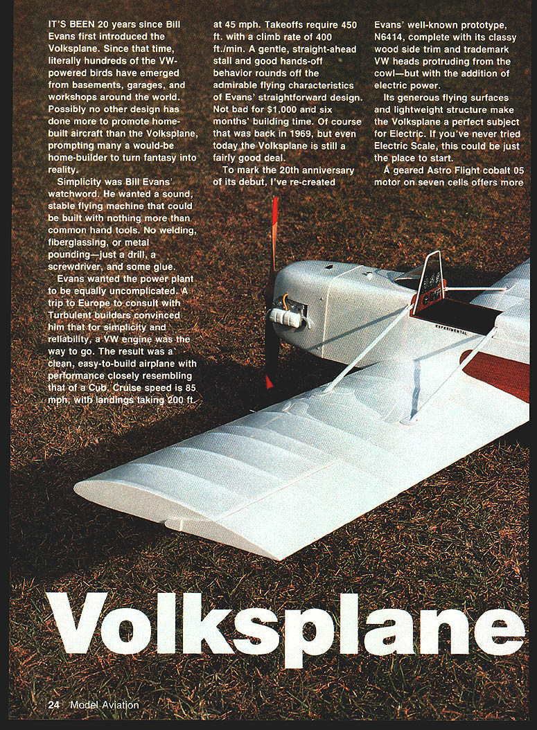
It's been 20 years since Bill Evans first introduced the Volksplane. Since that time, literally hundreds of the VW‑powered birds have emerged from basements, garages, and workshops around the world. Possibly no other design has done more to promote home‑built aircraft than the Volksplane, prompting many a would‑be home‑builder to turn fantasy into reality.
Simplicity was Bill Evans' watchword. He wanted a sound, stable flying machine that could be built with nothing more than common hand tools—no welding, fiberglassing, or metal pounding—just a drill, a screwdriver, and some glue. He also wanted the power plant to be uncomplicated; after consulting with Turbulent builders in Europe, he settled on the VW engine for simplicity and reliability.
The result was a clean, easy‑to‑build airplane with performance closely resembling that of a Piper Cub: cruise about 85 mph, landings in roughly 200 ft. at 45 mph, takeoffs about 450 ft., and a climb rate near 400 ft./min. A gentle, straight‑ahead stall and good hands‑off behavior round out the admirable flying characteristics of Evans' straightforward design. Not bad for roughly $1,000 and six months' building time back in 1969—and even today the Volksplane is still a fairly good deal.
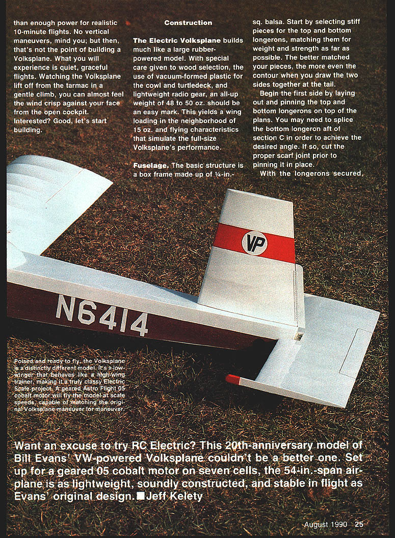
To mark the 20th anniversary of its debut, this recreation of Evans' prototype N6414 includes the classic wood side trim and the trademark VW heads protruding from the cowl—but with electric power. Its generous flying surfaces and lightweight structure make the Volksplane an excellent subject for electric conversion. A geared Astro Flight cobalt .05 motor on seven cells offers more than enough power for realistic 10‑minute flights: quiet, graceful flying that simulates the full‑size aircraft.
—Jeff Kelety
Construction
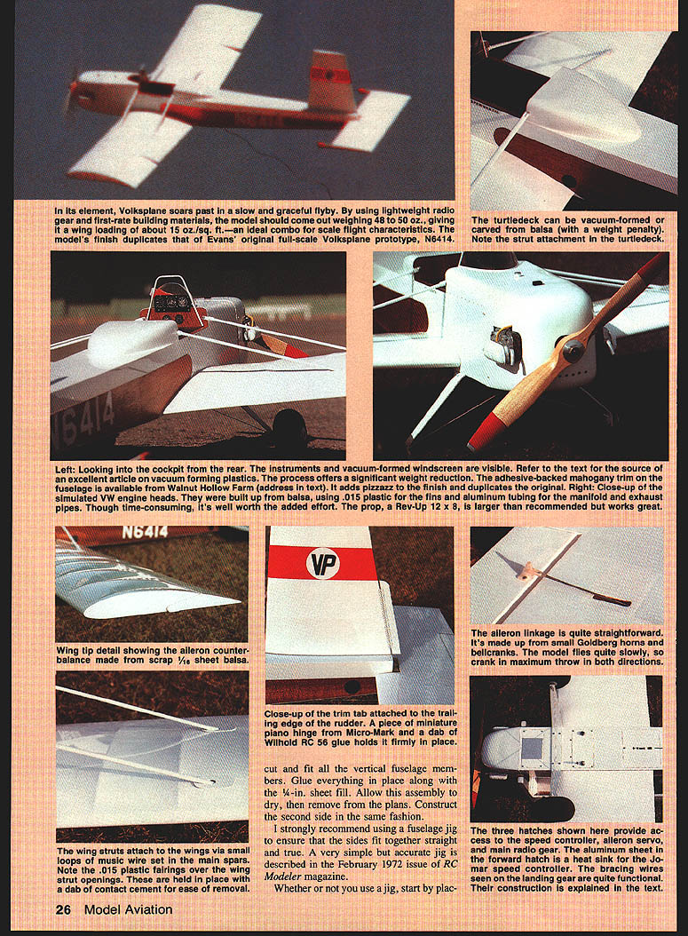
The Electric Volksplane builds much like a large rubber‑powered model. With careful wood selection, vacuum‑formed plastic for the cowl and turtledeck, and lightweight radio gear, an all‑up weight of 48–50 oz. is realistic. This yields a wing loading around 15 oz./ft.² and flying characteristics that simulate the full‑size Volksplane.
Fuselage
- Basic structure: a box frame made of 1/4‑in. sq. balsa.
- Select stiff, well‑matched pieces for the top and bottom longerons so the two fuselage sides draw together evenly at the tail.
- Build both fuselage sides upside down on the building board. Lay out and pin the top and bottom longerons on the plans. If necessary, splice the bottom longeron aft of section C with a scarf joint before pinning.
- Glue in uprights and crosspieces. Glue crosspieces at each station just aft of section C.
- Dry‑fit the two sides together at the tail, then glue the end crosspieces to ensure a straight fuselage. Mark and drill holes for the rudder post before adding formers (see below for hole size).
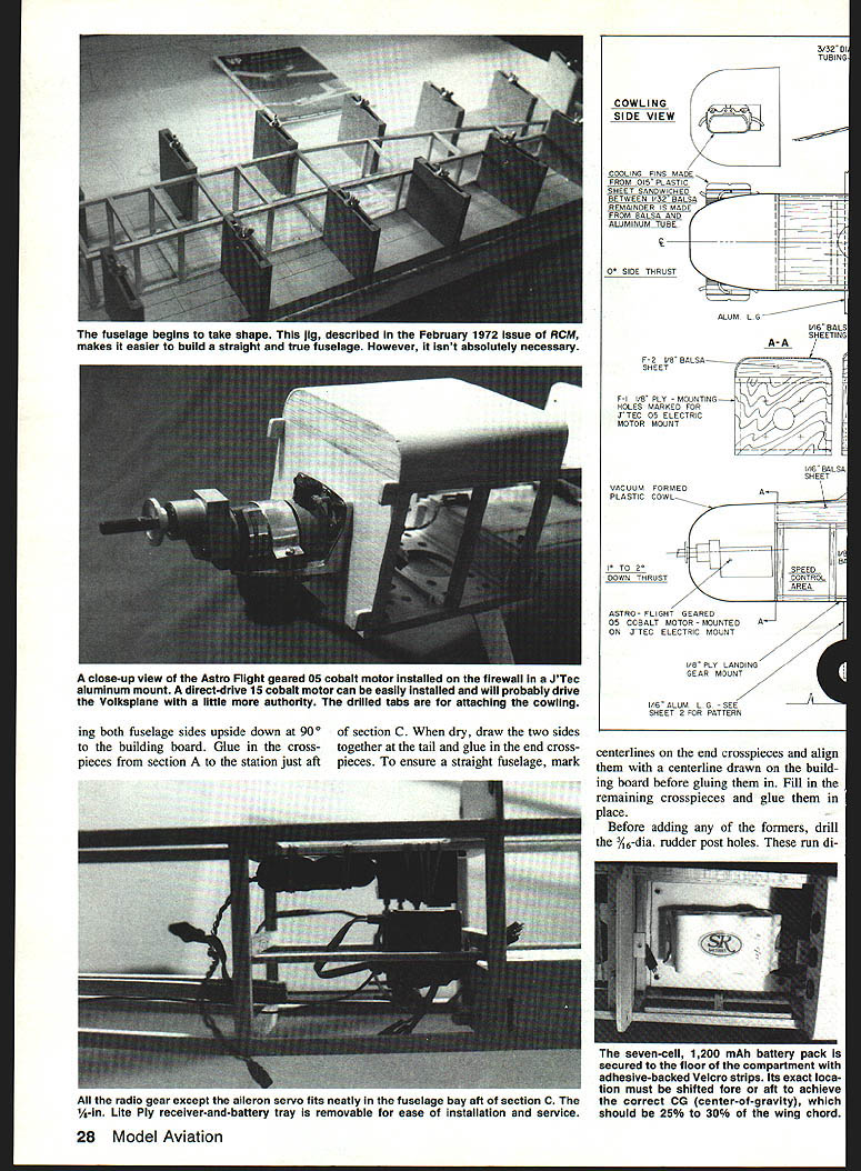
- A simple fuselage jig (Model Aviation/RCM Feb. 1972) makes building a straight fuselage easier but is not absolutely required.
Notes on motor and mounting:
- The prototype uses a geared Astro Flight cobalt .05 motor on seven cells. A JTEC aluminum mount for a direct‑drive .15 cobalt motor can be fitted and will give a bit more authority.
Radio and battery:
- Radio gear (except the aileron servo) fits in the fuselage bay aft of section C. A removable 1/8‑in. lite‑ply receiver/battery tray eases installation and service.
- Use a seven‑cell, 1,200 mAh battery pack secured to the floor with adhesive‑backed Velcro. Shift its fore/aft position to achieve the correct CG: 25%–30% of wing chord.
Construction details:
- Cut and fit all vertical fuselage members and 1/4‑in. sheet fill. Glue in place and allow to dry; then remove the assembly from the plans and construct the second side the same way.
- Place both fuselage sides upside down on the building board. Glue crosspieces from section A to the station just aft of section C. Dry‑fit, draw the sides together at the tail, and glue the end crosspieces.
- Align centerlines of the end crosspieces with a centerline drawn on the building board before gluing to ensure straightness.
- Before adding formers, drill 5/32‑in. dia. holes to accept the rudder post.
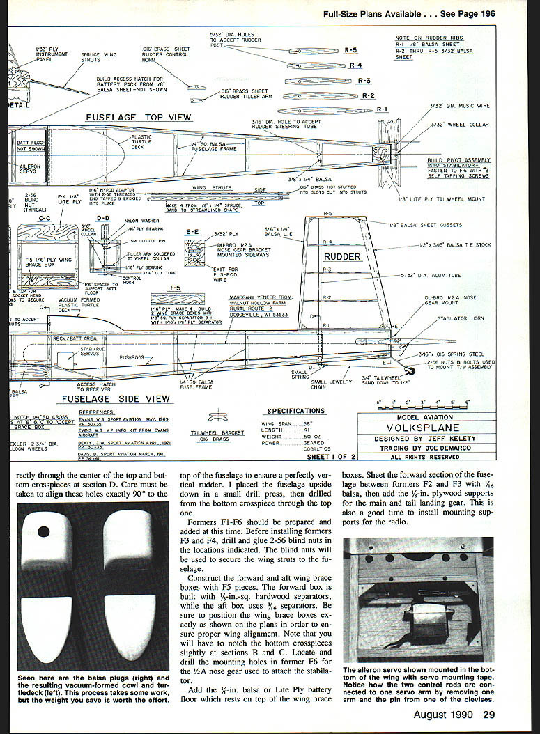
- Drill through the center of the top and bottom crosspieces at section D, carefully aligning holes 90° to the top of the fuselage to ensure a vertical rudder. A small drill press works well for this.
- Prepare and add formers F1–F6. Before installing F3 and F4, drill and glue 2‑56 blind nuts where indicated for the wing struts.
- Build forward and aft wing brace boxes with F5 pieces: the forward box uses 1/8‑in.‑sq. hardwood separators; the aft box uses 1/16‑in. separators. Position them exactly as shown on the plans—note the need to notch bottom crosspieces at sections B and C.
- Locate and drill mounting holes in former F6 for the 1/2A nose gear used to attach the stabilator.
- Add a 1/8‑in. balsa or lite‑ply battery floor resting on the wing brace boxes. Sheet the forward fuselage between F2 and F3 with 1/16‑in. balsa, then add 1/8‑in. plywood supports for main and tail landing gear. Install radio mounting supports now.
- Complete the fuselage by cutting slits in the 1/4‑in. balsa fill to accept wing braces and aileron pushrods.
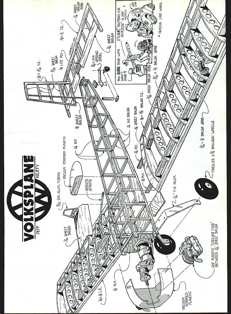
Diagram labels and notes:
- Vacuum‑formed plastic cowl
- Cooling fins made from .015 plastic sheet sandwiched between 1/32‑in. balsa
- Vacuum‑formed plastic turtledeck to accept receiver/battery area
- Access hatch to receiver/servos
- Receiver/battery area
- 1/8‑in. ply
- 1/8‑in. balsa
- 1/16‑in. ply
- 1/16‑in. balsa sheet
- 3/32‑in. sheet balsa ribs
- 3/16‑in. x 1/2‑in. balsa spar
- 3/4‑in. tailwheel
- 2‑1/16" T‑6 alum. (landing gear component)
- 1/8‑in. ply landing gear mount
- Trexler 2‑3/4‑in. balloon wheels
- 3/32‑in. dia. brass tube (rudder steering tube)
- 3/32‑in. music wire
- Wheel collar
- Rudder tiller arm
- Stabilator horn
- 3/32‑in. dia. holes to accept rudder post (where indicated on plan)
Cowl, turtledeck, and windshield
- The cowl and turtledeck can be hollowed‑out balsa or vacuum‑formed plastic. Vacuum forming saves considerable weight and allows direct painting. See Steve Gray's vacuum‑forming article (Model Builder, Mar. 1987) for guidance.
- Include dummy VW heads and valve covers for realism. Prototype heads were carved from balsa, with .015 plastic fins and aluminum tubing for the manifold and exhaust pipes.
- The windshield can be vacuum formed or stretch‑formed using heated acetate over a balsa mold.
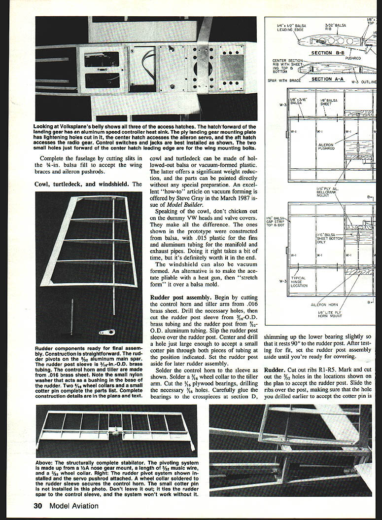
Rudder post assembly
- Cut the control horn and tiller arm from .016‑in. brass sheet and drill the necessary holes.
- Cut the rudder post sleeve from 3/8‑in. O.D. brass tubing and the rudder post from 5/32‑in. O.D. aluminum tubing. Slip the sleeve over the post.
- Center and drill a hole large enough for a small cotter pin through both tubes at the indicated position. Set aside.
- Solder the control horn to the sleeve. Solder a 3/16‑in. wheel collar to the tiller arm.
- Cut 1/8‑in. plywood bearings and drill 3/32‑in. holes. Glue bearings to crosspieces at section D; shim the lower bearing slightly so it rests true at 90° to the rudder post.
- After checking fit, set the rudder post assembly aside until covering.
Rudder
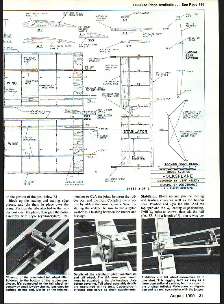
- Cut ribs R1–R5. Drill the 3/32‑in. holes where shown on the plan to accept the rudder post.
- Slide ribs over the post, aligning the cotter‑pin hole as indicated on the plans.
- On the portion of the post below R1, block up leading and trailing edges and pin them in place over the plans. Position the ribs attached to the post, then glue the assembly with thin CyA. CyA the joints between the rudder post and ribs.
- Add corner gussets. When installing the rudder, use a nylon washer as a bushing between the rudder and fuselage.
Stabilator
- Block up and pin the leading and trailing edges and the bottom spar. Position and CyA the ribs in place.
- Add the top spar and the 1/8‑in. leading‑edge sheeting. Drill 3/32‑in. holes as shown, then add half ribs S3.
- Slip a length of 3/32‑in. music wire between the half ribs with the Du‑Bro 1/4 nose‑gear mount and wheel collar in place, then epoxy the wire in position.
- Finish by adding 1/16‑in. balsa webbing and ballast ribs S2.
Main landing gear
- Fabricate gear from 1/16‑in. aluminum. Trexler balloon tires mount on 6‑32 bolts used as axles and secured with nuts on both sides of each gear leg.
- Drill two holes to accept .030‑in. bracing wires. Crimp and solder USA solder lugs to the ends of each bracing wire and mount the lugs on the 6‑32 axles.
- Draw each wire through its opposite rigging hole, leaving an inch or so of excess. Solder a small length of .030‑in. I.D. tubing flush against the outside of each side of the gear—make a solid solder joint as these bracing wires are functional. Trim off excess wire.
Tail wheel assembly
- Cut the tail wheel bracket from .016‑in. brass, drill the holes, and bend the bracket as shown.
- Solder a length of 3/32‑in. I.D. brass tubing to the base to accept the 2‑56 mounting screw.
- Use a Perfect #4 wheel, sanded down to 1/2‑in. diameter, mounted on a 1/8‑in. brad.
- The tail wheel assembly can be attached with a length of spring steel from the CB Associates small tail wheel assembly. Using the entire CB unit saves time but won't be quite scale.
- To complete the tail wheel, run light costume jewelry chain or steel fishing leader with small springs on one end from the tail wheel to the tiller arm.
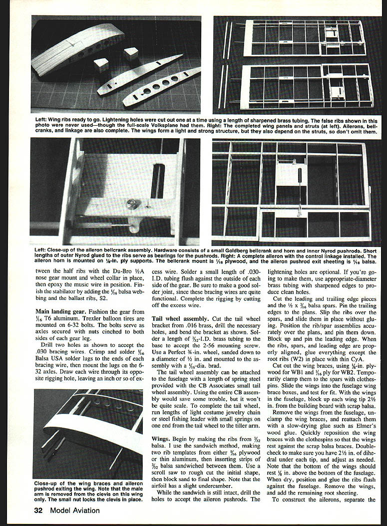
Wings
- Ribs: Make ribs from 3/32‑in. balsa using the sandwich method—two templates (1/16‑in. plywood or thin aluminum) with strips of 3/32‑in. balsa between. Rough‑cut on a scroll saw, then block sand to final shape. The airfoil has slight undercamber.
- While the sandwich is intact, drill holes for the aileron pushrods. Lightening holes are optional—if used, make them with die‑maker brass tubing for clean edges.
- Cut leading and trailing edges and 1/2 x 3/16‑in. balsa spars. Pin the trailing edges to the plans, slip ribs over the spars, position assemblies, and pin. Block up and pin the leading edge.
- When aligned, glue everything except root ribs (WB2) with thin CyA.
- Cut wing braces: 1/8‑in. ply for WB1 and 1/16‑in. ply for WB2. Temporarily clamp wing halves at the root with clothespins and test fit in the fuselage wing brace boxes.
- With the wings in the fuselage, block up each wing tip 2‑1/2 in. from the building board using scrap balsa. Remove wings, unclip wing braces, then reattach braces with a slow‑drying glue (Elmer's). Reposition quickly so wings rest against the scrap braces. Confirm 2‑1/2 in. dihedral under each tip and that the bottom of the wing sits 1/8 in. above the fuselage bottom.
- When dry, glue ribs flush against the fuselage, remove wings, and add remaining root sheeting.
- Ailerons: separate aileron ribs from wing ribs, sand and finish, install hinges and control horns per plans, then rig pushrods to the bellcrank and test for smooth, full movement.
- Insert small loops of .047‑in. music wire into the spars for attaching struts; add 1/8‑in. plywood spar braces to reinforce these sections.
Wing lock screws
- Wings are secured using 2‑56 x 1/4‑in. socket‑head screws set 1/8 in. into each forward wing brace box.
- Insert both wings, ensure flush fit, then drill and tap a 2‑56 hole into each forward wing brace box per section B‑B.
- Countersink holes in the balsa crosspiece so screw heads are flush with the fuselage bottom.
- Do not fly without the wing lock screws; they should hold the wings firmly without slop.
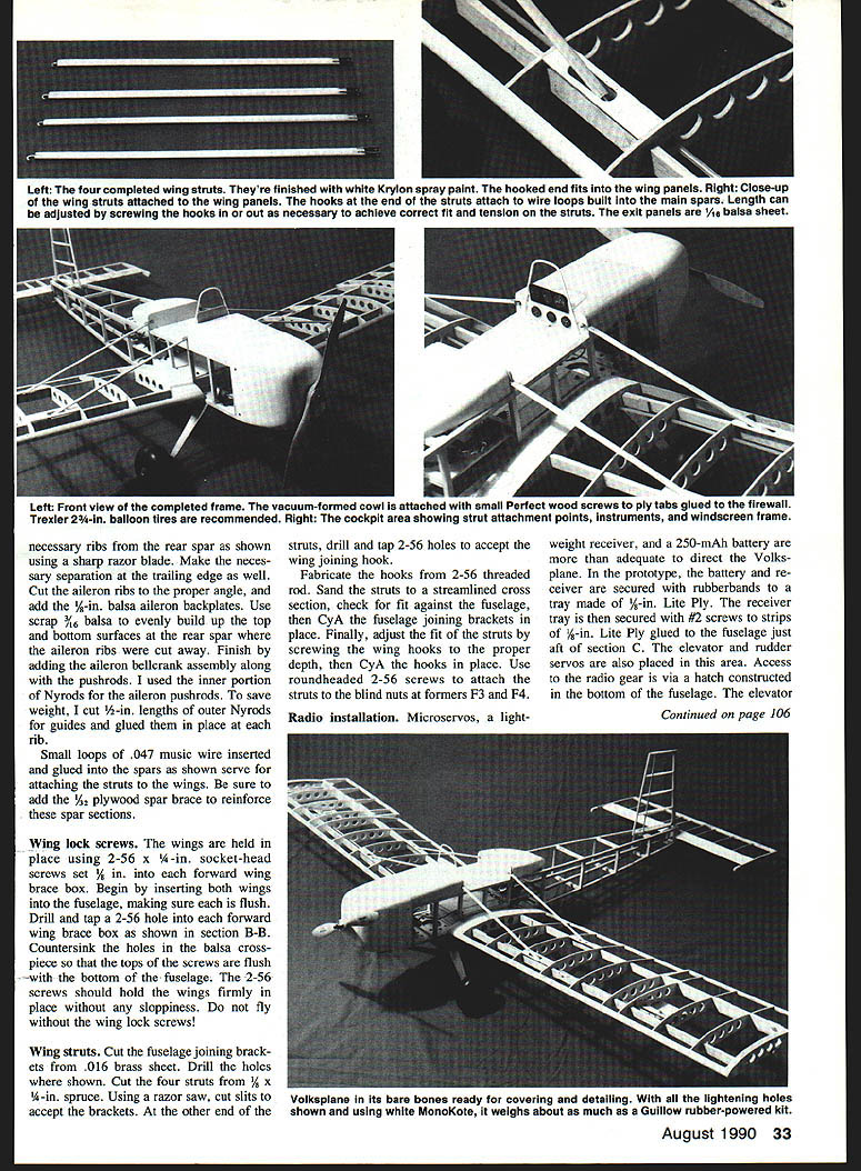
Wing struts
- Cut fuselage joining brackets from .016‑in. brass sheet and drill holes as shown.
- Cut four struts from 3/8 x 1/4‑in. spruce. Cut slits to accept brackets and drill/tap 2‑56 holes at the opposite end for the wing joining hooks.
- Fabricate hooks from 2‑56 threaded rod. Sand struts to a streamlined cross section and check fit against the fuselage.
- CyA the fuselage joining brackets in place. Adjust strut fit by screwing wing hooks to the proper depth and CyA the hooks in place.
- Use round‑head 2‑56 screws to attach struts to the blind nuts at formers F3 and F4.
Radio installation
- Microservos, a lightweight receiver, and a 250‑mAh battery are adequate for control.
- In the prototype, the receiver and battery were secured with rubber bands to a 1/8‑in. lite‑ply tray, which is screwed with #2 screws to 1/8‑in. lite‑ply strips glued to the fuselage just aft of section C. Elevator and rudder servos are placed in this area. Access via a hatch in the fuselage bottom.
- Elevator and rudder pushrods are 1/4‑in. balsa and should be installed prior to covering.
- The aileron servo is mounted on the bottom of the battery floor aft of section B using servo mounting tape. Seal the balsa grain with thin CyA before applying the tape and provide a separate hatch for access.
- For aileron linkage, the aileron pushrod clevises overlap and attach to a single hole in the servo arm. Du‑Bro metal Kwik‑Links with one male arm removed allow the remaining female arm to be held in place by the overlapping male arm of the other clevis.
Covering and finishing
- The prototype used white MonoKote throughout. Cover the rudder before the fuselage.
- When covering the fuselage: cover the sides first, then the top. While the bottom is open, install the rudder, rudder post assembly, and rudder pushrod. Ensure the cotter pin is secure and the tiller arm is firmly in place, then cover the fuselage bottom.
- Paint the cowl, turtledeck, struts, and landing gear with Krylon gloss white spray.
- Wood trim: adhesive‑backed mahogany veneer was used for the side trim and given several coats of clear‑gloss polyurethane.
- Registration numbers and trim can be cut from MonoKote and ironed on. "Experimental" lettering on the cockpit sides can be done with adhesive‑backed clear type from lettering services.
Final assembly
- Attach windshield and cowl with Wilhold R/C 56 or similar adhesive.
- Complete the cockpit, attach main and tail landing gear, and install the stabilator.
- Secure the motor battery pack with adhesive‑backed Velcro. Coat the battery floor with CyA, attach one side of Velcro, then attach the mating side to the battery pack.
- Prepare for wing attachment: cut slits in the turtledeck and forward fuselage sheeting to accept wing struts. Carefully slide wing panels into the fuselage, routing struts and aileron pushrods into their slots. Connect clevises to the aileron servo arm, cinch down the access hatch, and check all linkages.
Prop recommendations:
- Start with a Rev‑Up 12 x 8 prop. This is slightly larger than the Astro Flight recommended 11 x 7 for a geared .05, but the motor can handle it and the extra thrust improves performance.
Flying
- Balance at 25%–30% of the wing chord behind the leading edge. Adjust motor/battery fore/aft as needed.
- Check all fittings and control surface movements with the motor running. Set elevator travel initially to no more than 1/2 in. up/down for first flights.
- Launch into the wind with smooth throttle application. Expect to apply a little right rudder to counter P‑factor on takeoff.
- The Volksplane is not fast—use gentle climb‑outs and avoid aggressive maneuvers. Expect stable, scale‑like performance. Loops should be possible after a shallow dive; for rolls, consider a cobalt .15 for added power.
- Landings are graceful with some throttle modulation. Flying at two‑thirds throttle gives plenty of power for scale‑like performance. The model easily sustains eight‑ to ten‑minute flights.
- In competition at the San Luis Obispo Electrifest, this Volksplane took first place in Sport Scale—proof that it's a great electric project for those joining the quiet revolution.
Transcribed from original scans by AI. Minor OCR errors may remain.

