
The Waco
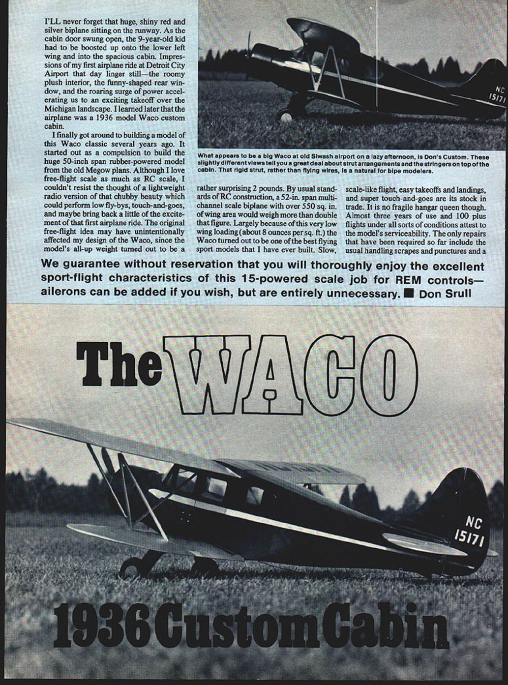
I'll never forget that huge, shiny red-and-silver biplane sitting on the runway. As the cabin door swung open, the 9-year-old kid had to be boosted up onto the lower left wing and into the spacious cabin. Impressions of my first airplane ride at Detroit City Airport that day linger still — the roomy plush interior, the funny-shaped rear window, and the roaring surge of power accelerating us to an exciting takeoff over the Michigan landscape. I learned later that the airplane was a 1936-model Waco Custom Cabin.
I finally got around to building a model of this Waco classic several years ago. It started out as a compulsion to build the huge 50-inch-span rubber-powered model from the old Megow plans. Although I love free-flight scale as much as RC scale, I couldn't resist the thought of a lightweight radio version of that chubby beauty which could perform low fly-bys, touch-and-goes, and maybe bring back a little of the excitement of that first airplane ride.
The original free-flight idea may have unintentionally affected my design of the Waco, since the model's all-up weight turned out to be a rather surprising 2 pounds. By usual standards of RC construction, a 52-in. span multi-channel scale biplane with over 550 sq. in. of wing area would weigh more than double that figure. Largely because of this very low wing loading (about 8 ounces per sq. ft.), the Waco turned out to be one of the best flying sport models that I have ever built. Slow, scale-like flight, easy takeoffs and landings, and super touch-and-goes are its stock and trade. It is no fragile hangar queen though. Almost three years of use and 100-plus flights under all sorts of conditions attest to the model's serviceability. The only repairs that have been required so far include the usual handling scrapes and punctures and a bent landing gear strut.
This .15-powered scale job for R/C has excellent sport-flight characteristics with rudder and elevator controls — ailerons can be added if you wish, but are entirely unnecessary. — Don Srull
Intent and design
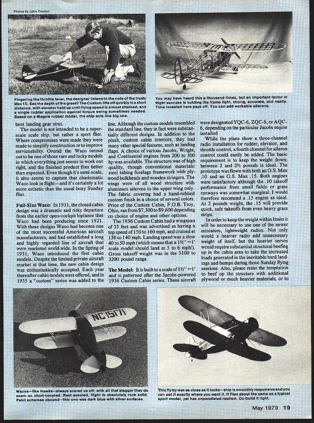
The model is not intended to be a super-scale ship, but rather a sport flier. Where compromises were made they were made to simplify construction or to improve serviceability. Overall the Waco turned out to be one of those rare and lucky models in which everything just seems to work out right, and the finished product flies better than expected. Even though it's semi-scale, it also seems to capture that charismatic Waco look in flight — and it's certainly a lot more aesthetic than the usual boxy Sunday flier.
Full-Size Waco
In 1931 the closed-cabin design was a dramatic and risky departure from the earlier open-cockpit biplanes that Waco had been producing since 1921. With these designs, Waco became one of the most successful American aircraft manufacturers, and had established a long and highly regarded line of aircraft that were marketed worldwide. In the spring of 1931 Waco introduced the first cabin models. Despite the limited private aircraft market at that time, the new cabin design was enthusiastically accepted. Each year thereafter cabin models were offered, and in 1935 a "Custom" series was added to the line.
Although the custom models resembled the standard line, they in fact were substantially different designs. In addition to plush, custom cabin interiors, they had many other special features, such as landing flaps. A choice of various Jacobs, Wright, and Continental engines from 200 to 300 hp was available. The structure was of high quality, though built of conventional materials: steel-tube fuselage framework with plywood bulkheads and wooden stringers. The wings were of all-wood structure with aluminum ailerons in the upper wing only. The fabric covering had a hand-rubbed custom finish in a choice of several colors. Price of the Custom Cabin, F.O.B. Troy, Ohio, ran from $7,300 to $9,600 depending on choice of engine and other options.
The 1936 Custom Cabin had a wingspan of 35 feet and was advertised as having a top speed of 150 to 160 mph, and cruising at 130 to 140 mph. Landing speed was a slow 40 to 50 mph (which means that a 1 1/2" = 1' scale model should land at 5 to 6 mph). Gross takeoff weight was in the 3,100 to 3,200 pound range.
The Model
The model is built to a scale of 1 1/2" = 1' and is patterned after the Jacobs-powered 1936 Custom Cabin series. These aircraft were designated YQC-6, ZQC-6, or AQC-6, depending on the particular Jacobs engine installed.
While the plans show a three-channel radio installation for rudder, elevator, and throttle control, a fourth channel for aileron control could easily be added. The basic requirement is to keep the weight down; between 2 and 2 1/2 pounds is ideal. The prototype was flown with both an O.S. Max .10 and an O.S. Max .15. Both engines were satisfactory although the .10 takeoff performance from small fields or grass runways was somewhat marginal. I would therefore recommend a .15 engine as ideal. At 2 pounds weight, the .15 will provide quick, safe takeoffs from even heavy grass strips.
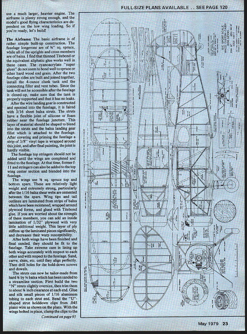
In order to keep the weight within limits it will be necessary to use one of the newer miniature, lightweight radios. Not only would a heavier radio add unnecessary weight of itself, but the heavier servos would require substantial structural beefing up in the cabin area to take the increased loads generated in the inevitable hard landings and bumps during those Sunday flying sessions. Also, please resist the temptation to beef up the structure with additional plywood or much heavier materials, or to use a much larger, heavier engine. The airframe is plenty strong enough, and the model's good flying characteristics are dependent on the low wing loading. So if you're ready, let's build!
The Airframe
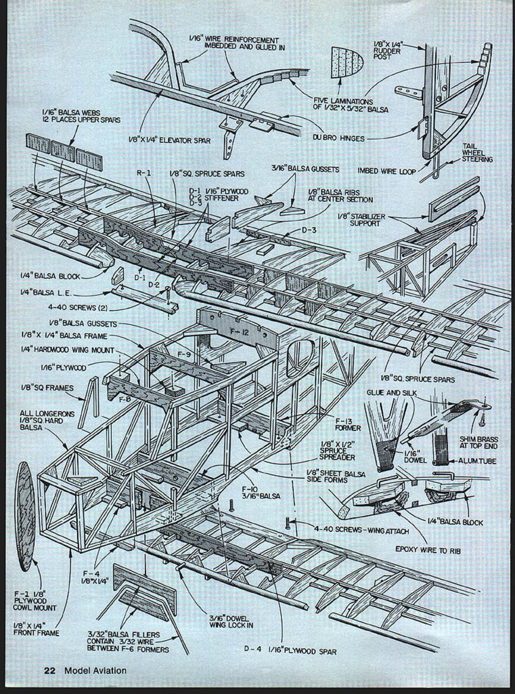
The basic airframe is of rather simple built-up construction. The fuselage longerons are 3/16" square spruce, while all of the uprights and cross members are of balsa. Thinned Titebond (or equivalent aliphatic glue) works well; cyanoacrylate "super glues" do not seem to bond well to spruce or other hard-wood end grain.
After the two fuselage sides are built and joined together, install the 4-ounce clunk tank and the connecting filler and vent tubes. Since the tank will not be accessible after the fuselage is closed up, make sure that the tank is properly supported and that it has no leaks.
After the wire landing gear is constructed and epoxied into the fuselage, it is faired with 3/16" sheet balsa struts. The struts have a flexible joint of silicone or foam rubber near the fuselage juncture. This layer of material should be shaped to blend into the struts and the balsa landing gear fillet which is attached to the fuselage. After covering and priming the fuselage a strip of 3/8" vinyl tape is wrapped around this joint; after final painting the joint is hardly visible.
The fuselage top stringers should not be added until the wings are completed and fitted to the fuselage. At that time, former F-11 and stringers can also be added to the top wing center section and blended into the fuselage.
The wings use 1/4" square spruce top and bottom spars. These are relatively lightweight and extremely strong, particularly after the 1/16" balsa shear webs are cemented between the spars. Wing tips and tail outlines are laminated from strips of balsa which have been moistened, wrapped around plywood forms, and glued with Titebond. If you are worried about the strength of these members, you can add an inside lamination of 1/32" plywood with very little additional weight. This layer of ply stiffens up the laminated pieces significantly and decreases their warp susceptibility.
After both wings have been finished and final-sanded, fit them to the fuselage. Take extreme care in lining up both wings accurately with respect to each other and with respect to the fuselage. Sand, carve, shim, etc., until they align perfectly. Then drill holes for the hold-down screws and dowels.
The struts can now be tailor-made from hard 3/16" x 1/4" balsa which has been sanded to a streamlined section. First build the two "N" struts slightly oversize, then trim them to about 1/16" clearance at each end. Glue and silk small pieces of 1/16" aluminum tubing to each strut end. Bend the "U"-shaped strut hold-down clips from .045 piano wire as shown on the plans. With the wings bolted in place, clamp the clips to the appropriate ribs (clothes pins work well for this), and slip the "N" struts into place. Move the clips around until a nice fit is obtained and spot-glue the clips with a small dab of epoxy. When the epoxy sets, remove the struts and secure the clips with plenty of epoxy and 1/8" balsa rib scabs.
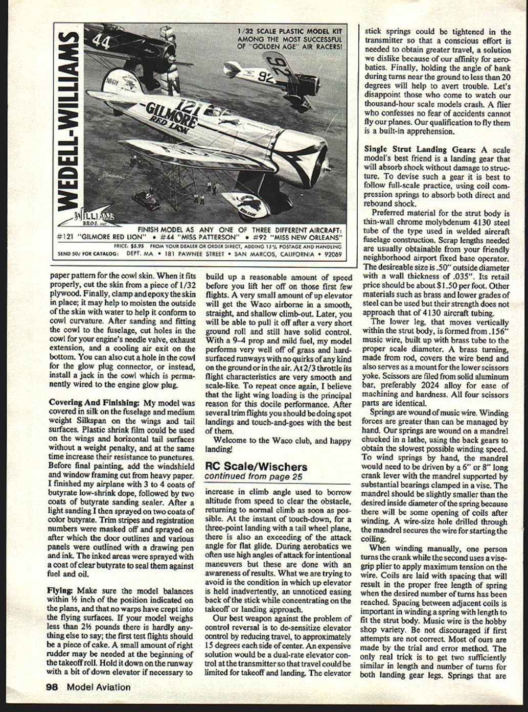
The cowl shown on the plans is simple, light and strong. First build the balsa drumlike frame. Sand the outside surface smooth and to a perfect circle. Next, cut a heavy paper pattern for the cowl skin. When it fits properly, cut the skin from a piece of 1/32" plywood. Finally, clamp and epoxy the skin in place; it may help to moisten the outside of the skin with water to help it conform to cowl curvature. After sanding and fitting the cowl to the fuselage, cut holes in the cowl for your engine's needle valve, exhaust extension, and a cooling air exit on the bottom. You can also cut a hole in the cowl for the glow-plug connector, or instead install a jack in the cowl which is permanently wired to the engine glow plug.
Parts and construction details
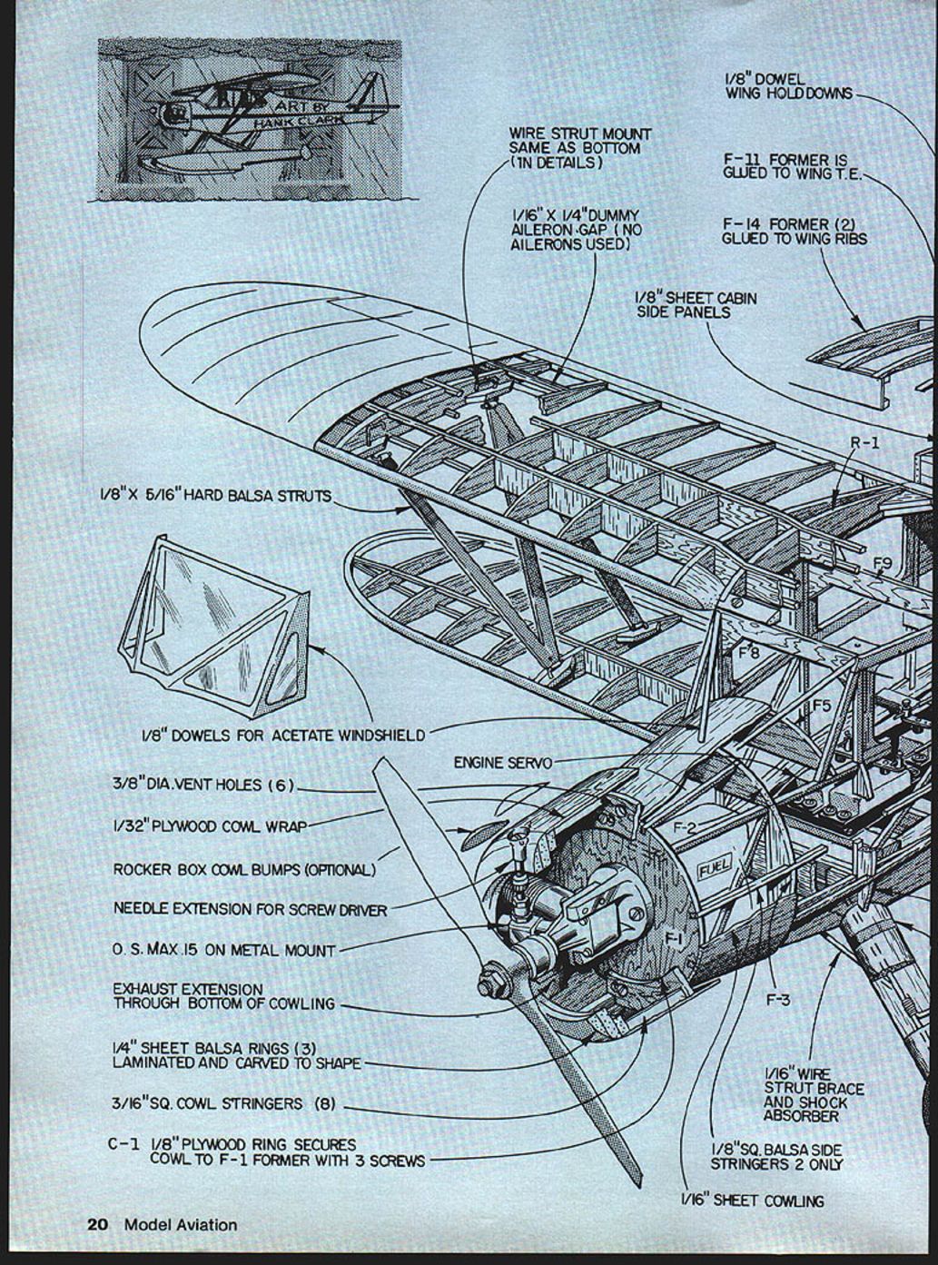
- 1/8" dowel wing hold-downs
- Wire strut mount same as bottom (see plans)
- 1/16" x 1/4" dummy aileron gap (no ailerons used)
- F-11 former is glued to wing trailing edge
- F-14 former (2) glued to wing ribs
- 1/8" sheet cabin side panels
- R-1 (rib)
- 1/8" x 5/16" hard balsa struts
- 1/8" dowels for acetate windshield
- 3/8" diameter vent holes (6)
- 1/32" plywood cowl wrap
- Rocker box cowl bumps (optional)
- Needle extension for screwdriver
- O.S. Max .15 on metal mount (recommended)
- Exhaust extension through bottom of cowling
- 1/4" sheet balsa rings (3) laminated and carved to shape
- 3/16" square cowl stringers (8)
- C-1 1/8" plywood ring secures cowl to F-1 former with 3 screws
- Engine servo
- Formers: F-2, F-3, F-5, F-7, F-8, F-9, F-12, F-14
- 1/16" wire strut brace and shock absorber
- 1/8" square balsa side stringers (2 only)
- 1/16" sheet cowling
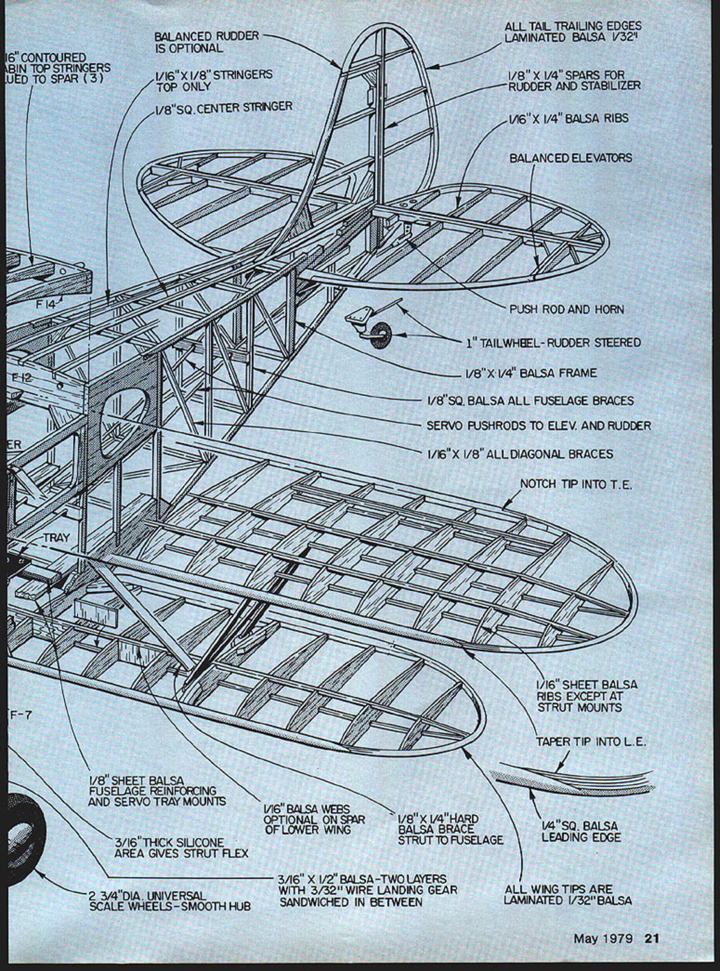
- 3/16" contoured cabin top stringers glued to spar (3)
- Balanced rudder is optional
- 1/16" x 1/8" stringers (top only)
- 1/8" square center stringer
- All tail trailing edges laminated balsa 1/32"
- 1/8" x 1/4" spars for rudder and stabilizer
- 1/16" x 1/4" balsa ribs
- Balanced elevators (recommended)
- Pushrod and horn
- 1" tailwheel — rudder-steered
- 1/8" x 1/4" balsa frame
- 1/8" square balsa for all fuselage braces
- Servo pushrods to elevator and rudder
- 1/16" x 1/8" all diagonal braces
- Notch tip into trailing edge where indicated
- 1/16" sheet balsa ribs except at strut mounts
- Taper tip into leading edge
- 1/4" square balsa leading edge
- 1/8" sheet balsa fuselage reinforcing and servo tray mounts
- 1/16" balsa webs optional on spar of lower wing
- 1/8" x 1/4" hard balsa brace strut to fuselage
- 3/16" thick silicone area gives strut flex
- 3/16" x 1/2" balsa — two layers with 3/32" wire landing gear sandwiched in between
- 2 3/4" diameter universal scale wheels — smooth hub
- All wing tips are laminated 1/32" balsa
(Note: the plans and diagrams contain additional part callouts and figure references; refer to the supplied plans for exact shapes and locations.)
Covering and finishing
My model was covered in silk on the fuselage and medium-weight Silkspan on the wings and tail surfaces. Plastic shrink film could be used on the wings and horizontal tail surfaces without a weight penalty, and at the same time increase their resistance to punctures.
Before final painting, add the windshield and window framing cut from heavy paper. I finished my airplane with 3 to 4 coats of butyrate low-shrink dope, followed by two coats of butyrate sanding sealer. After a light sanding I sprayed on two coats of color butyrate. Trim stripes and registration numbers were masked off and sprayed on; after that the door outlines and various panels were inked with a drawing pen. The inked areas were sprayed with a coat of clear butyrate to seal them against fuel and oil.
Flying
Make sure the model balances within 1/2 inch of the position indicated on the plans, and that no warps have crept into the flying surfaces. If your model weighs less than 2-1/2 pounds there is hardly anything else to say; the first test flights should be a piece of cake.
A small amount of right rudder may be needed at the beginning of the takeoff roll. Hold it down on the runway with a bit of down elevator if necessary to build up a reasonable amount of speed before you lift her off on those first few flights. A very small amount of up elevator will get the Waco airborne in a smooth, straight, and shallow climb-out. Later, you will be able to pull it off after a very short ground roll and still have solid control.
With a .09–4 prop and mild fuel, my model performs very well off of grass and hard-surfaced runways with no quirks of any kind on the ground or in the air. At two-thirds throttle its flight characteristics are very smooth and scale-like. To repeat once again, the light wing loading is the principal reason for this docile performance. After several trim flights you should be doing spot landings and touch-and-goes with the best of them.
Welcome to the Waco club, and happy landing!
Transcribed from original scans by AI. Minor OCR errors may remain.

