
WACO UPF-7: A Biplane From the Golden Age
Roy Day
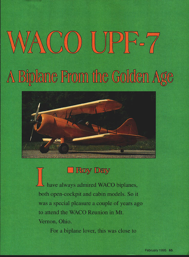
I have always admired WACO biplanes, both open-cockpit and cabin models. A couple of years ago I attended the WACO Reunion in Mt. Vernon, Ohio. For a biplane lover this was close to heaven: about 40 beautifully restored WACOs were there, from the 1927 WACO 10 to the 1942 UPF-7. After taking a flight in one of the UPF-7s, I decided to design and build a model.
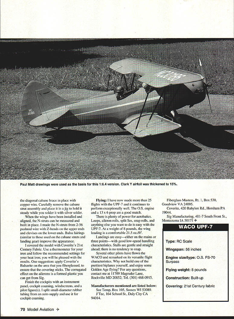
I used Paul Matt's three-view drawings and designed a 1:6.4 scale model. I used the Clark Y airfoil of the full-scale airplane, thickened from 12% to 15%. After many interruptions I completed the airplane about a year after starting the design and took it to our grass flying field for test flights.
During taxi tests it was hard to keep from overcontrolling the model, so I went back to the shop and reduced the sensitivity of the tailwheel to half that of the rudder deflection. The WACO steered much better on the ground and was ready for first flight. Flying buddy Ron Rozzonte made the first takeoff. The UPF-7 came up on its mains quickly and, with a little right rudder, the big vertical tail held it arrow-straight down the runway. Liftoff occurred at about 3/4 throttle with the O.S. 70 Surpass four-stroke.
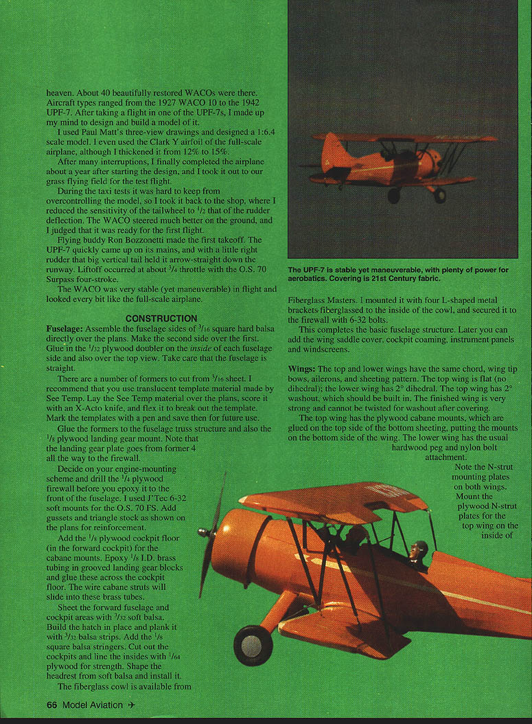
The model is very stable yet maneuverable and looks every bit like the full-scale airplane.
CONSTRUCTION
Fuselage
Assemble the fuselage sides of 3/16" square hard balsa directly over the plans. Make the second side over the first. Glue in the 1/32" plywood doubler on the inside of each fuselage side and over the top view. Take care that the fuselage remains straight.
Cut formers from 3/16" sheet. I recommend using translucent template material such as See-Temp: lay the See-Temp over the plans, score with an X-Acto knife, flex to break out the template, mark with a pen, and save for future use.
Glue the formers to the fuselage truss structure and install the 1/8" plywood landing gear mount. Note that the landing gear plate runs from former 4 all the way to the firewall.
Decide on your engine-mounting scheme and drill the 1/4" plywood firewall before epoxying it to the front of the fuselage. I used J-Tec 6-32 soft mounts for the O.S. 70 FS. Add gussets and triangle stock as shown on the plans for reinforcement.
Add the 1/8" plywood cockpit floor (in the forward cockpit) for the cabane mounts. Epoxy 1/8" I.D. brass tubing in grooved landing gear blocks and glue these across the cockpit floor—the wire cabane struts will slide into these brass tubes.
Sheet the forward fuselage and cockpit areas with 1/32" soft balsa. Build the hatch in place and plank it with 1/32" balsa strips. Add 1/8" square balsa stringers. Cut out the cockpits and line the insides with 1/64" plywood for strength. Shape the headrest from soft balsa and install it.
The fiberglass cowl is available from Fiberglass Masters. I mounted it with four L-shaped metal brackets fiberglassed to the inside of the cowl and secured it to the firewall with 6-32 bolts.
This completes the basic fuselage structure. Later you can add the wing saddle cover, cockpit coaming, instrument panels and windscreens.
Wings
The top and lower wings have the same chord, wing tip bows, ailerons, and sheeting pattern. The top wing is flat (no dihedral); the lower wing has 2° dihedral. The top wing has 2° washout, which should be built in—the finished wing is very strong and cannot be twisted for washout after covering.
The top wing has the plywood cabane mounts glued on the top side of the bottom sheeting, putting the mounts on the bottom side of the wing. The lower wing uses the usual hardwood peg and nylon bolt attachment.
Note the N-strut mounting plates on both wings. Mount the plywood N-strut plates for the top wing on the inside of the top sheeting.
Before you sheet the top surface, install the aileron pushrods. I used the flexible Nyrod type, but any pushrod type of your choice will work.
Dampen the top trailing-edge sheeting so it can be formed correctly around the wing cutout. After the top sheeting is on, add the cap strips top and bottom.
Fiberglass the center section of both wings with one-ounce cloth and laminating epoxy.
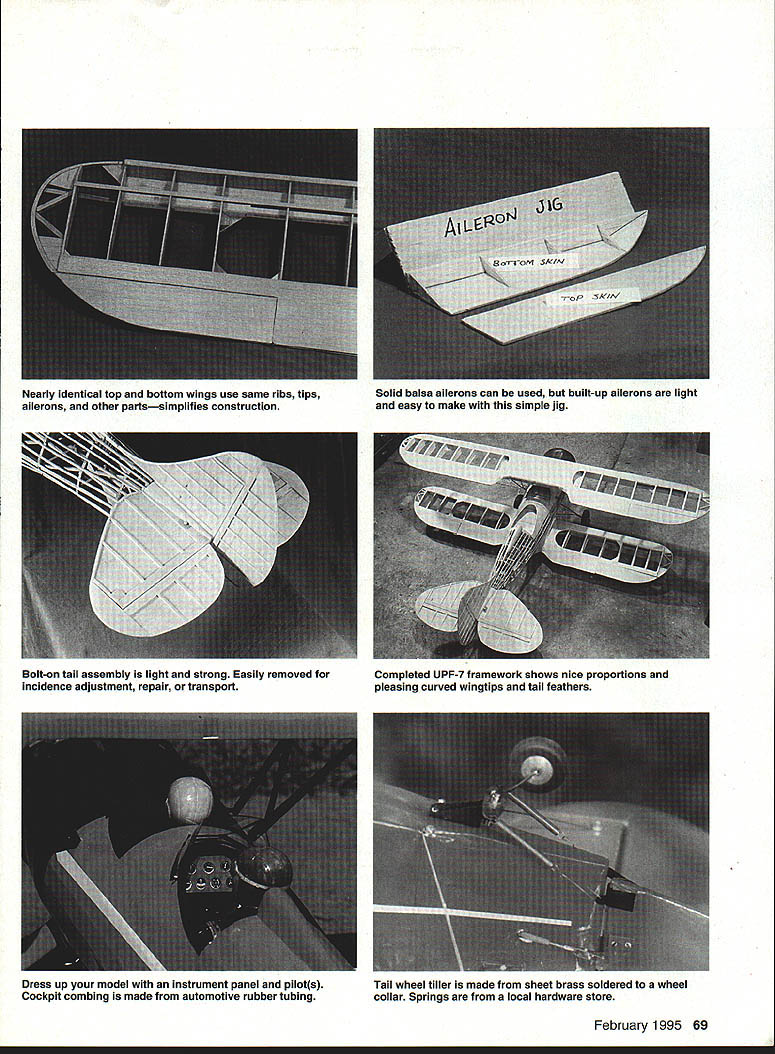
Nearly identical top and bottom wings use the same ribs, tips, ailerons, and other parts—this simplifies construction.
Ailerons
The four ailerons are built next. I prefer built-up ailerons because of their light weight, but solid lightweight balsa (with lightening holes) can be used. Built-up ailerons are easy to make with a simple jig; the patterns for the top and bottom 1/16" skins are shown on the plan. Install 1/8" plywood mounts for the aileron horn and the connecting pushrod.
The corrugated effect on the ailerons is a formed plastic available from Sig.
N-struts and Cabane
When the wings are installed and aligned, measure and build the N-struts in place. I made the N-struts from 2-56 pushrod wire with Z-bends on the upper ends and clevises on the lower ends. Balsa fairings (similar to those used on the cabane struts and landing gear) improve the appearance.
The diagonal cabane brace is assembled with copper wire. Carefully remove the cabane strut assembly and place it in a jig to hold it steady while you solder it with silver solder.
Tail Structure
The horizontal and vertical tails use a 3/32" balsa sheet core. Add 1/8" square false ribs on both sides to form a simple, lightweight, strong structure, well suited to the curved tail surfaces. Doublers of cross-laminated 3/32" balsa provide necessary stiffness and edge protection. See-Temp material is useful to cut out the entire sheet core for the vertical and horizontal tails at one time. Sand the false ribs top and bottom to give the airfoil shape.
As with the wings, use your preferred covering-material hinges—other hinge types will work as well. I prefer bolt-on tail surfaces: inset a plywood tongue in the bottom stab doubler and use two 6-32 nylon bolts to fasten the assembly to the fuselage. Shape blocks of light balsa to support the vertical tail and fair the stab into the fuselage at former 10A. A tail brace wire of .032" music wire adds a lot of strength.
ASSEMBLY AND FINISHING
It is good practice to install radio equipment before covering. Place servos as far forward as practical; the receiver and battery go alongside the fuel tank. With the O.S. 70 Surpass FS you will likely need to add some weight to balance the model. The center of gravity (CG) is indicated on the plan.
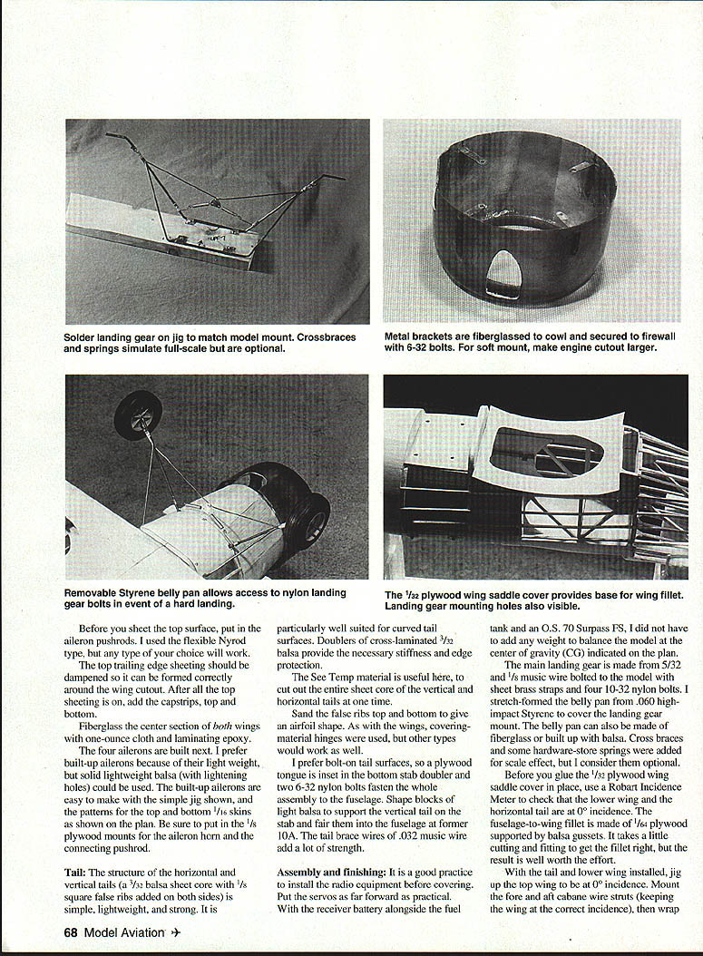
The main landing gear is made from 5/32" and 1/8" music wire bolted to sheet brass straps with four 10-32 nylon bolts. I stretch-formed the belly pan from .060" high-impact styrene to cover the landing gear mount; the belly pan can also be made of fiberglass or built up with balsa. Built-up balsa crossbraces and some hardware-store springs can be added for scale effect but are optional.
Before gluing the 1/32" plywood wing saddle cover in place, use a Robart Incidence Meter to check that the lower wing and the horizontal tail are at 0° incidence. The fuselage-to-wing fillet is made from 1/64" plywood supported by balsa gussets—cutting and fitting the fillet carefully is worth the effort.
With the tail and lower wing installed, jig up the top wing at 0° incidence. Mount the fore and aft cabane wire struts, keeping the wing at the correct incidence. Wrap the landing-gear jig to match the model mount. Crossbraces and springs simulate full-scale details and are optional.
Metal brackets fiberglassed to the cowl secure it to the firewall with 6-32 bolts and soft mounts; make the engine cutout larger if necessary. A removable styrene belly pan allows access to the nylon landing-gear bolts in the event of a hard landing. The 1/32" plywood wing saddle cover provides the base for the wing fillet. Landing-gear mounting holes should be visible for alignment.
The bolt-on tail assembly is light, strong and easily removed for incidence adjustment, repair, or transport. Dress up the model with an instrument panel and pilot figure(s). Cockpit coaming can be made from split automotive rubber tubing.
The tailwheel tiller is made from sheet brass with a soldered wheel collar. Springs are from the local hardware store.
COVERING AND FINISHING DETAILS
I covered the model with Coverite's 21st Century Fabric. Use a thermometer for your heat iron and follow the recommended settings—results are very pleasing. Apply Coverite's Balsarite on the area you fiberglassed to ensure the covering sticks.
Finish the cockpits with instrument panels, windscreens, and pilot figures. Cockpit coaming can be made from split small-diameter rubber tubing from an auto supply.
FLYING
I have made more than 25 flights with the UPF-7 and it continues to perform exceptionally well. The O.S. engine with a 13 x 6 prop is a good match; there is plenty of power for aerobatics. Loops, aileron rolls, split S's, snap rolls and other maneuvers are easy. At a flying weight of 8 pounds, the wing loading is a comfortable 21.5 oz./ft.².
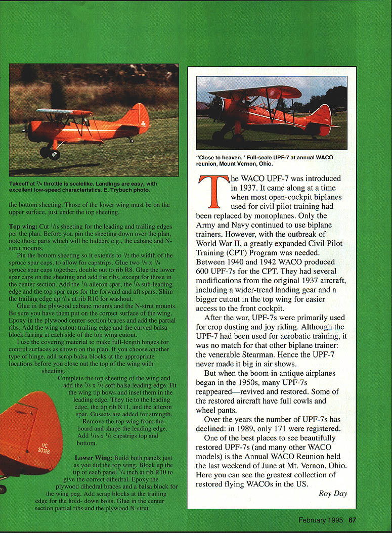
Landings are easy—either on the mains or three-point—with good low-speed handling. Stalls are gentle and straight ahead with no tendency to snap. Several other pilots have flown the WACO and remarked on its versatile flight characteristics.
Why not build one of the prettiest biplanes yourself and enjoy some Golden Age flying? For questions, contact: 11709 Magruder Lane, Rockville MD 20852; Tel. (301) 468-0915.
HISTORY
The WACO UPF-7 was introduced in 1937. It arrived when most open-cockpit biplanes used for civil pilot training were being replaced by monoplanes; only the Army and Navy retained biplane trainers. With the outbreak of World War II and a greatly expanded Civil Pilot Training (CPT) Program, WACO produced 600 UPF-7s between 1940 and 1942. Modifications from the original 1937 aircraft included a wider-tread landing gear and a larger cutout in the top wing for easier access to the front cockpit.
After the war UPF-7s were primarily used for crop dusting and joy riding. Although used for aerobatic training, the UPF-7 was no match for the Stearman and never became a major air-show performer. When the antique airplane boom began in the 1950s many UPF-7s were revived and restored; some restored aircraft have full cowlings and wheel pants.
Over the years the number of UPF-7s has declined: in 1989 only 171 were registered.
One of the best places to see beautifully restored UPF-7s and many other WACO models is the Annual WACO Reunion held the last weekend of June at Mt. Vernon, Ohio—the greatest collection of restored flying WACOs in the U.S.
MANUFACTURERS / SUPPLIERS
- See-Temp, Box 105, Sussex WI 53089
- J-Tec, 164 School St., Daly City CA 94014
- Fiberglass Masters, Rt. 1, Box 530, Goodview VA 24095
- Conway, 420 Babylon Rd., Horsham PA 19044
- Sig Manufacturing, 401-7 South Front St., Montezuma IA 50171
WACO UPF-7 (MODEL) SPECIFICATIONS
- Type: RC Scale
- Wingspan: 56 inches
- Engine size/type: O.S. FS-70 Surpass
- Flying weight: 8 pounds
- Construction: Built-up
- Covering: 21st Century Fabric
Transcribed from original scans by AI. Minor OCR errors may remain.

