
Waltzing Matilda
J. P. Van Leuven
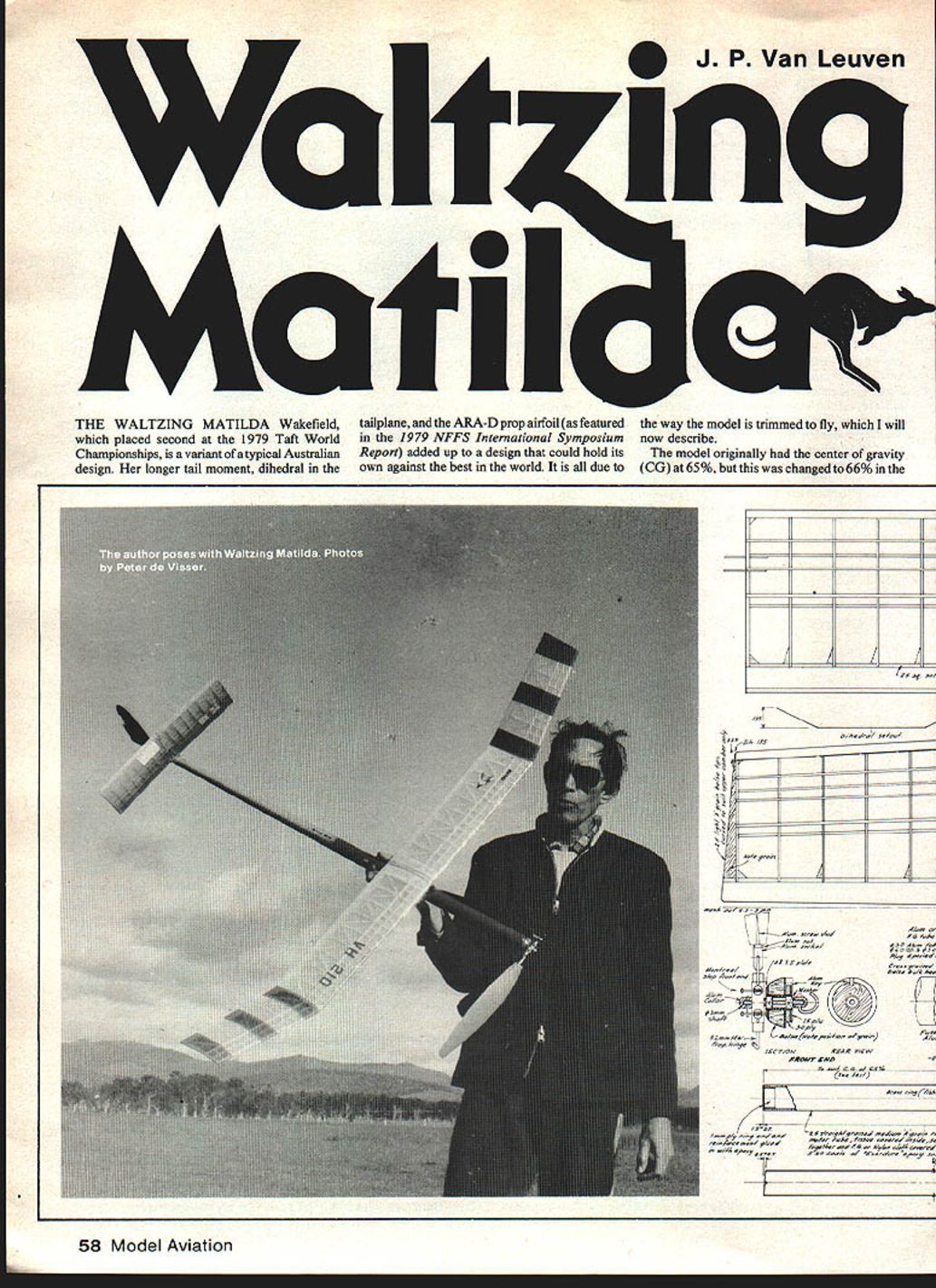
THE WALTZING MATILDA Wakefield, which placed second at the 1979 Taft World Championships, is a variant of a typical Australian design. Her longer tail moment, dihedral in the tailplane, and the ARA-D prop airfoil (as featured in the 1979 NFFS International Symposium Report) added up to a design that could hold its own against the best in the world. It is all due to the way the model is trimmed to fly, which I will now describe.
The model originally had the center of gravity (CG) at 65%, but this was changed to 66% in the field by moving the strapped-on weight; an improved glide was obtained.
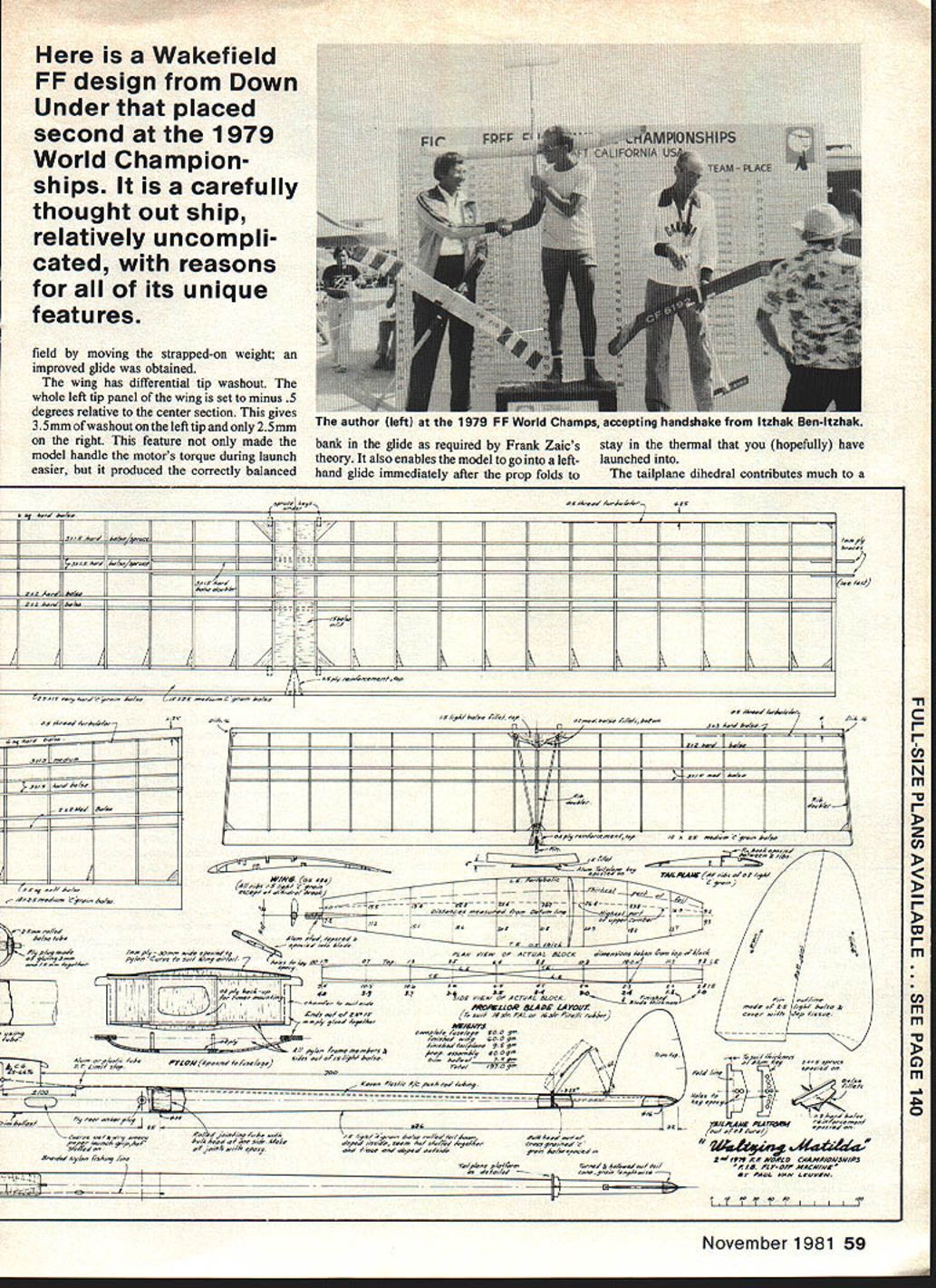
The wing has differential tip washout. The whole left tip panel of the wing is set to minus 0.5 degrees relative to the center section. This gives 3.5 mm of washout on the left tip and only 2.5 mm on the right. This feature not only made the model handle the motor's torque during launch more easily, but it produced the correctly balanced bank in the glide as required by Frank Zaic's theory. It also enables the model to go into a left-hand glide immediately after the prop folds to stay in the thermal that you (hopefully) have launched into.
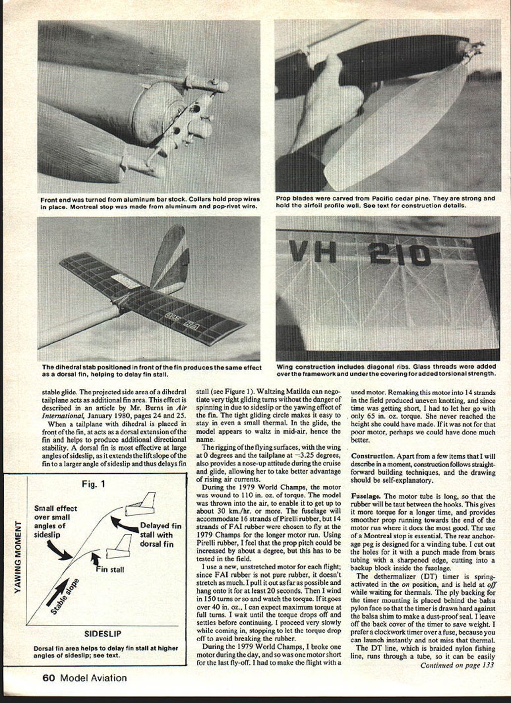
The tailplane dihedral contributes much to a stable glide. The projected side area of a dihedral tailplane acts as additional fin area, as described by Mr. Burns, Air International, January 1980, pages 24–25. A tailplane dihedral placed in front of the fin acts as a dorsal extension; the fin helps produce additional directional stability. The dorsal fin is effective at large angles of sideslip — it extends the lift slope of the fin to larger angles of sideslip and thus delays fin stall (see Figure 1).
Waltzing Matilda can negotiate very tight gliding turns without danger of spinning due to the sideslip-yawing effect of the fin. The tight gliding circle makes it easy to stay in a small thermal. The model appears to waltz mid-air, hence the name.
Rigging flying surfaces:
- Wing: 0 degrees
- Tailplane: 3.25 degrees
This also provides a nose-up attitude during cruise glide, allowing the model to take better advantage of rising air currents.
During the 1979 World Champs the motor was wound to 110 in. oz. torque. The model, thrown into the air, would get up to about 30 km/hr. The fuselage will accommodate 16 strands of Pirelli rubber; 14 strands of FAI rubber were chosen to fly the 1979 Champs for a longer motor run. Using Pirelli rubber I feel the prop pitch could be increased about 1 degree. I have tested in the field with a new unstretched motor; since FAI rubber (pure rubber) doesn't stretch much, pull out as far as possible.
When winding, hang on at least 20 seconds; when wound to 150 turns, as the torque goes over 40 in. oz. you can expect maximum torque. At full turns wait until the torque drops off and settles before continuing. Proceed very slowly when coming to a stop; let the torque drop off to avoid breaking the rubber.
During the 1979 World Champs I broke a motor during the day. The motor was short for the last fly-off; to make the flight I used that motor. Remaking a 14-strand motor in the field produced uneven knotting; since time was getting short I let go at 65 in. oz. torque and never reached the height I could have. Perhaps I could have done much better.
Construction
Apart from a few items I will describe in a moment, construction follows straightforward building techniques, and the drawing should be self-explanatory.
Fuselage
The motor tube is long, so that the rubber will be between the hooks. This gives more torque for a longer time, and provides smoother prop running towards the end of the motor run where it does the most good. The use of a Montreal stop is essential. The rear anchorage peg is designed for a winding tube. I cut out the holes for it with a punch made from brass tubing, sharpened at the end, and cut into the balsa to leave a neat fit.
The dethermalizer (DT) timer is spring-activated in the on position, and is held at off while waiting for thermals. The ply backing for the timer mounting is placed behind the balsa pylon face so that the timer is drawn hard against the fuselage to make a dust-proof seal. I leave the DT in the off position for takeoff, so it can be wound in the hand. The DT line, which is braided nylon fishing line, runs through a tube, so it can be easily replaced if necessary. I figured in a 40 mm stretch in the line to pull the tailplane hard down and ensure alignment.
The pylon is the last glued piece, and is set in place with the model completely assembled to obtain the correct CG location.
Propeller and front end
The propeller requires care in carving. Use light C-grain balsa and cover with light glass or nylon cloth. The thickness shown on the drawing is the finished thickness, so the bare wood (before covering and finishing) should be 0.3–0.4 mm thinner than that figure.
Use at least three coats of epoxy, and sand smooth with wet-or-dry sandpaper between coats to achieve a glass-smooth finish. Note that the ARA-D airfoil section has its thickest part at approximately 22–24%, and that the leading edge must be parabolic in shape. This airfoil not only gives more thrust, but also produces better traction power in the cruise mode, where others tend to fail. Check frequently with calipers to be certain that both blades are exactly the same; also, make certain that they weigh the same.
I used a dural stud to connect the prop to the hinge, so that it could be adjusted to the required pitch for the best prop/rubber combination. I found that 31 degrees at 70% from the hub is best for 14 strands of FAI rubber. One needs to fabricate some sort of prop pitch gauge to check the blades in the field.
The nose block is hard balsa turned with a drill, and the ply faces are epoxied on later. If you use plenty of dope between stages of turning and sanding, the balsa will not split. Aluminum round bar stock is used for the Montreal stop. The ends are turned down, and holes are drilled to suit. A groove on one side locates the pivot wires, which are retained by a collar drawn over the ends. One could also use nylon thread and epoxy to bind the pivot wires. The stop pins are made from "pop" rivet wire; they have a groove filed in to locate an M.W. circlip that holds the springs in place.
Flying surfaces
It is best to trace the wing tip on tracing paper and build the wing tip on it, then reverse it for the other one. The tip construction is a "poor man's Hoerner tip;" it is light and strong. All surfaces are covered with light Modelspan and are doped with 50/50 three times. After trimming, seal all surfaces with one coat of polyurethane varnish.
Trimming After the normal incidence adjustments, one should make a series of 1½-minute test flights on approximately three-fourths of full turns to adjust the glide. At 66% CG, the gliding turns should take at least 18 to 20 seconds to complete, and should be about 75 feet in diameter. If she loses height too quickly, open out the turn or shim up the trailing edge of the tailplane.
Constantly check the wing and tailplane seating location, and keep an eye out for warps. Use a shifting weight to arrive at the best CG location in the glide. She should glide with a distinct bank and with the nose up. Carry out these tests often; no two flights will be in the same weather conditions, even on the same day.
Finally, try maximum power flights of one minute duration to get the climb right. Adjust down and side thrust so that the climb is similar each time; she should make 2½ turns on the way up. My model was trimmed out so fine that I never worried (or even looked), providing I had gotten 110 in. oz. of torque.
SAFE FLYING IS NO ACCIDENT
Launch checklist
Make a habit of going over this checklist before each release (remember Murphy's law!):
- Note that the nose plug is properly fitted.
- The DT line is OK and properly hooked up.
- The DT timer is functioning and set to the proper time.
- The wing and tailplane are properly seated.
- The trim tab and warps are the same as you had before.
To ensure success, one can leave nothing to chance. Failure is only one's own mistake; that's why I prefer a simple Wakefield that "flies itself." Happy flying.
Transcribed from original scans by AI. Minor OCR errors may remain.

