
Watts Up
By Kenneth Marron
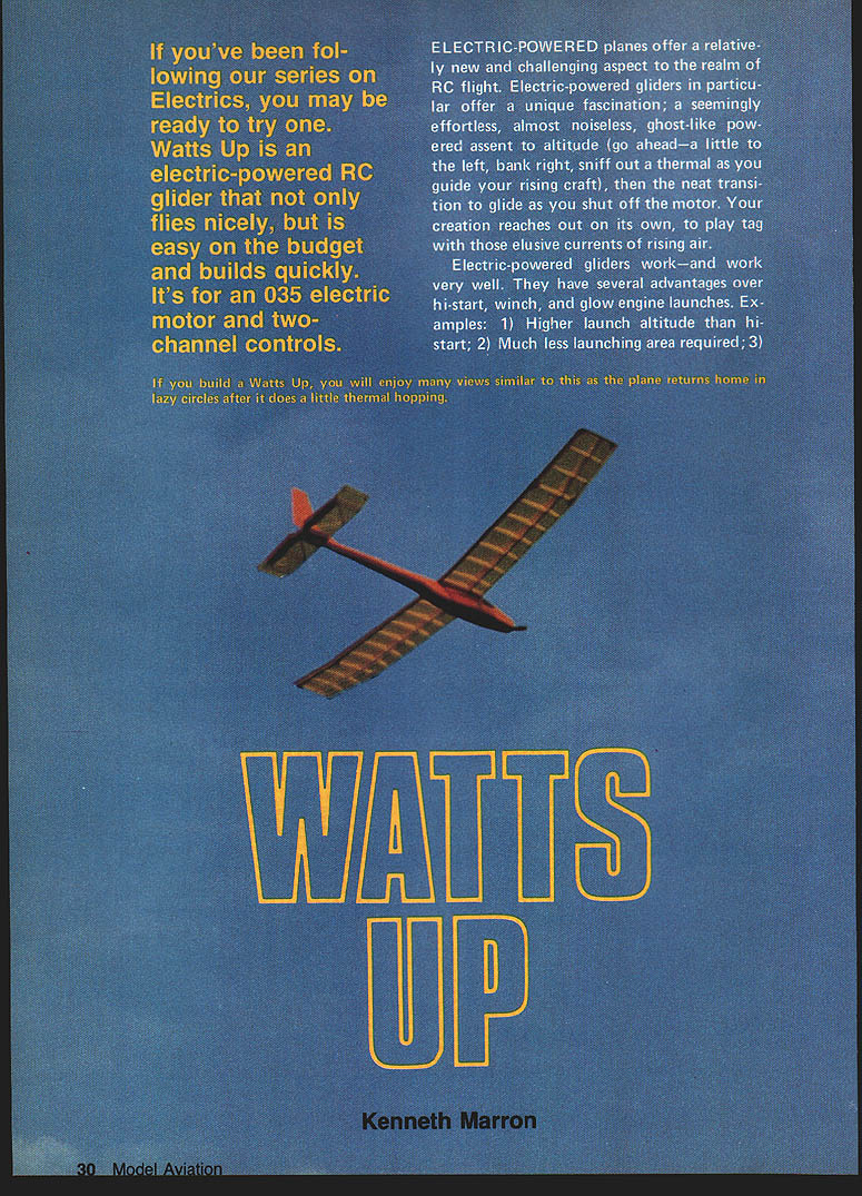
If you've been following our series on Electrics, you may be ready to try one. Watts Up is an electric-powered RC glider that not only flies nicely, but is easy on the budget and builds quickly. It's designed for a .035 electric motor and two-channel controls.
Electric-powered planes offer a relatively new and challenging aspect to the realm of RC flight. Electric-powered gliders in particular offer a unique fascination: a seemingly effortless, almost noiseless, ghost-like powered ascent to altitude (go ahead—a little to the left, bank right, sniff out a thermal as you guide your rising craft), then the neat transition to glide as you shut off the motor. Your creation reaches out on its own, to play tag with those elusive currents of rising air.
Electric-powered gliders work—and work very well. They have several advantages over hi-start, winch, and glow engine launches. Examples:
- Higher launch altitude than hi-start.
- Much less launching area required.
- Ideal for schoolyards and play areas (no mains or cords to trip over).
- No setup or retrieval of lines (great for evening flying).
- Can hunt for thermals while under power.
- No glow engine noise and mess.
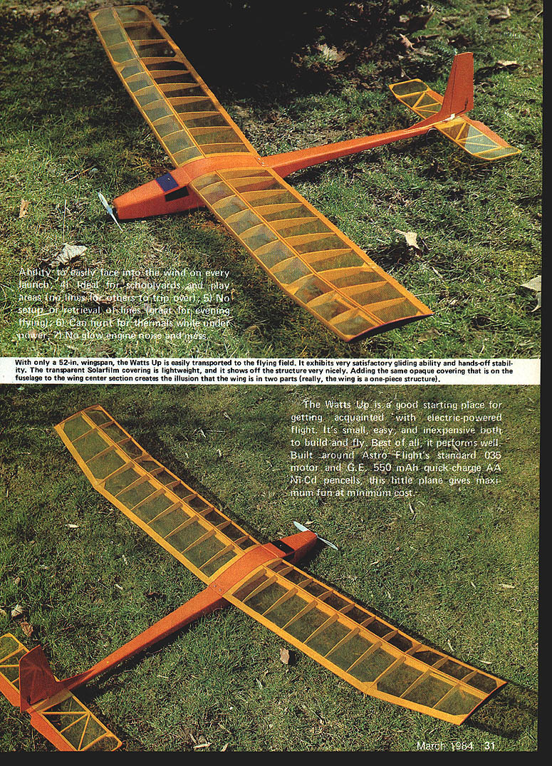
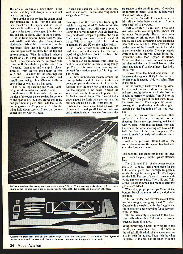
With only a 52 in. wingspan, the Watts Up is easily transported to the flying field. It exhibits very satisfactory gliding ability and hands-off stability. The transparent Solarfilm covering is lightweight, and it shows off the structure very nicely. Adding the same opaque covering that is on the fuselage to the wing center section creates the illusion that the wing is in two parts (really, the wing is a one-piece structure).
The Watts Up is a good starting place for getting acquainted with electric-powered flight. It's small, easy, and inexpensive both to build and fly. Best of all, it performs well. Built around Astro Flight's standard .035 motor and G.E. 550 mAh quick-charge AA Ni-Cd cells, this little plane gives maximum fun at minimum cost.
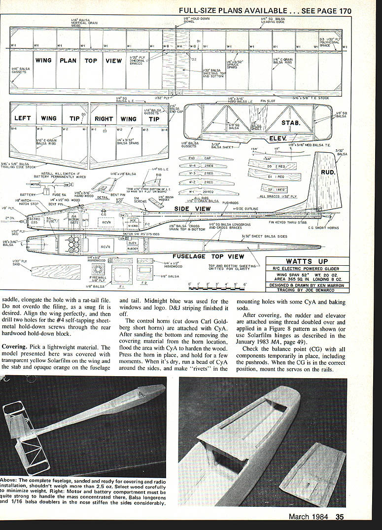
Three prototypes exist. The one presented in the plans and pictures has a span of 52 in., 365 sq. in. of area, and 20 oz. weight ready to fly. The weight breakdown: wing, covered, 3.5 oz.; fuselage with tail, covered, 3 oz.; motor and battery, 7.5 oz.; radio, 5 oz. with 100 mAh battery pack.
If you have not had much building experience, you should review the article on gluing techniques in the March 1983 MA before getting underway.
Wing construction
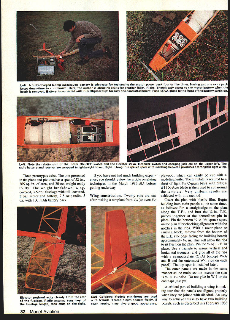
Twenty ribs are cut after making a template from 1/16 (or even 3/32) plywood, which can easily be cut with a modeling knife. The template is secured to a sheet of light 1/16 C-grain balsa with pins; a #11 X-Acto blade is then used to cut around the template. Very uniform results are achieved with this method.
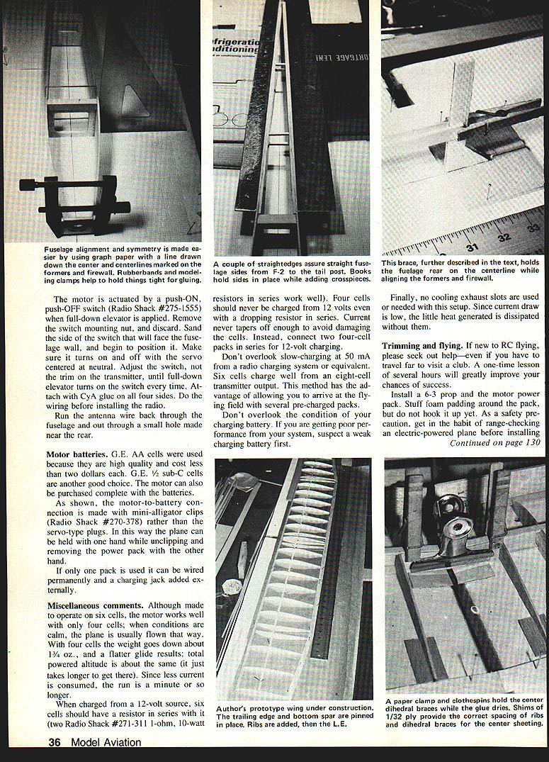
Cover the plan with plastic film. Begin building both main panels at the same time, as follows: pin a straightedge to the plan along the T.E., and butt the 5/8-in. T.E. pieces together at the centerline; pin in place. Pin the bottom 1/4 x 3/32 spruce spars on the plan after checking alignment and the notches in the ribs. With a razor plane or sanding block, remove from the bottom of the L.E. (the edge facing the building board) approximately 1/32 in. This will allow the ribs to sit flush on the plan. Pin the 1/4 sq. L.E. in place. Use a triangle to assure vertical and horizontal trueness, and glue all of the ribs with a cyanoacrylate (CyA) except W-A and B and the outermost W-1 ribs on each panel. The top spar is installed later.
The outer panels are made in the same manner as the main section, except the spar is 1/4 x 3/32 balsa. Do not glue in W-1 or the end caps just yet.
A critical part of building a wing is making sure that the panels are aligned properly when they are joined with dihedral. An easy way to achieve this is to have two building boards, such as described in a February 1983 MA article. Accurately hinge the middle; the wing will always want a slight twist angle. Prop up the boards so the center-panel spar bottoms are 1/2 in. above the table surface. Bevel the L.E. spars so the T.E. fits well when joined at the dihedral angle. Apply white glue to the mating edges and join the panels; pin in place. Glue the top spar. Cut a front dihedral brace from 1/8-in. ply and install it with white glue; clamp. Use clothespins to set up while cutting and fitting the rear brace.
Note: the 1/16-in. narrower spar depth allows the top and bottom sheeting to be installed. Place a 1/2-in. scrap spacer under the brace to check alignment; another 1/2-in. scrap should slip out flush with the top spar when correct. Trim as needed, glue and clamp in place. Trim the top and bottom ribs W-A and B to allow sheeting. Cut the ribs for the two-spar notches and install using shims. Glue W-A ribs and the other well-fitting wing parts.
Install 1/32-in. top sheeting and 1/16-in. vertical-grain shear webs next on the panels. Shape and sand the L.E. and wing tips. Add the end caps. The finished wing should weigh about 2.5 oz.
Fuselage
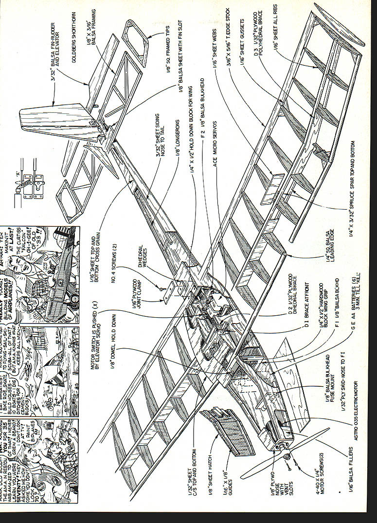
Cut the two sides from lightweight, straight-grained 3/32 balsa of similar density so that they will curve evenly. Clamp the halves together with clothespins, using cardboard scraps to protect the balsa from denting, and sand them to identical shape. With a triangle, mark the positions of formers F1 and F2 on the inside walls. Cut F1 and F2 from 1/8-in. stiff balsa, and mark their vertical centers. Cut the hardwood wing hold-down blocks, and bevel the L.E. block as per the plan.
A brace can be fashioned from scrap 1/16 or 1/8 balsa to hold the tail while lining things up on the base. The base is made about 3 in. sq. and notched for a vertical post 4 or 5 in. high and 1 in. wide.
Put three rubber bands loosely around the fuselage halves, and clip the tail to the temporary support with a clothespin. Line up the fuselage over the top view of the plan, and pin the support to the board. Spread the sides, and slide the formers into place. Test-fit the hardwood pieces. The forward hold-down should be flush with the top, and the rear one should be 1/16 in. in from the top.
When the formers are lined up over the plan—vertical and parallel to each other—and a triangle shows that the fuselage sides are square to the building board, CyA-glue the formers in place. Glue in the hardwood blocks with white glue.
Cut out the firewall. It's much easier to drill all the holes before cutting it from a large sheet of 1/8 plywood. Drill a center 7/16-in. dia. hole and 5/16-in. dia. motor mounting holes; check that the motor fits properly. The air inlet holes are formed by drilling two 1/4-in. dia. holes side-by-side and connecting and enlarging them with a rat-tail file. Draw a vertical line on the center of the firewall. Pull in the sides at the nose with a padded C-clamp. Apply white glue to the firewall edges; install between the sides, then tighten the clamp. Make sure that the centerline matches the plan and that the firewall has no side thrust and about 2° of downthrust. Let it dry thoroughly.
Remove from the board and install the longerons throughout. If CyA glue is used, no clamping is needed. Add 1/64 balsa fillers in the nose.
Put the fuselage back over the top view. Place a book on each side of the fuselage, and rest a straightedge on each; the fuselage should be perfectly straight from F-1 to the tail. Apply CyA glue at the tail joint. Install the cross braces. Then apply the 1/16-in. cross-grain top sheeting with white glue, stopping at the beginning of the stab location.
Install the pushrod outer sleeves. Then apply all the 1/16-in. cross-grain bottom sheeting. Finish the top sheeting and hatch with 1/32-in. balsa. Note that the hatch front and the rear of the nose sheeting are beveled to hold the front of the hatch in place. The catch is made from strips of hardwood and a bent pin.
Add a 1/32-in. ply skid. Round off all the corners to minimize the square box look and sand the fuselage smooth.
Tail section
The stabilizer is built in three pieces over the plan, but the tips are attached later.
The L.E. and T.E. of the center section are 1/8 x 1/8 balsa. Pick a hard piece for the L.E. and a piece soft enough to push a needle through for sewing on elevator hinges for the T.E. The rest of the stab is made with 1/8 sq. lightweight balsa. The L.E. and T.E. of the tips are trimmed and rounded after the gussets are added.
When dry, prop up the tips 1/2 in. at the bottom. Bevel the mating edges, and glue in position.
The fin, rudder, and elevator are cut from medium-weight, straight-grained 3/32 balsa. Cut a slot in the stabilizer for the fin; glue the fin in position after checking for squareness with the stab.
The tail assembly is attached to the fuselage with white glue. Take time to assure trueness from all angles.
Wing mounting
Check the wing fit in the saddle, and mark its center. Drill a hole in the wing L.E. dihedral brace to accommodate a 1/8-in. peg. Then slide the wing in place; if it does not sit flush with the saddle, elongate the hole with a rat-tail file. Do not overdo the filing, as a snug fit is desired. Align the wing perfectly, and then drill two holes for the #4 self-tapping sheet-metal hold-down screws through the rear hardwood hold-down block.
Covering. Pick a lightweight material. The model presented here was covered with transparent yellow Solarfilm on the wing and the stab and opaque orange on the fuselage and tail. Midnight blue was used for the windows and logo. D&J striping finished it off.
The control horns (cut down Carl Goldberg short horns) are attached with CyA. After sanding the bottom and removing the covering material from the horn location, flood the area with CyA to harden the wood. Press the horn in place, and hold for a few moments. When it's dry, run a bead of CyA around the sides, and make "rivets" in the mounting holes with some CyA and baking soda.
After covering, the rudder and elevator are attached using thread doubled over and applied in a Figure-8 pattern as shown (or use Solarfilm hinges as described in the January 1983 MA, page 49).
Check the balance point (CG) with all components temporarily in place, including the pushrods. When the CG is in the correct position, mount the servos on the rails.
The motor is actuated by a push-ON, push-OFF switch (Radio Shack #275-1555) when full-down elevator is applied. Remove the switch mounting nut, and discard. Sand the side of the switch that will face the fuselage wall, and begin to position it. Make sure it turns on and off with the servo centered at neutral. Adjust the switch, not the trim on the transmitter, until full-down elevator turns on the switch every time. Attach with CyA glue on all four sides. Do the wiring before installing the radio.
Run the antenna wire back through the fuselage and out through a small hole made near the rear.
Motor batteries. G.E. AA cells were used because they are high quality and cost less than two dollars each. G.E. 2/3-sub-C cells are another good choice. The motor can also be purchased complete with the batteries.
As shown, the motor-to-battery connection is made with mini-alligator clips (Radio Shack #270-378) rather than the servo-type plugs. In this way the plane can be held with one hand while unclipping and removing the power pack with the other hand.
If only one pack is used it can be wired permanently and a charging jack added externally.
Miscellaneous comments. Although made to operate on six cells, the motor works well with only four cells; when conditions are calm, the plane is usually flown that way. With four cells the weight goes down about 1-1/2 oz., and a flatter glide results; total powered altitude is about the same (it just takes longer to get there). Since less current is consumed, the run is a minute or so longer.
When charged from a 12-volt source, six cells should have a resistor in series with it (two Radio Shack #271-311 1-ohm, 10-watt resistors in series work well). Four cells should never be charged from 12 volts even with a dropping resistor in series. Current never tapers off enough to avoid damaging the cells. Instead, connect two four-cell packs in series for 12-volt charging.
Don't overlook slow-charging at 50 mA from a radio charging system or equivalent. Six cells charge well from an eight-cell transmitter output. This method has the advantage of allowing you to arrive at the flying field with several pre-charged packs.
Don't overlook the condition of your charging battery. If you are getting poor performance from your system, suspect a weak charging battery first.
Finally, no cooling exhaust slots are used or needed with this setup. Since current draw is low, the little heat generated is dissipated without them.
Trimming and flying
If new to RC flying, please seek out the help—even if you have to travel far to visit a club. A one-time lesson of several hours will greatly improve your chances of success.
Install a 6-3 prop and the motor power pack. Stuff foam padding around the pack, but do not hook it up yet. As a safety precaution, get in the habit of range-checking an electric-powered plane before installing the motor power pack. This is to avoid having the motor switch accidentally turned on when not expected, perhaps causing an accident. If the pack is permanently wired, a kill switch should be installed.
The C/G should be just forward of the spar for first flights.
Range-check the radio. Assuming it checks okay, hand glide the model, pushing it away from you with the wing level and the nose down slightly. The flight path should be long and flat, needing little control input. If elevator adjustment is required, it is important to note that the servo arm must be centered at neutral for the on/off switch to work properly. Therefore, make adjustments at the pushrod ends, not with elevator trim.
When satisfied with the glide and switch action, connect the motor power pack. Caution, please, at this point; make sure you are clear of the prop.
Turn on the motor with a blip of full-down elevator, and firmly throw the plane with its nose pointed slightly downward. The ship will pick up speed and start to climb at a respectable rate. In 1½ minutes or so it should be as high as a hi-start sailplane launch and still be climbing, although more slowly. After about 3 minutes the battery will be fairly well used up; another quick blip of down is used to shut off the motor, ending the free ride. Now you will have to find a thermal if you want to keep it up there in the wild blue.
Watts up thermals beautifully. On those long, lazy summer afternoons, the aircraft can be adjusted for wide circle flight as you lie on the grass and watch the show.
With most gliders, this plane lands itself fairly well. When perhaps 20 ft. or so high, just turn into the wind, keeping the wing level. It will settle in, needing just a little down elevator (if it is breezy) to keep the nose down until a foot or so from the ground. Go to neutral or a little up, and it will slide right in.
After becoming acquainted with the ship, a slightly more rearward CG position will flatten the glide somewhat. Do try out different props.
Electric flight is a challenge to the sport flier and competitor alike. With the Watts Up, your introduction should be gratifying. Happy landings.
Transcribed from original scans by AI. Minor OCR errors may remain.

