

Westland Whirlwind
Frank B. Baker
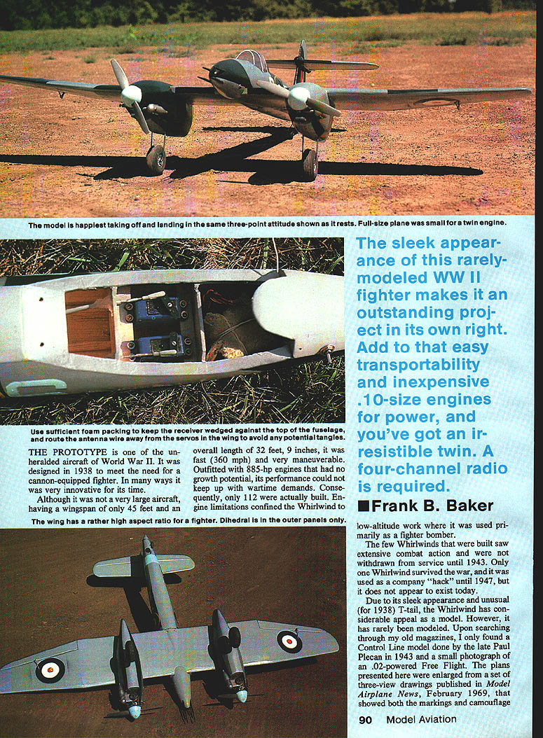
The sleek appearance of this rarely modeled World War II fighter makes it an outstanding project in its own right. Add easy transportability and inexpensive .10-size engines for power, and you've got an irresistible twin. A four-channel radio is required.
The Prototype
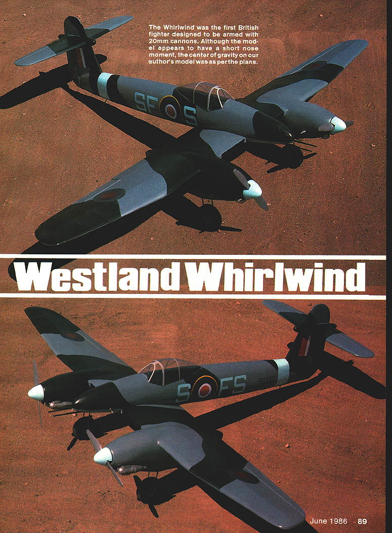
The Whirlwind was one of the unheralded aircraft of World War II. Designed in 1938 to meet the need for a cannon-equipped fighter, it was innovative for its time. Although not a large aircraft (wingspan 45 ft; overall length 32 ft 9 in), it was fast (about 360 mph) and very maneuverable. Outfitted with 885-hp engines that had little growth potential, its performance could not keep pace with wartime demands; consequently, only 112 were built. Engine limitations confined the Whirlwind to low-altitude work where it was used primarily as a fighter-bomber.
The few Whirlwinds built saw extensive combat action and were withdrawn from service by 1943. Only one survived the war and was used as a company "hack" until 1947; it does not appear to exist today.
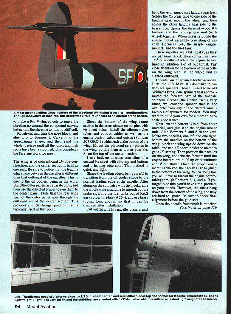
Due to its sleek appearance and its unusual (for 1938) T-tail, the Whirlwind has considerable appeal as a model, yet it has been rarely modeled. References found include a control-line model by the late Paul Plecan (1943), a small photograph of an .02-powered free-flight, and a set of three-view drawings published in Model Airplane News, February 1969, showing markings and camouflage.
Good documentation is hard to find. The best reference located by the author was a two-page description and photograph in Planemakers No. 2: Westland, available from Jane's Publishing Co. ($15.95). Write to Jane's Publishing Co., 4th Floor, 115 5th Ave., New York, NY 10003.
For model use, the author designed the model for two O.S. Max .10 FSR engines, resulting in a 54 in. wingspan. The relatively large size compared to small engines requires very light construction. The wing is made detachable so the model will fit into smaller car trunks.
Construction
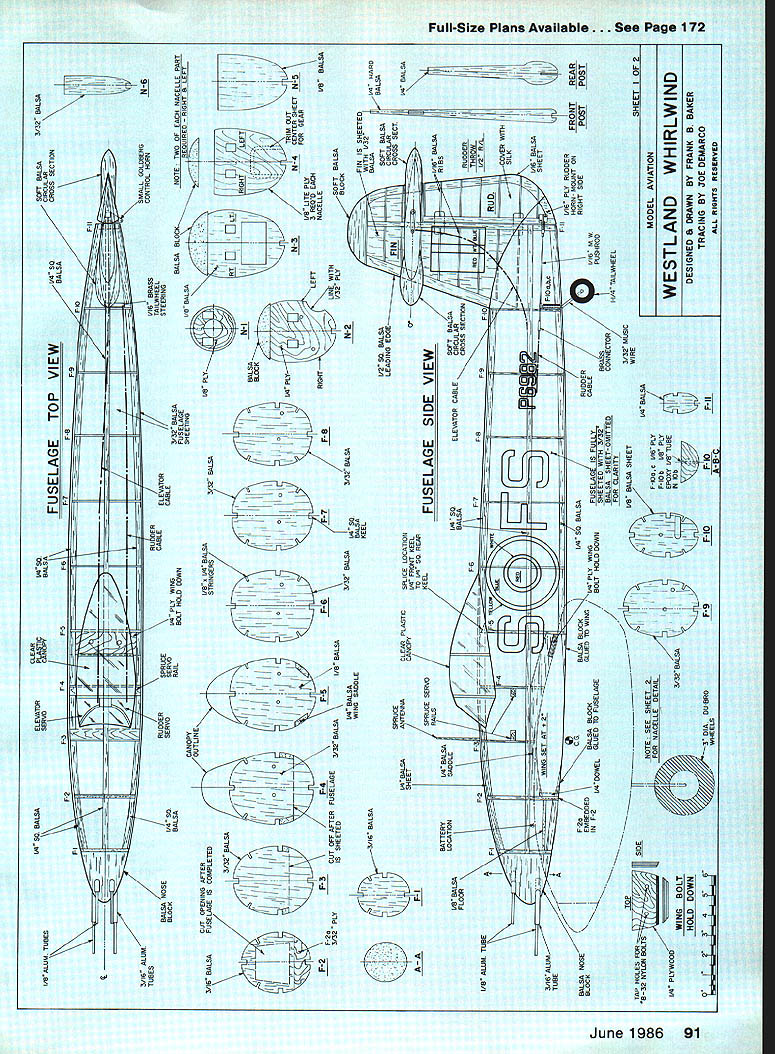
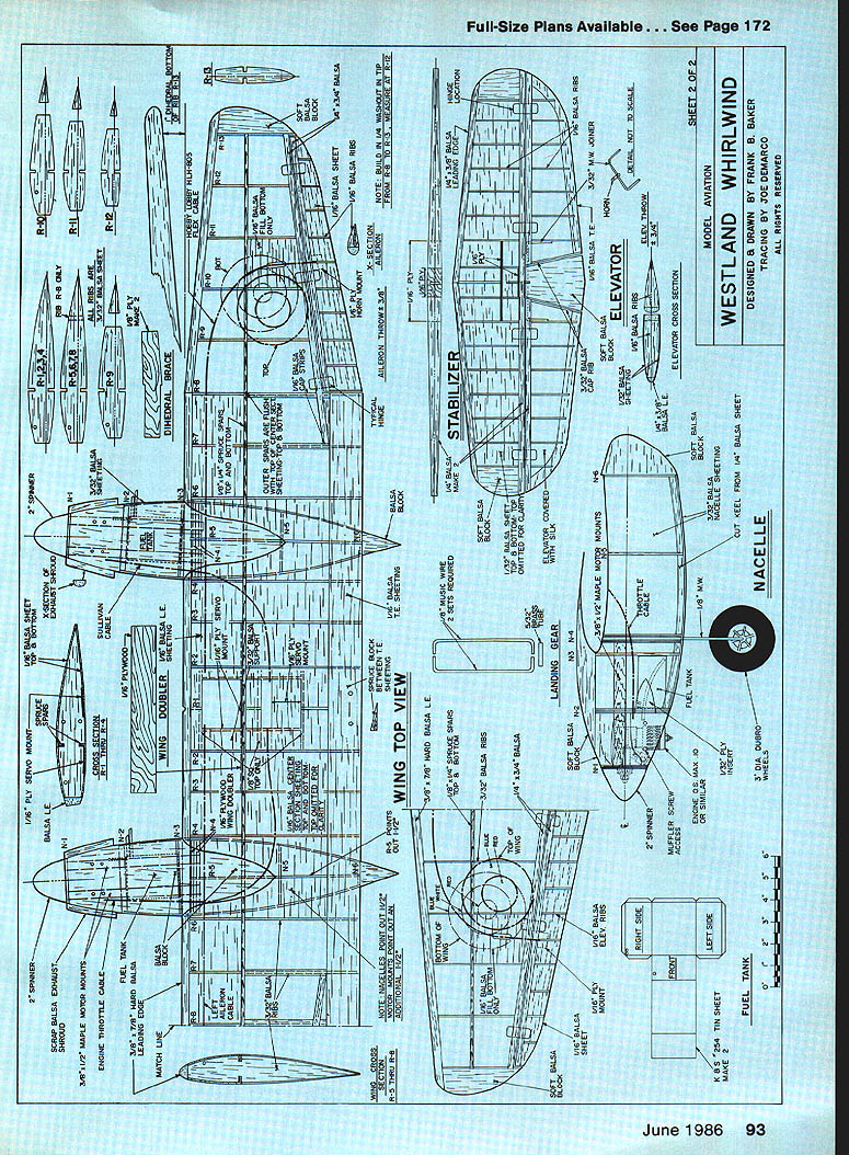
Due to the T-tail configuration, the construction sequence departs from the usual wing-first approach; begin with the fuselage framework and follow with the tail assembly. Major materials mentioned are balsa (various densities and thicknesses), 1/32-in. and 1/16-in. sheets, Lite Ply, maple engine mounts, brass and music wire, and K&S solder tinplate for fuel tanks.
- Fuselage framework
- Build the basic fuselage framework using formers with 1/4-in. square and 1/8 x 1/4-in. stringers.
- Note: Former 2 includes a 1/16-in. plywood section embedded into it.
- Curved stringer sections from Former 4 forward are cut from 1/8-in. sheet and spliced to the 1/4-in. square stock before installation.
- Glue in place the 1/4-in. sheet wing saddle between Formers 2 and 5.
- Install the steerable tailwheel mechanism.
- Side sheeting
- Glue on side sheeting using 3/32-in. medium balsa. Soak the sheet in hot water with a bit of ammonia to aid bending.
- Position the bottom edge about 3/8 in. above the wing trailing edge and parallel to the side stringer.
- Use liberal amounts of white glue (the author prefers Pica Glu because it sands well), pins, and masking tape to hold sheeting in place.
- Check fuselage straightness after sheeting is attached.
- Tail assembly
- Build the tail assembly using very lightweight balsa for surfaces; use hard balsa for the fin post.
- Construct the elevator like a T-tail sailplane with the horn buried within the vertical fin.
- Install hinges and connect the elevator. Glue the stabilizer to the vertical fin, checking vertical and horizontal alignment.
- Note: the brass horn goes through the fin post. Install the rudder and its hinges.
- Control runs and final tail installation
- Run rudder and elevator nylon tubing and control cables through the fuselage and elevator tubing up the fin. The author used Hobby Lobby bulk-pack nylon tube with braided cable (HLHB 805).
- Insert a 3/32-in. music-wire "Z" into the end of the elevator horn and solder it to the elevator cable. Run a short wire to the rudder cable and a "Z" piece to the tailwheel arm.
- Cut out Former 11 to fit the fin post, slip the T-tail assembly onto the fuselage, pin it in place, and ensure the fin is vertical and the elevator spar is perpendicular to the centerline.
- Check that both rudder and elevator can be moved from the servo area.
- Sheet the vertical fin and stabilizer with 1/32-in. balsa, then glue the whole assembly to the fuselage. Trim fuselage side sheeting where it meets the vertical fin as shown on the plans.
- Cover the top and bottom of the fuselage with soft 3/32-in. balsa (the author used four sheets to cover completely).
- Nose and final fuselage shaping
- Rough-cut and trim the nose block, glue it onto Former 1, carve to approximate shape, and sand the whole fuselage until joints and high spots are smooth.
Wing and ailerons
- The wing is of conventional D-tube construction. The center section is built as one unit; outer panels are built separately and joined with dihedral braces.
- Note: the leading edge shape between the nacelles differs from that outboard of the nacelles because of the oil coolers in the wing.
- The rear wing spar of the outer panel passes through the outboard rib of the center section for a stronger junction.
- Sheet the bottom of the wing center section in areas shown on the plan with 1/16-in. balsa.
- Install aileron nylon tubes and control cables, plus engine control tubes and cables (Sullivan 507 GRC-3) which exit at the bottom of the wing.
- Mount plywood servo plates in the wing as low as possible. Sheet the top of the center section.
- Ailerons: built-up construction using a central 1/8-in. sheet with ribs top and bottom and a leading-edge spar for a quick, light assembly.
- Shape leading edges carefully, fairing oil cooler shapes to the normal nacelle leading edge. Glue on soft balsa wing tip blocks and sand smooth.
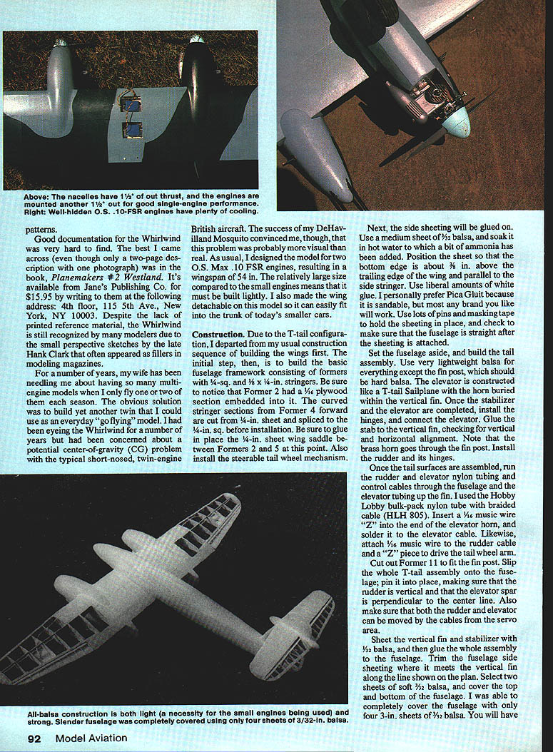
Nacelles, engines, and landing gear
- Build fuel tanks from K&S easy-solder tinplate (#254) and use brass tubing long enough to trim after installation.
- Cut Lite Ply nacelle formers and bend 1/8-in. music wire landing gear legs.
- Solder a 3/32-in. brass tube to one side of the landing gear, mount the wheel, then solder the other side to the brass tube.
- Epoxy the three plywood #4 formers and the landing gear unit (with wheel) together.
- Build the engine mount assembly: nacelle Formers 1–4, maple engine mounts, and fuel tank.
- Nacelles are banana-shaped: centerlines have 1.5° of out-thrust and the engine beams add another 1.5° of out-thrust. Pay close attention to the top view on the plan since each nacelle is slanted outboard.
- The author used old Williams Bros. 2-in. spinners approximating the forward part of to-scale spinners because O.S. Max .10s do not like large spinners, and true British blunt spinners are not available commercially. You may choose to make custom spinners for a more scale appearance.
Installing nacelles on the wing
- Cut the bottom 1/4-in. keel from sheet material and glue it to the engine mount unit. Glue Formers 5 and 6 to the keel.
- Make two nacelles (left and right).
- Mount nacelles to the bottom of the wing: block the wing upside down and use a Robart incidence meter to get a -2° setting. Position nacelles and trim formers until engine bearers are at 0° up/downthrust and 3° outthrust.
- Thread engine control tubing through Formers 2, 3, and 4 before final gluing—failure to do so creates difficult problems later.
- Once aligned and glued, attach sheeting, top block, and rear blocks. The top block should be near final shape before attachment.
- Install engines and spinners, glue in blocks at engine sides, carve and sand nacelles.
- Cut triangular areas in nacelle sheeting and glue in 3/32-in. plywood half-rounded gussets under the muffler; maintain about 3/32-in. clearance between muffler and plywood.
- Engines mounted with the specified outthrust plus another 1/4° outthrust can give improved single-engine performance. Well-hidden O.S. .10-FSR engines provide ample cooling in flight.
Final wing-fuselage assembly
- Cut away fuselage sheeting below the wing saddle and trim until the fuselage seats properly on the wing.
- Use a 2° incidence meter to set the wing at +2° incidence while the stabilizer is at 0°. Ensure wings and stabilizer are parallel and perpendicular to the centerline.
- Glue in the 1/4-in. plywood wing screw-down plate, the front and back bottom wing blocks, and the 1/4-in. birch dowel on Former 2.
- Use a round file to notch the center of the wing leading edge to match the dowel. Remount wings and align spars perpendicular to the fuselage centerline.
- Drill pilot holes for wing hold-down screws, tap wing mount plate holes, and drill wing holes for tie-down bolts.
- Mount servo rails inside the fuselage.
- Cut cannons from 3/16- and 3/32-in. aluminum tubing and epoxy together. Mark cannon holes on the nose block and drill them—this is delicate work; use filler to hide errors but avoid gluing the cannons into the nose block.
- Carve a balsa block to the canopy outline shown on the plans. The author formed a canopy from Sig 1/2-in. butyrate sheet; a commercial canopy can be trimmed to fit.
Finishing
- The author recommends Red Devil "One Time" spackling compound as a very lightweight filler. It can be a bit stiff to apply (wetting the sheeting slightly helps); it sands well and produces a smooth surface.
- Apply filler to blocks and sheeted areas, sand smooth, then brush on a coat of primer and sand again.
- The author's covering method: silk covering, followed by multiple brush coats of clear dope and Aerokote to fill pores. One sprayed coat of aluminum was used as an opaque undercoat.
- Paint scheme: one coat of Cessna gray overall; bottom sprayed Cessna gray lightened with white. Green areas were Stinson green darkened with red and black.
- Roundels and lettering were masked with contact shelf paper and spray-painted (the author prefers painting insignia rather than using decals due to inconsistent decal dimensions).
- When paint is dry, install the canopy and cannons.
Flying
- The model takes off and lands best in the same three-point attitude shown in the plans. On takeoff it rolls a relatively short distance, breaks ground in a three-point attitude, and climbs in that attitude.
- In level flight it picks up speed and performs quick rolls and leisurely loops well.
- On early landings the author experienced nosing over onto the back; the Whirlwind prefers to land in a three-point, tail-low attitude (similar to flying a J-3 Cub). Once this was learned, landing reliably became easy.
- Overall, the Whirlwind is an unusual and enjoyable model with distinctive appearance in the air and on the ground. It is easy to fly and small enough to fit in a car and your pocketbook.
Notes and references
- Plans here were enlarged from a three-view in Model Airplane News, February 1969.
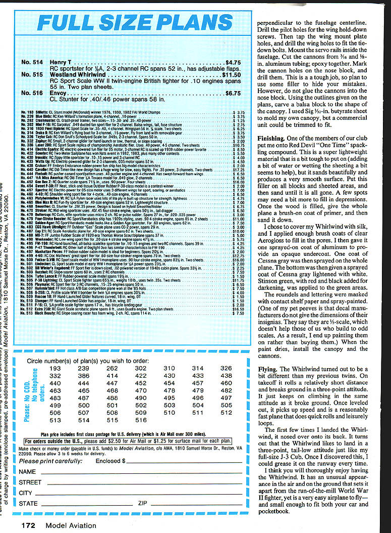
- Best reference found: Planemakers No. 2: Westland (Jane's Publishing Co.), available for $15.95. Address: Jane's Publishing Co., 4th Floor, 115 5th Ave., New York, NY 10003.
Transcribed from original scans by AI. Minor OCR errors may remain.

