
What's in the Box?
An inside look at the components in radio transmitters and receivers
L.F. Randolph
This piece is not intended to make anyone become an electronic technician; it offers some insight into the things that go inside the boxes we call transmitters and receivers.
Failure of our equipment is rarely caused by a failure of one of the basic parts. More often than not, the cause is cell failure in a battery pack or a broken connection in the exterior wiring. Those are the weakest links in our systems—not all those little pieces on the inside! Let's take a closer look at what's in the box.
The electronic parts that are inside the things that fly our airplanes are the same ones that bring us our favorite television show, make the ignition work in our cars, wake us in the morning to music, and even talk to us on our computers. In fact, they are everywhere!
Since radio was discovered more than a century ago—and it was more or less an accidental discovery at that—it's reasonable to assume that the methods of generating radio signals must not be too complicated, or else they would not have been discovered in the first place! It also follows that the component parts were rather simple devices, and although they have changed in size, they do the same jobs now that they did then.
Those of us who have grown up with radio and television take them for granted, and we seldom glance behind the dial or screen.
We take the same approach to our radio control systems. Properly plugged together they work, and if not, off they go to the factory for repair. That practice is a good one, in the case of the television set, because there are some very high voltages in them that can cause us great damage. But there is nothing in our battery-operated radios that could cause any harm.
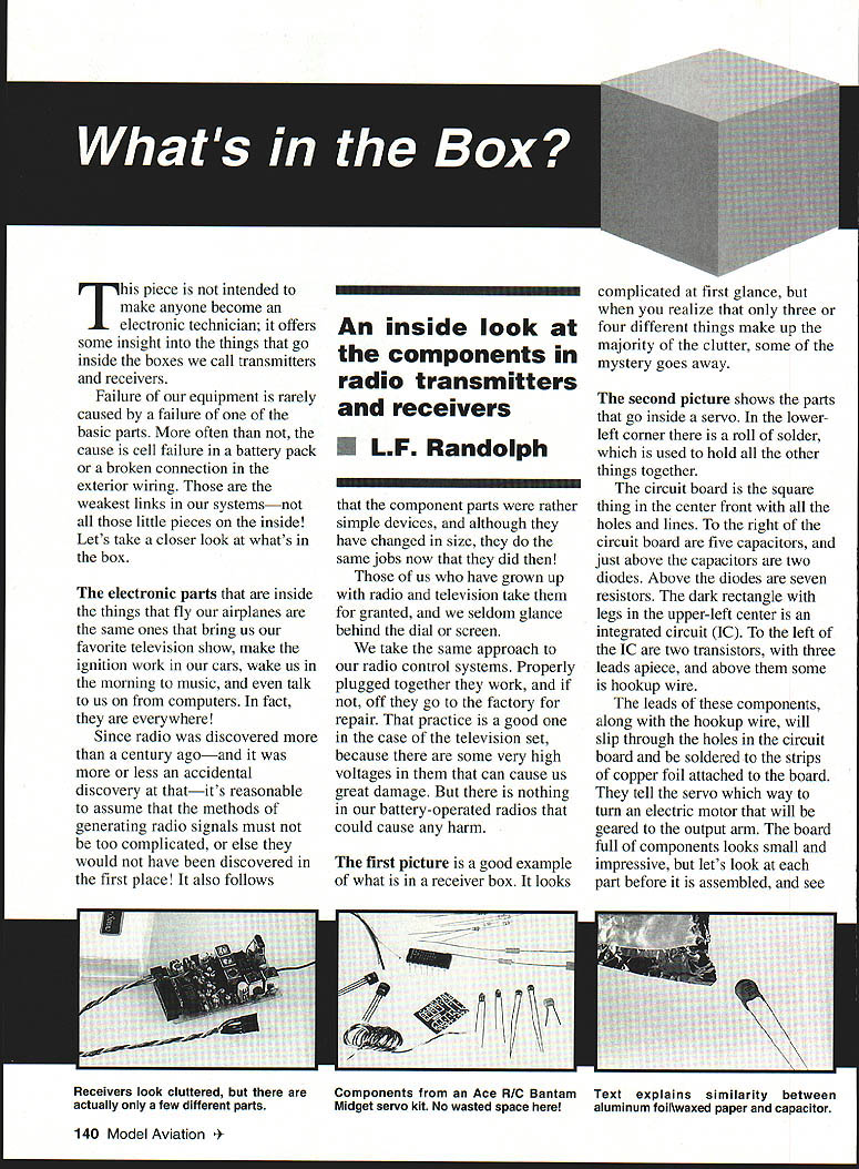
The first picture is a good example of what is in a receiver box. It looks complicated at first glance, but when you realize that only three or four different things make up the majority of the clutter, some of the mystery goes away.
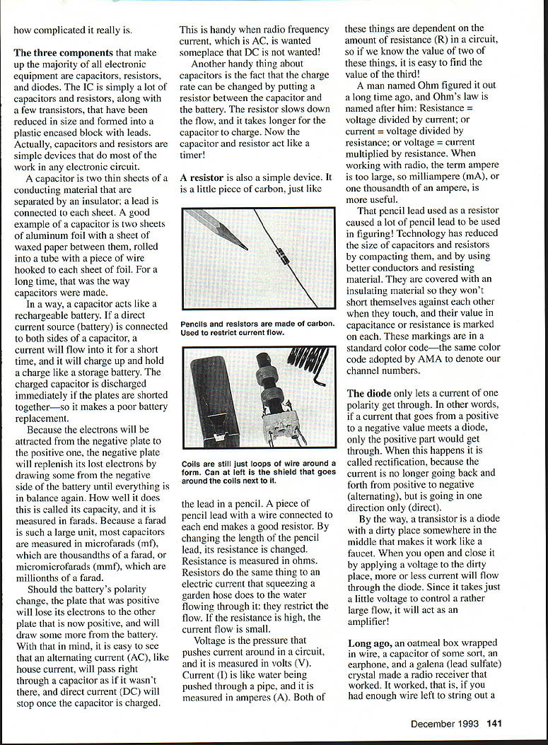
The second picture shows the parts that go inside a servo. In the lower-left corner there is a roll of solder, which is used to hold all the other things together.
The circuit board is the square thing in the center front with all the holes and lines. To the right of the circuit board are five capacitors, and just above the capacitors are two diodes. Above the diodes are seven resistors. The dark rectangle with legs in the upper-left center is an integrated circuit (IC). To the left of the IC are two transistors, with three leads apiece, and above them some hookup wire.
The leads of these components, along with the hookup wire, will slip through the holes in the circuit board and be soldered to the strips of copper foil attached to the board. They tell the servo which way to turn an electric motor that will be geared to the output arm. The board full of components looks small and impressive, but let's look at each part before it is assembled, and see how complicated it really is.
The three components that make up the majority of all electronic equipment are capacitors, resistors, and diodes. The IC is simply a lot of capacitors and resistors, along with a few transistors, that have been reduced in size and formed into a plastic-encased block with leads. Actually, capacitors and resistors are simple devices that do most of the work in any electronic circuit.
A capacitor is two thin sheets of a conducting material that are separated by an insulator; a lead is connected to each sheet. A good example of a capacitor is two sheets of aluminum foil with a sheet of waxed paper between them, rolled into a tube with a piece of wire hooked to each sheet of foil. For a long time, that was the way capacitors were made.
In a way, a capacitor acts like a rechargeable battery. If a direct current source (battery) is connected to both sides of a capacitor, a current will flow into it for a short time, and it will charge up and hold a charge like a storage battery. The charged capacitor is discharged immediately if the plates are shorted together—so it makes a poor battery replacement.
Because the electrons will be attracted from the negative plate to the positive one, the negative plate will replenish its lost electrons by drawing some from the negative side of the battery until everything is in balance again. How well it does this is called its capacity, and it is measured in farads. Because a farad is such a large unit, most capacitors are measured in microfarads (mf), which are thousandths of a farad, or micromicrofarads (mmf), which are millionths of a farad.
Should the battery's polarity change, the plate that was positive will lose its electrons to the other plate that is now positive, and will draw some more from the battery. With that in mind, it is easy to see that an alternating current (AC), like house current, will pass right through a capacitor as if it wasn't there, and direct current (DC) will stop once the capacitor is charged.
This is handy when radio frequency current, which is AC, is wanted someplace that DC is not wanted!
Another handy thing about capacitors is the fact that the charge rate can be changed by putting a resistor between the capacitor and the battery. The resistor slows down the flow, and it takes longer for the capacitor to charge. Now the capacitor and resistor act like a timer!
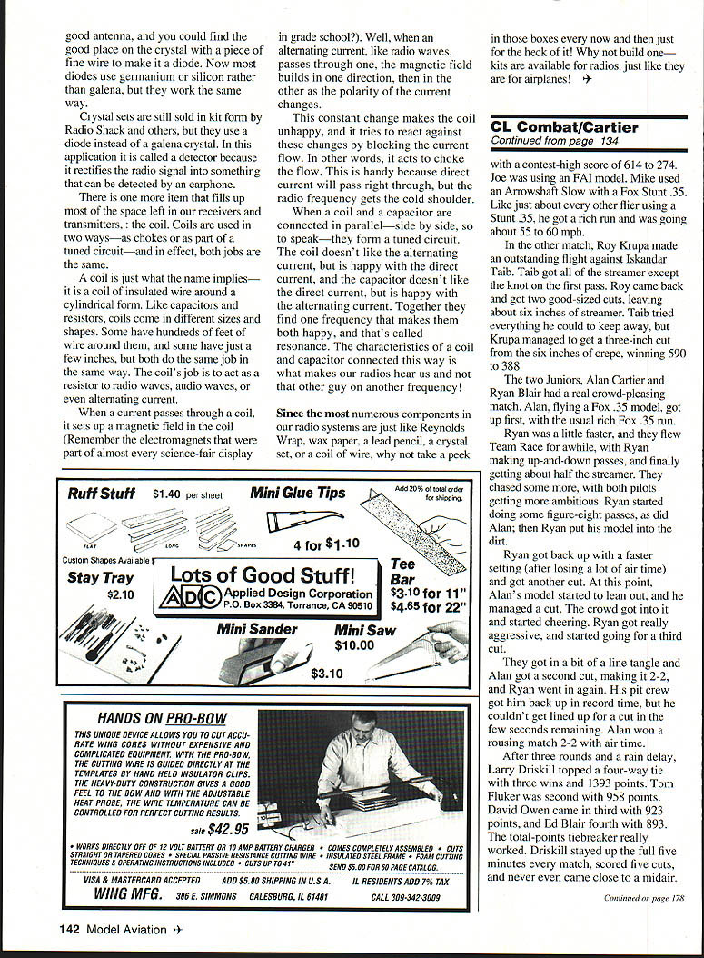
A resistor is also a simple device. It is a little piece of carbon, just like the lead in a pencil. A piece of pencil lead with a wire connected to each end makes a good resistor. By changing the length of the pencil lead, its resistance is changed. Resistance is measured in ohms. Resistors do the same thing to an electric current that squeezing a garden hose does to the water flowing through it: they restrict the flow. If the resistance is high, the current flow is small.
Voltage is the pressure that pushes current around in a circuit, and it is measured in volts (V). Current (I) is like water being pushed through a pipe, and it is measured in amperes (A). Both of these things are dependent on the amount of resistance (R) in a circuit, so if we know the value of two of these things, it is easy to find the value of the third!
A man named Ohm figured it out a long time ago, and Ohm's law is named after him:
- Resistance = voltage divided by current (R = V / I)
- Current = voltage divided by resistance (I = V / R)
- Voltage = current multiplied by resistance (V = I × R)
When working with radio, the term ampere is too large, so milliampere (mA), or one thousandth of an ampere, is more useful.
That pencil lead used as a resistor caused a lot of pencil lead to be used in figuring! Technology has reduced the size of capacitors and resistors by compacting them, and by using better conductors and resisting material. They are covered with an insulating material so they won't short themselves against each other when they touch, and their value in capacitance or resistance is marked on each. These markings are in a standard color code—the same color code adopted by AMA to denote our channel numbers.
The diode only lets a current of one polarity get through. In other words, if a current that goes from a positive to a negative plate meets a diode, only the positive part would get through. When this happens it is called rectification, because the current is no longer going back and forth from positive to negative (alternating), but is going in one direction only (direct).
By the way, a transistor is a diode with a dirty place somewhere in the middle that makes it work like a faucet. When you open and close it by applying a voltage to the dirty place, more or less current will flow through the diode. Since it takes just a little voltage to control a rather large flow, it will act as an amplifier!
Long ago, an oatmeal box wrapped in wire, a capacitor of some sort, an earphone, and a galena (lead sulfate) crystal made a radio receiver that worked. It worked, that is, if you had enough wire left to string out a good antenna, and you could find the good place on the crystal with a piece of fine wire to make it a diode. Now most diodes use germanium or silicon rather than galena, but they work the same way.
Crystal sets are still sold in kit form by Radio Shack and others, but they use a diode instead of a galena crystal. In this application it is called a detector because it rectifies the radio signal into something that can be detected by an earphone.
There is one more item that fills up most of the space left in our receivers and transmitters, the coils. Coils are used in two ways—as chokes or as part of a tuned circuit—and in effect, both jobs are the same.
A coil is just what the name implies—it is a coil of insulated wire around a cylindrical form. Like capacitors and resistors, coils come in different sizes and shapes. Some have hundreds of feet of wire around them, and some have just a few inches, but both do the same job in the same way. The coil's job is to act as a resistor to radio waves, audio waves, or even alternating current.
When a current passes through a coil, it sets up a magnetic field in the coil (remember the electromagnets that were part of almost every science-fair display in grade school?). Well, when an alternating current, like radio waves, passes through one, the magnetic field builds in one direction, then in the other as the polarity of the current changes.
This constant change makes the coil unhappy, and it tries to react against these changes by blocking the current flow. In other words, it acts to choke the flow. This is handy because the current will pass right through, but the radio frequency gets the cold shoulder.
When a coil and a capacitor are connected in parallel—side by side, so to speak—they form a tuned circuit. The coil doesn't like the alternating current, but is happy with the direct current, and the capacitor doesn't like the direct current, but is happy with the alternating current. Together they find one frequency that makes them both happy, and that's called resonance. The characteristics of a coil and capacitor connected this way is what makes our radios hear us and not that other guy on another frequency!
Since the most numerous components in our radio systems are just like Reynolds Wrap, wax paper, a lead pencil, a crystal set, or a coil of wire, why not take a peek in those boxes every now and then just for the heck of it! Why not build one—kits are available for radios, just like they are for airplanes!
Transcribed from original scans by AI. Minor OCR errors may remain.

