
The White Electrician
When I saw the RC Combat model built by Svetlana Filippova of Russia, I was so motivated that I began developing the White Electrician. I have never actively participated in control-line flying, but I have always been intrigued by the extended wing-to-tail configurations flown in control-line combat. Svetlana's RC Combat version immediately suggested the resemblance to a typical control-line combat model and inspired me to explore its potential in electric aerobatics.
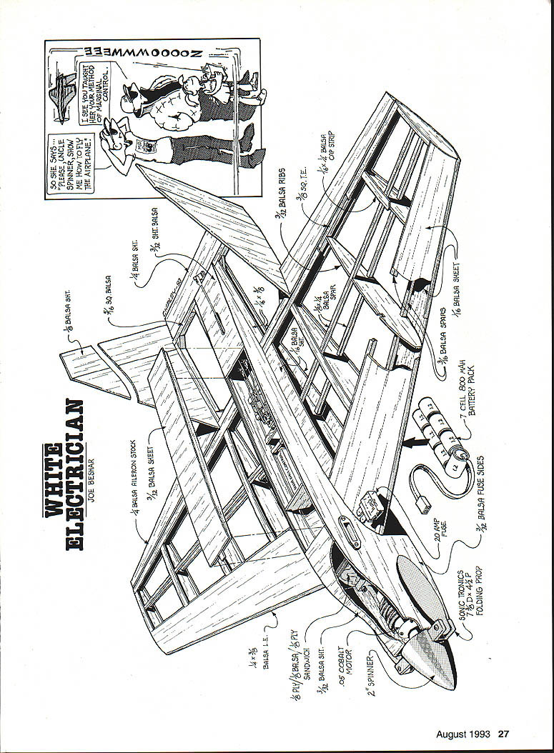
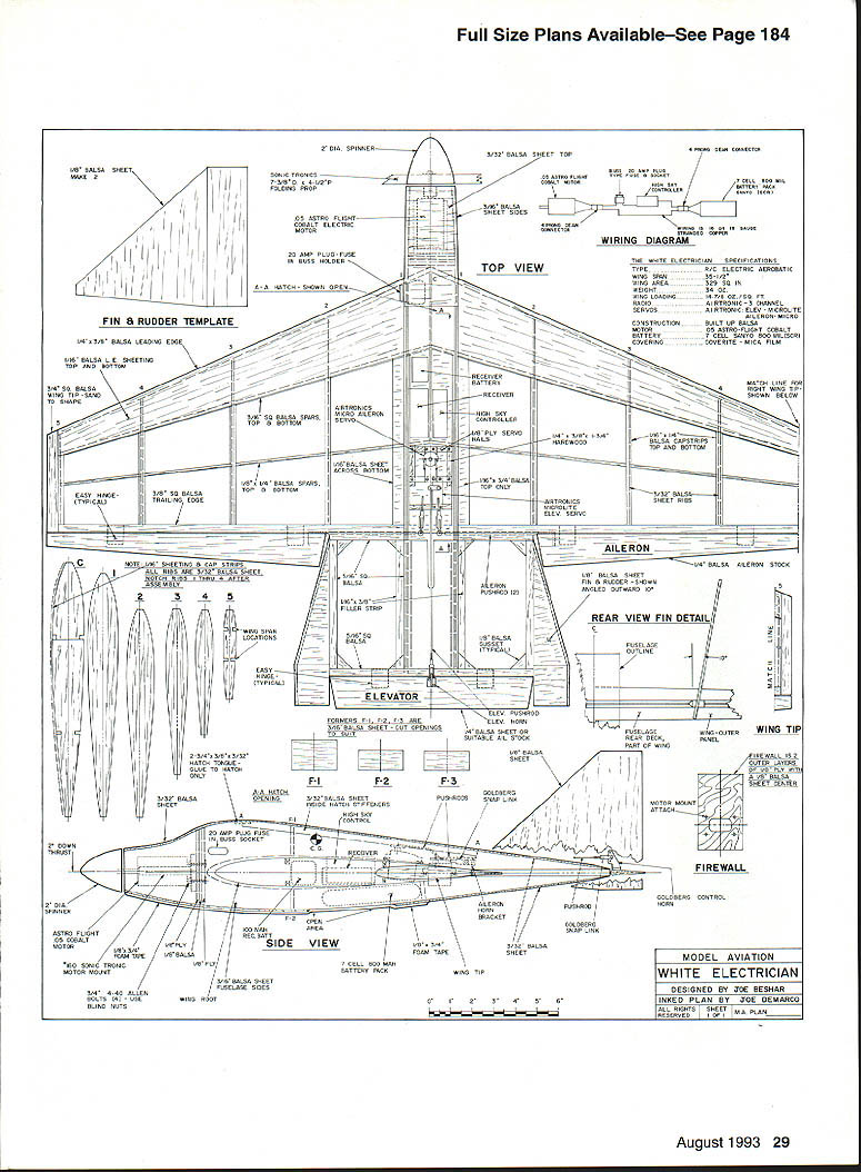
I bashed Svetlana's design, making construction and design changes to convert it to an electric-powered acrobatic model. The White Electrician is basically all-balsa construction, employing an Astro Flight .05 cobalt motor powered by seven Sanyo 800‑mAh Ni‑Cd cells. Although there has been controversy about electric aircraft performance, building this model should eliminate any doubt — it has very high performance and is capable of any maneuver.
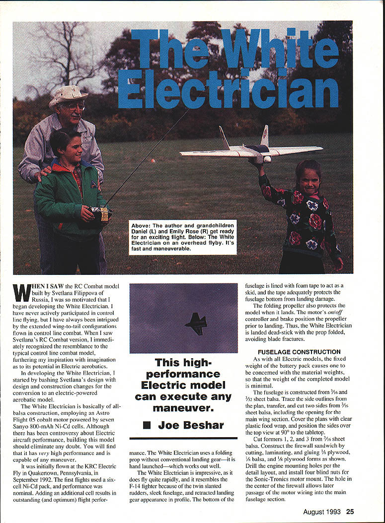
The model was initially flown at the KRC Electric Fly in Quakertown, Pennsylvania, in September 1992. The first flights used a six-cell Ni‑Cd pack and performance was nominal; adding an additional cell resulted in outstanding (and optimum) flight performance. The White Electrician uses a folding prop with conventional landing gear and is hand launched. The bottom of the fuselage is lined with foam tape to act as a skid and protect the fuselage from landing damage.
The folding propeller also protects the model on landing: the motor's on/off controller and brake position the propeller prior to landing so the White Electrician is landed dead-stick with the prop folded, avoiding blade fractures. This high-performance electric model can execute any maneuver.
Joe Beshar
Fuselage Construction
As with all electric models, the fixed weight of the battery pack makes it important to minimize material weights so the completed model is as light as possible.
Construction materials and layout:
- Sides: trace outlines from the plan and cut two sides from 3/16" sheet balsa, including the opening for the main wing section.
- Formers: cut formers 1, 2, and 3 from 3/16" sheet balsa.
- Firewall: construct a laminated sandwich (3/32" plywood / 1/8" balsa / 3/32" plywood) as shown on the plans. Drill engine-mounting holes per the layout and install four blind nuts. The center hole in the firewall allows later passage of motor wiring into the main fuselage section.
- Cross-sheeting: top and bottom fuselage cross-sheeting is 3/32" balsa, providing the open hatch location shown on the plans. The open portion on the fuselage bottom leaves the battery pack accessible; a removable sheeting battery access hatch is used.
- Stiffeners and hatch: install 3/32" sheet inside stiffener rails, profiled and glued as shown. Cut, assemble, and glue two holders for the front hatch so the hatch can slide and retain the battery while still allowing easy removal.
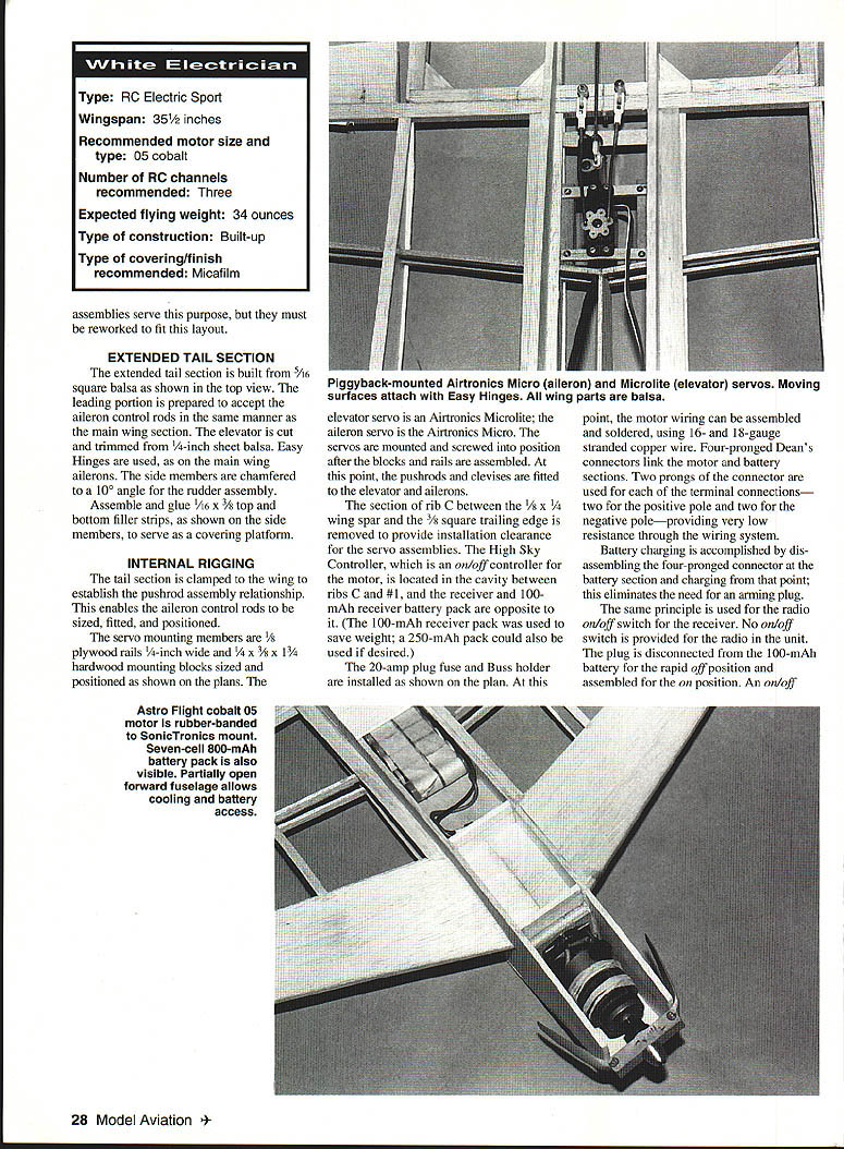
- Motor mount: attach the Sonic-Tronics electric motor mount to the firewall with 3/8"‑long 4‑40 Allen‑head cap screws. The Astro Flight .05 cobalt motor is attached to the mount and held in position with rubber bands (the author prefers #62 rubber bands wound tightly around the motor). Using rubber bands gives flexibility in the motor mounting and helps avoid damage in a crash. Plastic wrappers supplied with some mounts are an alternative.
- Battery retention and cooling: the bottom fuselage next to the battery compartment is left open to provide cooling and to allow removal of the battery for changeover. A small piece of Velcro between the battery pack and the compartment can hold the battery if the fit is not tight.
Assemble and glue the sandwiched firewall and formers over the top view shown on the plans and complete cross‑sheeting and hatch details as indicated.
Wing Construction
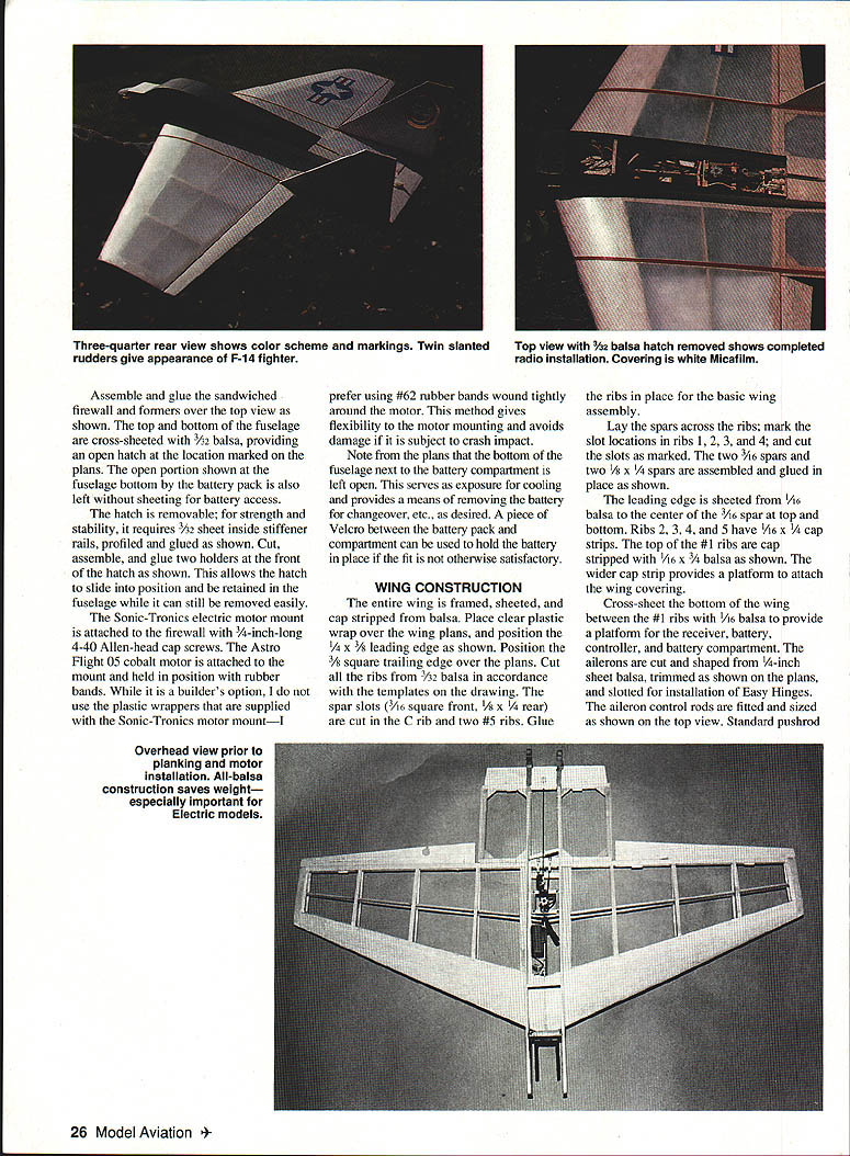
The entire wing is framed, sheeted, and cap-stripped from balsa.
Materials and steps:
- Cover the wing plans with clear plastic wrap.
- Leading edge: position the 1/4" x 3/8" leading edge as shown.
- Trailing edge: position the 3/32" square trailing edge over the plans.
- Ribs: cut all ribs from 3/32" balsa per the templates. Cut spar slots (3/16" square front, 1/8" x 1/4" rear) in rib C and two #5 ribs where indicated.
- Spars: lay the spars across the ribs, mark and cut slot locations in ribs 1–4. Install two 3/16" spars and two 1/8" x 1/4" spars, assembled and glued in place as shown.
- Leading-edge sheeting: sheet the leading edge with 1/16" balsa to the center of the 3/16" spar at top and bottom.
- Cap strips: ribs 2–5 receive 1/16" x 1/4" cap strips; top of the #1 ribs are cap‑stripped with 1/16" x 3/32" balsa to provide a platform for the wing covering.
- Bottom cross-sheeting: cross-sheet the bottom of the wing between the #1 ribs with 1/16" balsa to provide a platform for the receiver, battery, controller, and battery compartment.
- Ailerons: cut and shape ailerons from 1/4" sheet balsa, trim as shown on the plans, and slot for Easy Hinges. Fit and size aileron control rods per the top view. Use standard pushrod installation.
Extended Tail Section
- Build the extended tail section from 5/16" square balsa as shown in the top view.
- Prepare the leading portion to accept the aileron control rods in the same manner as the main wing section.
- Elevator: cut and trim the elevator from 1/4" sheet balsa and hinge with Easy Hinges.
- Rudder assembly: chamfer the side members to a 10° angle for the rudder assembly.
- Filler strips: glue 1/16" x 3/8" top and bottom filler strips to the side members to serve as a platform for covering.
Internal Rigging
- Tail alignment: clamp the tail section to the wing to establish pushrod relationships; this enables the aileron control rods to be sized, fitted, and positioned.
- Servo mounts: use 1/8" plywood rails, 1/4" wide, and 1/8" x 3/8" x 1-1/2" hardwood mounting blocks sized and positioned per the plans.
- Servos: elevator servo — Airtronics Micro; aileron servo — Airtronics MicroLite. Mount and screw servos into position after blocks and rails are assembled. Fit pushrods and clevises to elevator and ailerons.
- Clearance: remove the section of rib C between the 1/8" x 1/4" wing spar and the 3/8" square trailing edge to provide installation clearance for the servo assemblies.
- Electronics layout:
- High Sky on/off controller for the motor is located in the cavity between ribs C and #1.
- Receiver and a 100‑mAh receiver battery pack are installed opposite the controller (a 250‑mAh pack may be used if preferred).
- Install a 20‑amp plug fuse and Buss holder as shown on the plan.
- Wiring: assemble and solder motor wiring using 16‑ and 18‑gauge stranded copper wire. Use four‑pronged Dean's connectors between motor and battery sections, with two prongs for each of the positive and negative poles to provide very low resistance.
- Charging and switches: battery charging is accomplished by disconnecting the four‑pronged connector at the battery section and charging from that point, eliminating the need for an additional arming plug. The radio on/off is accomplished by disconnecting the receiver battery plug; an on/off switch can be employed if desired, but this adds weight and may compromise the design's weight goals.
Assembly
- Covering: the fuselage is covered with Coverite Micafilm; apply Balsarite where adhesion is desired. Micafilm is light, strong, heat‑shrinkable, and heat‑adhering.
- Wing and tail: after covering the fuselage, permanently assemble the wing and position the tail section, capturing the aileron control rods and gluing the tail in place. Cover the wings and extended tail after assembly.
- Control surfaces: ailerons and elevator are covered, disassembled, and installed with Easy Hinges, then glued permanently in place with cyanoacrylate (CyA).
- Rudders: cover the rudders entirely except for the area where adhesion to the extended tail is required; trim the Micafilm at the glue joint for a strong bond.
- Finishing: apply foam tape skid strips to the bottom of the fuselage. Add decals and any cosmetic trim to complete the White Electrician.
Flying
- Preflight checks:
- Check all controls for correct direction and movement.
- Verify the center of gravity is at the location shown on the side view.
- Charge the batteries and confirm receiver capacity.
- With the seven‑cell Sanyo 800‑mAh pack installed, plug the 100‑mA receiver pack in, ensure the throttle on the transmitter is in the off position, and install the fuse in the Buss plug just prior to launch.
- Launch: hand‑launch the model briskly into the wind. Be aware of the high‑performance characteristics of this model — even the slightest control movement can significantly adjust the attitude of the White Electrician.
Good luck and good flying!
Transcribed from original scans by AI. Minor OCR errors may remain.

