

Wild Hare
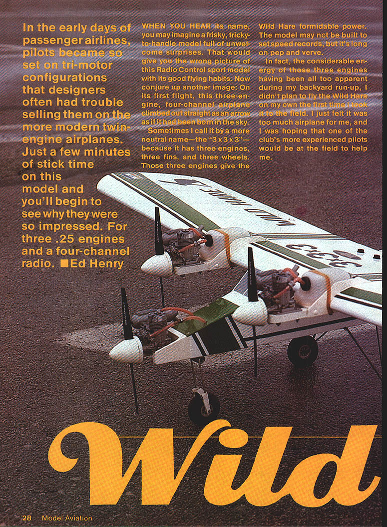
In the early days of passenger airlines, pilots became so set on tri‑motor configurations that designers often had trouble selling them on the more modern twin‑engine airplanes. Just a few minutes of stick time on this model and you'll begin to see why they were so impressed. It is powered by three .25 engines and uses a four‑channel radio.
When you hear its name, you may imagine a frisky, tricky‑to‑handle model full of unwelcome surprises. That would give you the wrong picture of this radio‑control sport model with its good flying habits. On its first flight, this three‑engine, four‑channel airplane climbed out straight as an arrow as if it had been born in the sky.
Sometimes I call it by a more neutral name—the "3 x 3 x 3"—because it has three engines, three fins, and three wheels. Those three engines give the Wild Hare formidable power. The model may not be built to set speed records, but it's long on pep and verve.
In fact, the considerable energy of those three engines, having been all too apparent during my backyard run‑up, I didn't plan to fly the Wild Hare on my own the first time I took it to the field. I just felt it was too much airplane for me, and I was hoping that one of the club's more experienced pilots would be at the field to help me.
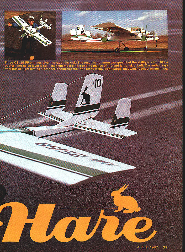
Three OS .25 FP engines give this rabbit its kick. The result is not more top speed but the ability to climb like a tractor. The noise level is still less than most single‑engine planes of .40 and larger size. After lots of flight testing my model is solid as a rock and ready to go. The model flies with no offset on anything.
Although the day was beautiful, with mild sunshine and no wind, only one thing was missing. After waiting two hours, my friend Louie turned up at the field. Since no one else had shown up, I decided to make a high‑speed taxi run rather than call it a day. I didn't think Louie could handle the Wild Hare by himself, so I felt it better to wait until the three engines were running and synchronized, hoping someone else would come along.
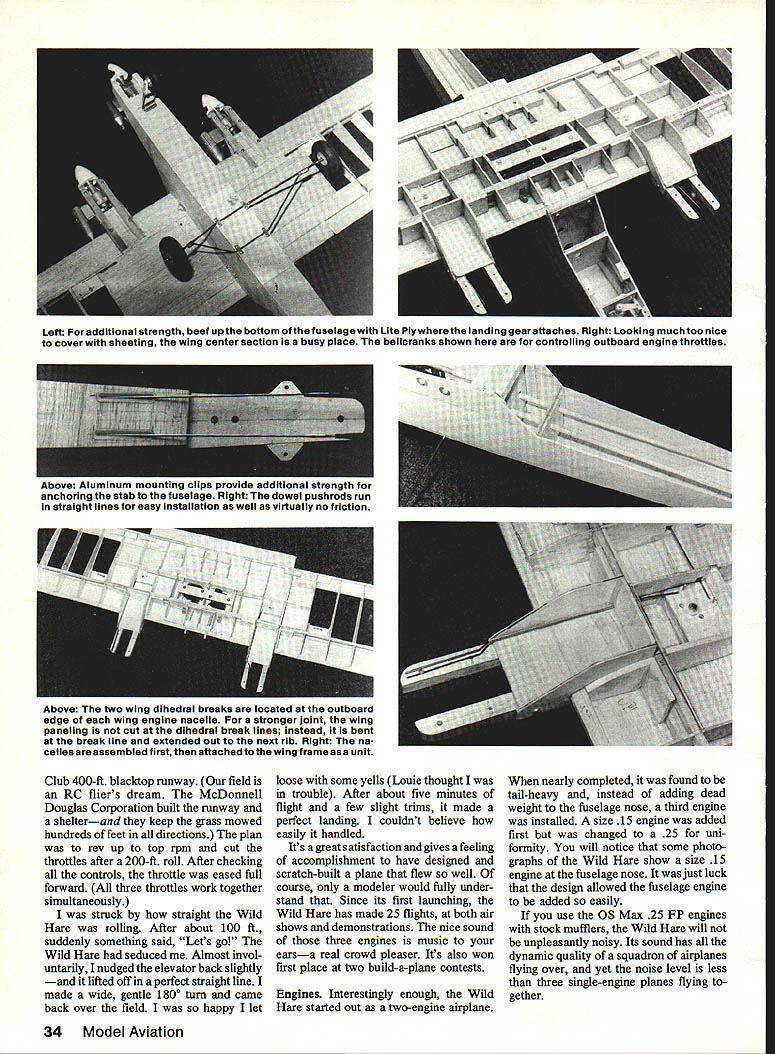
I carefully placed the Wild Hare, range‑checked the radio and prepared for the run. Plenty of sheeting on the center section adds much strength to the wing. The fuel tank for the center engine is accessible through a hatch in the fuselage.
Club 400‑ft. blacktop runway. Our field is an RC flier's dream—the McDonnell Douglas Corporation built the runway and a shelter, and they keep the grass mowed hundreds of feet in all directions. The plan was to rev up to top rpm and cut the throttles after a 200‑ft. roll. After checking all the controls, the throttle was eased full forward. (All three throttles work together simultaneously.)
I was struck by how straight the Wild Hare was rolling. After about 100 ft., suddenly something said, "Let's go!" The Wild Hare had seduced me. Almost involuntarily, I nudged the elevator back slightly—and it lifted off in a perfect straight line. I made a wide, gentle 180° turn and came back over the field. I was so happy I let loose with some yells (Louie thought I was in trouble). After about five minutes of flight and a few slight trims, it made a perfect landing. I couldn't believe how easily it handled.
It's a great satisfaction and gives a feeling of accomplishment to have designed and scratch‑built a plane that flew so well. Since its first launching, the Wild Hare has made 25 flights, at both air shows and demonstrations. The nice sound of those three engines is music to your ears—a real crowd pleaser. It's won first place at two build‑a‑plane contests.
Engines
Interestingly enough, the Wild Hare started out as a two‑engine airplane.
When nearly completed, it was found to be tail‑heavy and, instead of adding dead weight to the fuselage nose, a third engine was installed. A size .15 engine was added first but was changed to a .25 for uniformity. You will notice that some photographs of the Wild Hare show a size .15 engine at the fuselage nose. It was just luck that the design allowed the fuselage engine to be added so easily.
If you use the OS Max .25 FP engines with stock mufflers, the Wild Hare will not be unpleasantly noisy. Its sound has all the dynamic quality of a squadron of planes flying over, and yet the noise level is less than three single‑engine planes flying together.
Construction
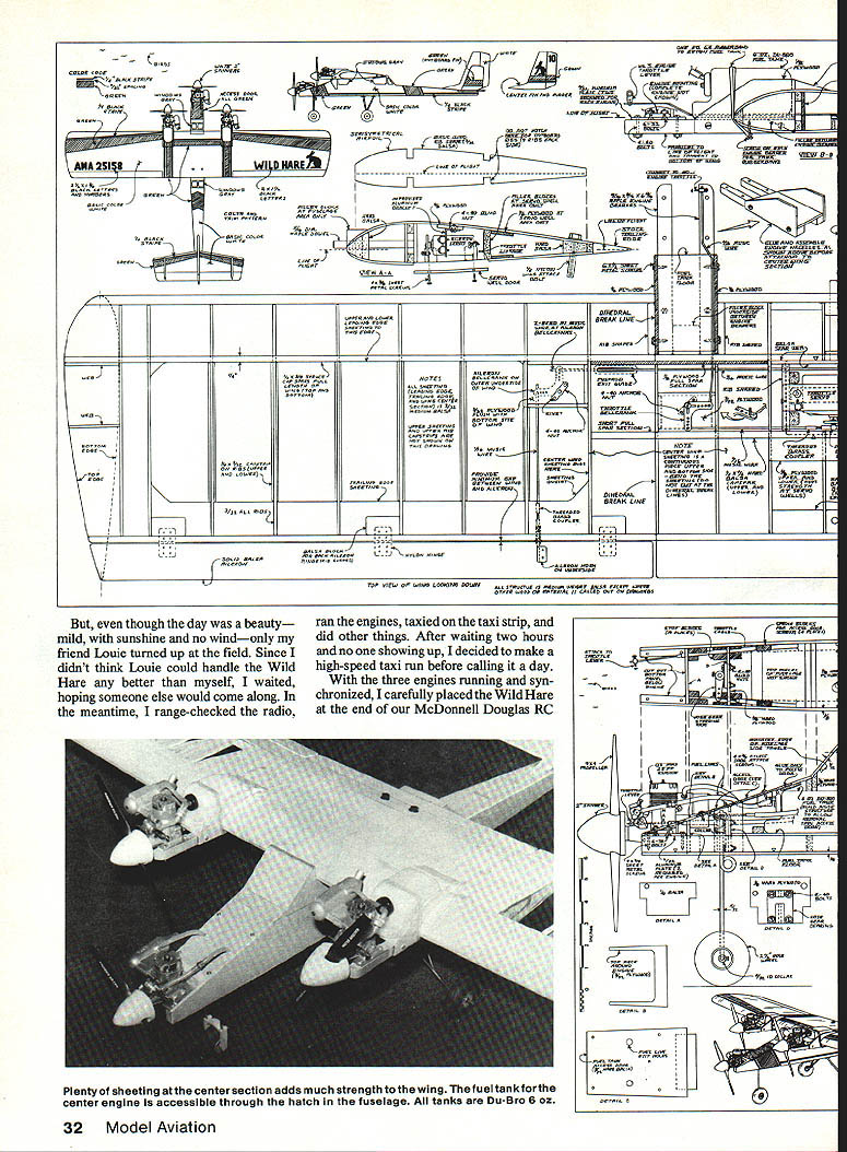
As always when building from full‑size plans, use the plans for dimensions and layout as much as possible, but be sure to match‑shape and match‑fit the final size of any part to the related parts. Also, holes should always be match‑drilled with related parts. Sometimes the paper on which the plans are printed shrinks, or even expands, creating small discrepancies in the dimensions. When all parts are match‑fitted and match‑drilled, however, these differences become unimportant.
The Wild Hare is set up with zero degree angle of incidence throughout. All surfaces and all engines—wing, horizontal stabilator, up/down and left/right of all three engines—are at zero degree of incidence. The airplane even sits on the ground at zero degree incidence. How, then, does the Wild Hare maintain lift? Very simple: the semi‑symmetrical wing has adequate lift at zero degree angle of attack. It must be right, because the Wild Hare flies beautifully.
Wing Construction
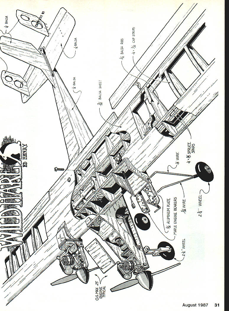
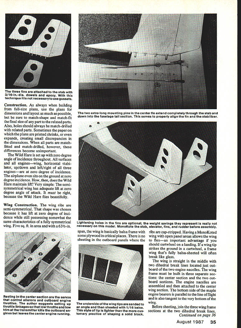
The wing ribs are semi‑symmetrical. That shape was chosen because it has lift at zero degree of incidence while still possessing somewhat the same characteristics of a fully symmetrical wing. Five sq. ft. in area and with a 63‑1/2‑in. span, the wing is basically a balsa frame with some plywood in critical places. There is no sheeting in the outboard panels where the ribs are cap‑stripped. Having a MonoKoted wing with open panel areas allows the wing to flex—an important advantage if you should cartwheel on a landing. If a wing tip strikes the ground in a cartwheel, a frame wing that's fully balsa‑sheeted will often break like glass.
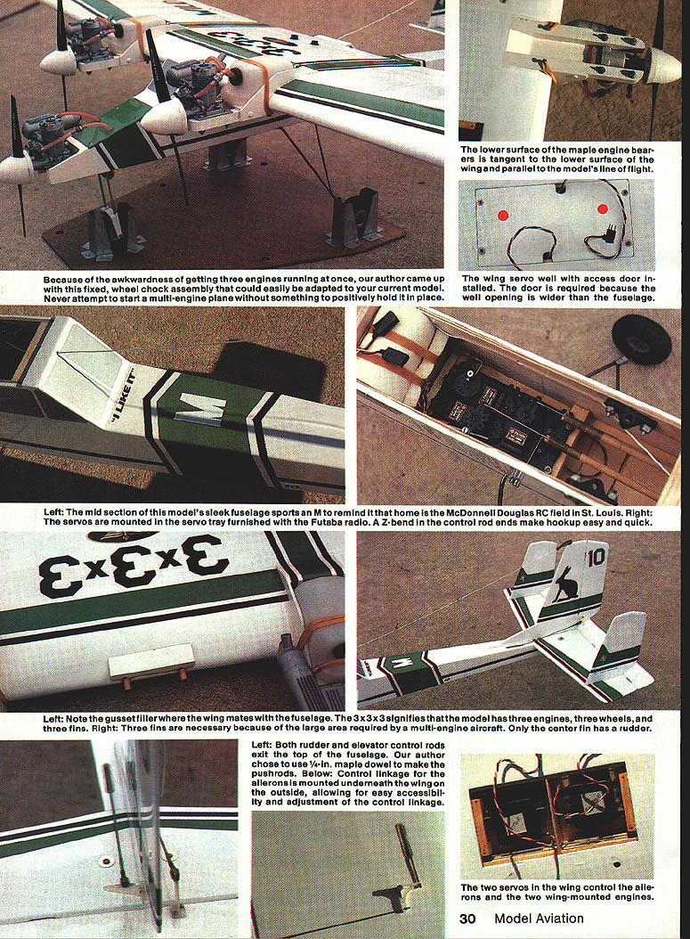
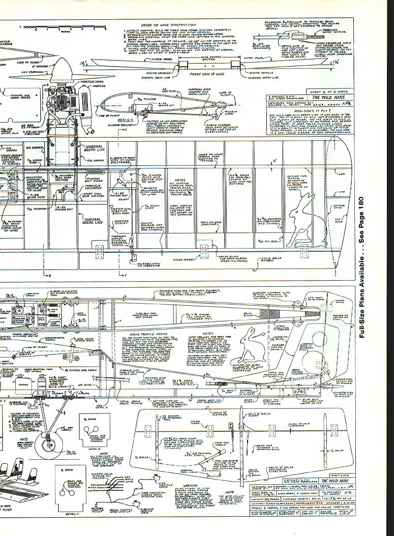
The wing is straight in the middle with two dihedral break lines located just outboard of the two engine nacelles. The wing frame must be built in three separate sections: the center section and the two outboard sections. The engine nacelles are assembled and then attached to the center wing section. The bottom side of the maple engine bearers is parallel to the line of flight and is also tangent to the very bottom of the wing.
Before sheeting, join the three wing frame sections at the two dihedral break lines. Then sheet only the bottom side of the wing. Do not cut the sheeting at the dihedral break lines. Instead, bend it and extend it out to the next rib—a technique which adds great strength to the wing.
Install the aileron servo and the throttle servo in the wing. (The single servo controls both wing engines.) Install all servo linkages and all other internal wing items.
After all internal wing work is completed, install the top wing sheeting. As with the bottom sheeting, do not cut it at the dihedral break lines. All wing ribs and paneling are 3/32‑in. medium‑weight balsa. The wing and all other areas of the airplane are MonoKoted.
Fuselage Construction
Fuselage construction is easy and straightforward. Two spruce longerons (3/8 x 5/16‑in.) run the full length of the 43‑in. fuselage. First, assemble the 1/8‑in. balsa side panels, spruce longerons, all bulkheads, and tail blocks. Install the bottom and top fuselage sheeting last. The bottom of the fuselage is parallel to the ground and to the line of flight.
Empennage
It is common knowledge that a multi‑engined airplane is easier to control if it has plenty of vertical fin area, and the Wild Hare has three vertical fins. All three fins and the horizontal stabilator are made of 1/4‑in. medium‑weight balsa. A rudder is used only on the center fin.
Each fin is attached to the stabilator with five or six 1/16‑in.‑diameter maple dowel pins. The pins are one inch long and are mounted into the base of the fins. When installed, they extend 1/8 in. from the base of the fins and are flush with the bottom side of the stabilator. Holes for the pins are cut into the stab with 5/32‑in.‑diameter thin‑walled brass tubing, with one end of the tubing sharpened from the inside. Pushing and rotating the sharpened tube cuts a clean hole in the balsa.
The ribs and the fins are installed with epoxy. Competently assembled, the empennage will be plenty strong, and gussets at the base of the fins won't be necessary.
Throttles
All throttles are operated simultaneously. Two servos control all three engine throttles. One servo is located in the wing for the two wing engines, with the other in the fuselage for the fuselage engine. The throttle setup is designed so that selecting low throttle and low throttle trim will shut off the wing engines, evening out the thrust and allowing operation on only the fuselage engine for minimum flight. With this feature, if one wing engine chokes off in flight, you can stop the remaining wing and continue on the center engine. Most of the time, I purposely land the airplane with only the center engine running. If you come in too high for landing, the center engine will even take the airplane around again.
The Wild Hare has never been flown with one wing engine stopped. My future plan is to put a limited amount of fuel in one wing tank so that that engine will cut off before the other one. It is possible that the airplane will remain controllable even with only one wing engine functioning. After all, there is plenty of fin area and the engines are closely coupled. However, if the Wild Hare does become erratic, I can always shut off the other outboard engine.
A special wiring harness must be used to operate the two throttle servos simultaneously. You can accomplish this by using a dual‑servo harness, available from most RC radio manufacturers. Or, you can save a few bucks by making your own harness from an extra aileron extension cable.
To make your own harness:
- Cut off the plug at one end of the aileron extension cable, leaving the cable and the socket.
- Splice this cable into the center of the throttle‑servo cable in the fuselage.
- Solder corresponding wire colors together and insulate the wires after soldering.
- Plug the wing throttle servo into the spliced cable socket.
The end product: two servos working for you instead of one.
Tips:
- The soldering of 1/16‑in. music wire to threaded brass couplers is a critical operation. Threaded brass couplers are often used at servo arms and control surface horns. If the soldering operation is not done properly, the solder between the steel music wire and the brass coupler will not hold. Never trust the solder contact alone to hold.
- Before applying the solder, use a file to make several small notches in the music wire where the soldering will occur. The notches will take the load. Also, use soldering paste and plenty of heat when soldering. Failure to use soldering paste can prevent the solder from bonding.
- This procedure also applies to the soldering of landing gear wires. The notches in the landing gear wire should be placed at the soldering area, which is then wrapped with .040‑in. diameter bare copper wire. Again, use soldering paste and ample heat. If you follow these procedures, ordinary solder can be used. Soldering paste is available at hardware stores and is the same type used by plumbers to solder copper water pipes.
All control linkages and control surfaces must operate freely with no binding. This is important because it prevents excessive drain on receiver batteries. The harder a servo has to work, the more drain it will place on the batteries. For example, an over‑tightened screw at a bellcrank bearing can cause the battery drain to be so high that your flights for the day could be cut in half. This could account for receiver battery failure occurring earlier than you had anticipated.
To check for linkage binding, mechanically disconnect the servo from the control linkage. The control surface hinges and all linkages should then work absolutely freely with no binding (not even a slight binding). This also includes the throttle and nose‑gear steering controls.
Engine Starting and Flight Characteristics
Engine Starting. Don't ever—and I repeat, don't ever—start a three‑engine airplane without first completely tying it down so that it cannot move forward or backward. Failure to tie the plane down could cause a high‑speed propeller to be driven into your hand or leg. One method I highly recommend is to build a simple wheel chock rig. Use the fixed wheel chock to immobilize the airplane when starting the engines. After all engines have been started and synchronized, lift the airplane up and out of the rig.
When starting, start both wing engines first and the center fuselage engine last. Which wing engine you start first depends on whether you are right‑handed or left‑handed. It's a good idea to have the needle valve preset on the center engine before starting. It's too late to reach for that needle valve with the wing engines operating—that's a "no‑no." Also, it's mandatory to use a tachometer to synchronize the engines' rpm, especially the two outboard wing engines. For the sake of safety, always use the tachometer and adjust the needle valves from behind the engines. The center engine really does not need to be synchronized.
How does it fly? Those three engines give the Wild Hare power like a tractor. Although it doesn't fly extremely fast, the airplane climbs out straight and flies where you point it. It'll climb out at a 45° angle to out of sight if you'll let it.
The first flight required hardly noticeable changes in trim settings. The Wild Hare does rolls, outside loops, inverted flight, and power‑on spins with ease. I could probably coax more out of it, but I'm not a hot‑dog pilot. Engine torque has some effect only on very tight maneuvers.
I plan to fly the Wild Hare with my Fly Seat—the full‑scale cockpit I designed for flying RC models. (The Fly Seat received magazine publicity ten or more years ago, and drew hundreds of letters from every civilized country in the world. Someday I'll donate it to the AMA Museum, but not until I fly the Wild Hare with it.) If you build one of these great‑flying, straight‑flying machines, write and tell me about it:
Ed Henry 25 Gold Run Dr. St. Peters, MO 63376 Tel. (314) 441‑5827
Transcribed from original scans by AI. Minor OCR errors may remain.

