

The Wildcat
By Hurst Bowers and Don Srull
Introduction
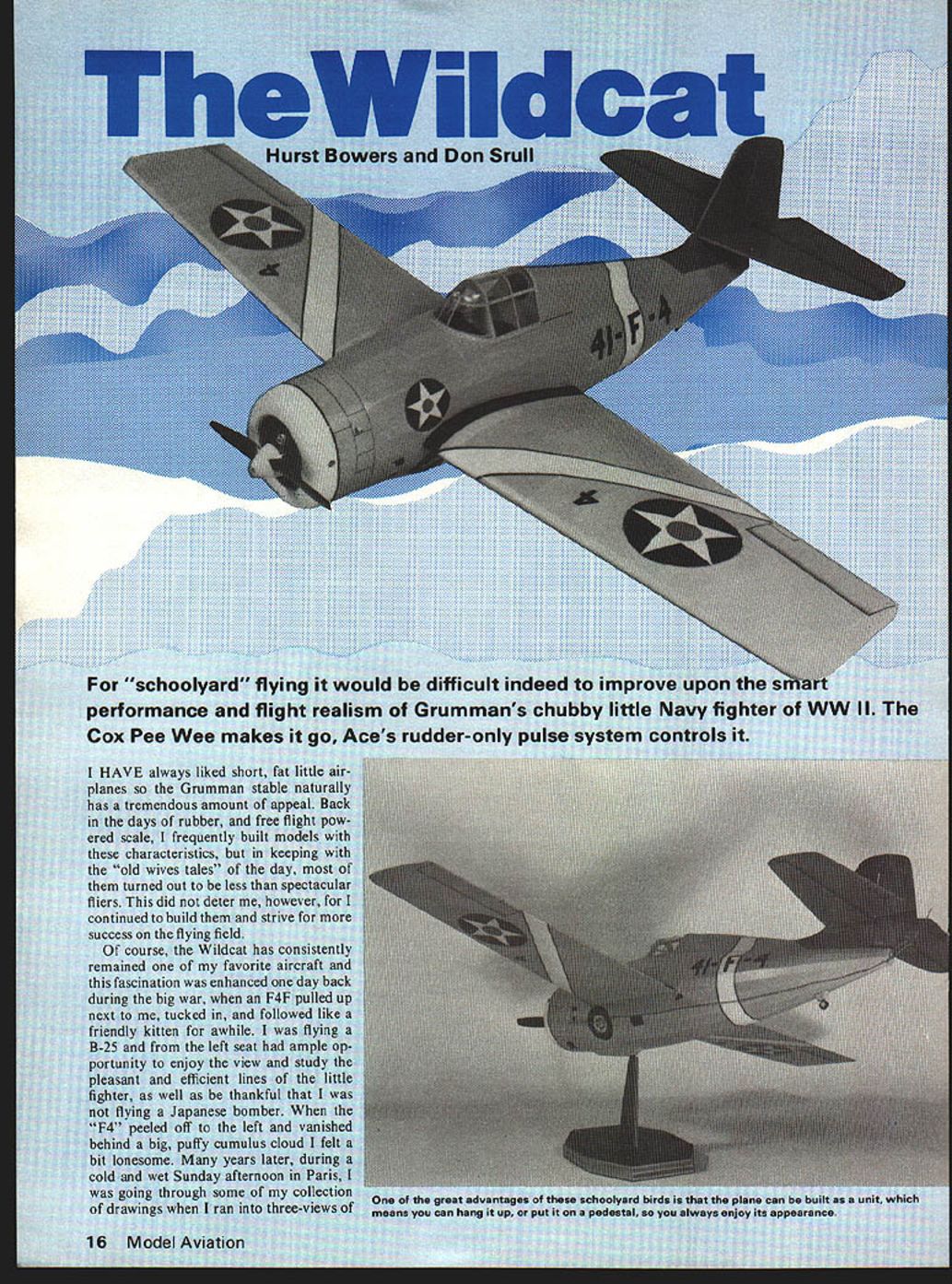
For "schoolyard" flying it would be difficult indeed to improve upon the smart performance and flight realism of Grumman's chubby little Navy fighter of WWII. The Cox Pee Wee makes it go; Ace's rudder‑only pulse system controls it.
I have always liked short, fat little airplanes, so the Grumman Wildcat naturally has a tremendous amount of appeal. Back in the days of rubber and free‑flight powered scale, I frequently built models with these characteristics, but in keeping with the "old wives' tales" of the day, most of them turned out to be less than spectacular fliers. This did not deter me, however, for I continued to build them and strive for more success on the flying field.
The Wildcat has consistently remained one of my favorite aircraft and this fascination was enhanced one day back during the big war, when an F4F pulled up next to me, tucked in, and followed like a friendly kitten for a while. I was flying a B‑25 and from the left seat had ample opportunity to enjoy the view and study the pleasant and efficient lines of the little fighter, as well as be thankful that I was not flying a Japanese bomber. When the F4F peeled off to the left and vanished behind a big, puffy cumulus cloud I felt a bit lonesome.
Many years later, during a cold and wet Sunday afternoon in Paris, I was going through some of my collection of drawings when I ran into three‑views of the Wildcat. I thought of my "wing man" of almost 20 years earlier and got out the drawing board to develop a model that I just knew would prove the "old wives" didn't know what they were talking about. I finished the plans and put them away to build later or when I had more time.
History
The story of the Grumman Wildcat is not new to most model‑aviation enthusiasts, and its combat record in the Pacific is legendary. When historians recount the events of Wake Island and Guadalcanal, the F4F comes to mind as one of the most outstanding participants. These were not the only engagements; there were many others as well, such as Rabaul and the Coral Sea, to name but a few.
According to Profile Publications Limited, 376 F4F variants were built, with 229 being deployed by the U.S. Navy and Marine Corps, primarily aboard the aircraft carriers of the day. Some were consigned to both the Greeks and the French, but delivery was diverted with their capitulation; Britain was the only Ally to use the aircraft, designated by then as the "Martlet."
The design first appeared in 1936 and the Bureau of Aeronautics contracted with Grumman for the first machine. In the competition that followed, it lost out to the Brewster Company's XF2A‑1, another "FLUF" (fat little ugly fellow); however, the world situation at the time precluded discarding such a promising aircraft.
Briefly, the vital statistics are:
- Wingspan: 35 ft.
- Length: 28 ft. 9 in.
- Gross weight: 7,065 lb
- Engine: R‑1830‑76, ‑86, ‑90 (about 1,200 hp)
- Maximum speed: 331 mph at 21,000 ft
- Service ceiling: 37,000 ft
- Range: 860 miles
Materials / Parts
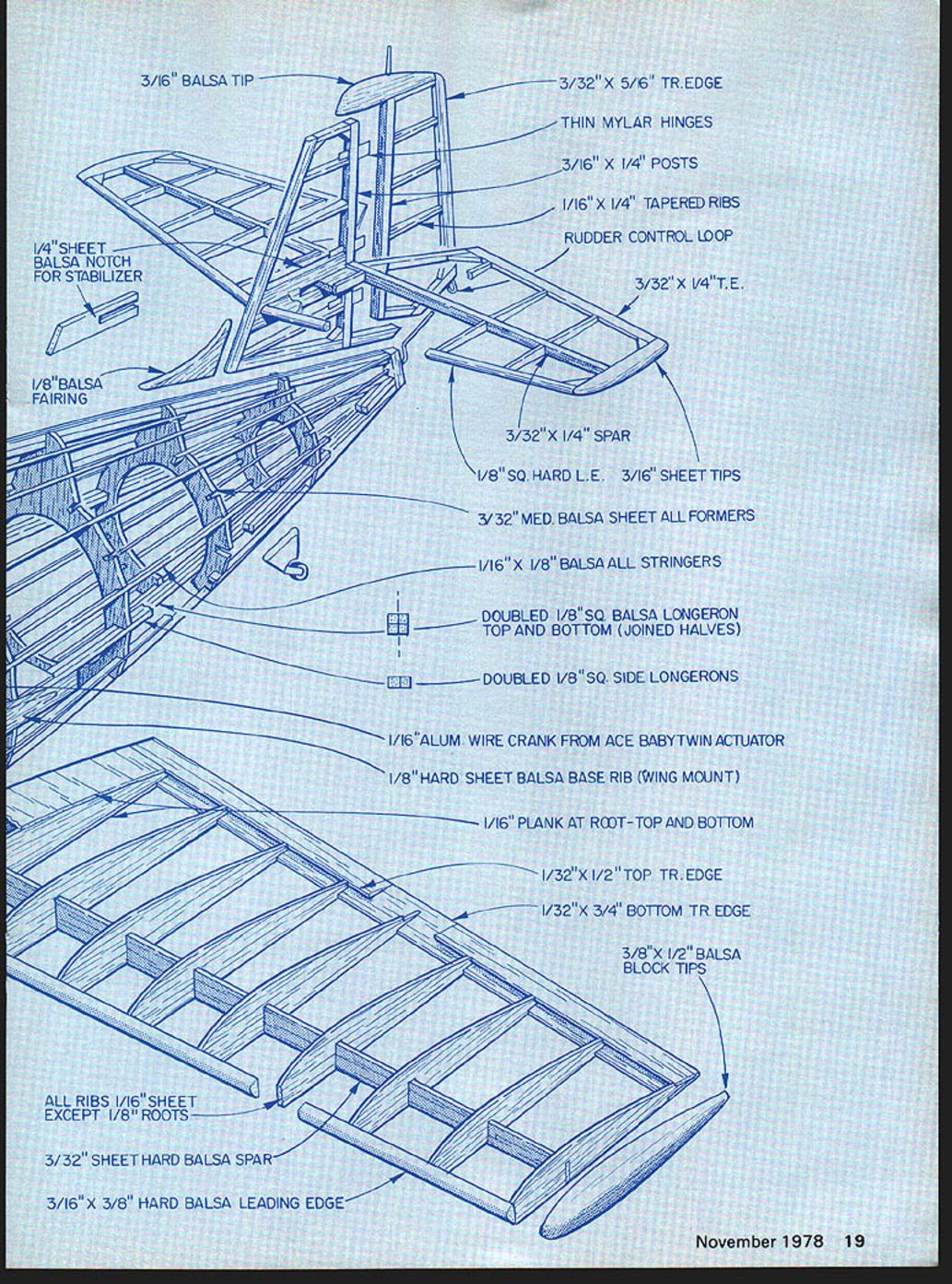
- 3/16" balsa tips
- 3/32" x 5/16" trailing edge (T.E.)
- Thin Mylar hinges
- 3/16" x 1/4" posts
- 1/16" x 1/4" tapered ribs
- Rudder control loop
- 3/32" x 1/4" trailing edge
- 3/32" x 1/4" spar
- 1/8" square hard leading edge (L.E.)
- 3/16" sheet tips
- 3/32" medium balsa sheet — all formers
- 1/16" x 1/8" balsa — all stringers
- Doubled 1/8" square balsa longeron — top and bottom (joined halves)
- Doubled 1/8" square side longerons
- 1/16" aluminum wire crank from Ace Baby Twin actuator
- 1/8" hard sheet balsa base rib (wing mount)
- 1/16" plank at root — top and bottom
- 1/32" x 1/2" top trailing edge
- 1/32" x 3/4" bottom trailing edge
- 3/8" x 1/2" balsa block tips
- All ribs 1/16" sheet except 1/8" roots
- 3/32" hard balsa sheet spar
- 3/16" x 3/8" hard balsa leading edge
- 1/4" sheet balsa notch for stabilizer
- 1/8" balsa fairing
Schoolyard Scale Concept
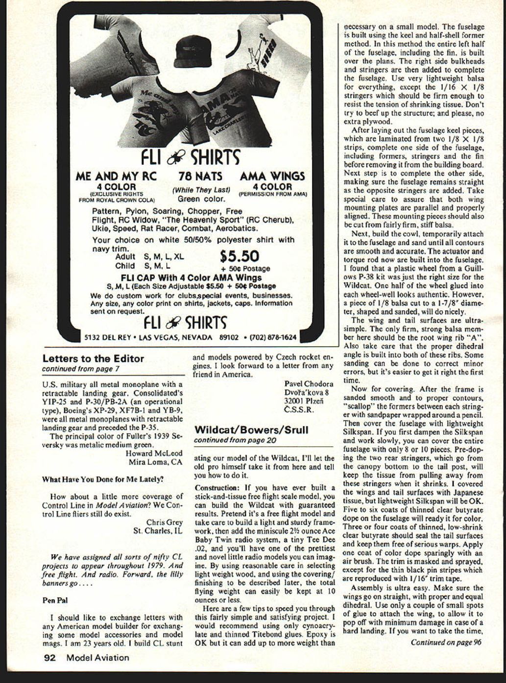
My basement workshop is frequently visited by such model‑aviation notables as Don Srull, one of the most outstanding modelers I know, as evidenced by his 1976, '77, and '78 winnings in the scale events at the Nationals. One night a couple of years ago, when "schoolyard scale" was in its formative stage, Don and I were looking at some of my old "must build later" drawings when we came to the Wildcat. It hit both of us as a natural for "schoolyard" flying with an .020 engine and pulse‑rudder radio control installed.
We agreed that it was light and simple enough to be safe and compatible with small flying sites.
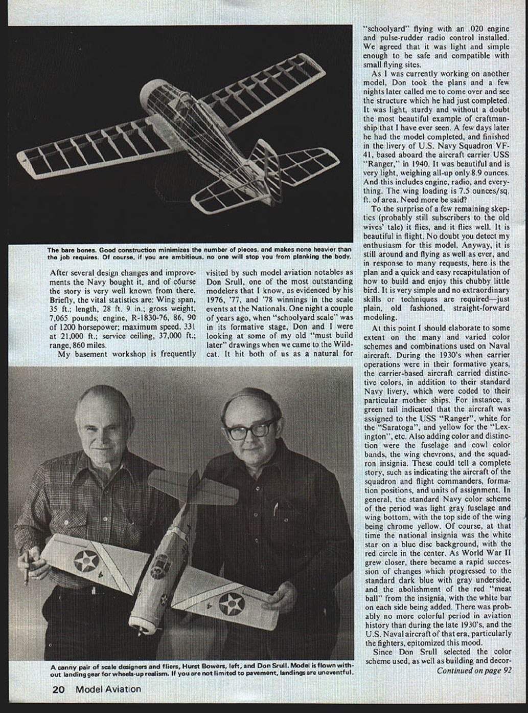
As I was currently working on another model, Don took the plans and a few nights later called me to come over and see the structure which he had just completed. It was light, sturdy and without a doubt the most beautiful example of craftsmanship that I have ever seen. A few days later he had the model completed, finished in the livery of U.S. Navy Squadron VF‑41, based aboard the aircraft carrier USS Ranger in 1940. It was beautiful and is very light, weighing all‑up only 8.9 ounces. This includes engine, radio, and everything. The wing loading is 7.5 ounces per sq. ft. of area.
To the surprise of a few remaining skeptics (probably still subscribers to the old wives' tale) it flies, and it flies well. It is beautiful in flight. In response to many requests, here is the plan and a quick and easy recapitulation of how to build and enjoy this chubby little bird. It is very simple and no extraordinary skills or techniques are required—just plain, old‑fashioned, straightforward modeling.
Colors and Markings
During the 1930s, when carrier operations were in their formative years, carrier‑based aircraft carried distinctive colors, in addition to standard Navy livery, coded to their particular mother ships. For instance:
- Green tail: USS Ranger
- White tail: USS Saratoga
- Yellow tail: USS Lexington
Also used were fuselage and cowl color bands, wing chevrons, and squadron insignia. These could indicate squadron and flight commanders, formation positions, and unit assignment.
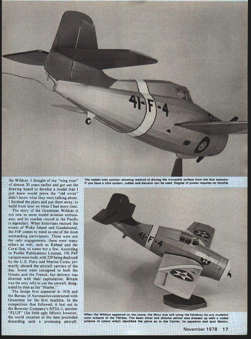
In general, the standard Navy color scheme of the period was a light gray fuselage and wing bottom, with the top side of the wing being chrome yellow. The national insignia at that time was the white star on a blue disc with a red circle in the center. As World War II approached, schemes changed rapidly to the standard dark blue with gray undersides, and the red "meat ball" was abolished, with white bars added on each side.
Don Srull selected the color scheme used on our model and handled the building and decorating. The following construction notes are largely his.
Construction
If you have ever built a stick‑and‑tissue free‑flight scale model, you can build the Wildcat with guaranteed results. Pretend it's a free‑flight model and take care to build a light and sturdy framework, then add the minuscule 2‑1/4 ounce Ace Baby Twin radio system, a tiny Tee Dee .020 engine, and you'll have one of the prettiest and most novel little radio models you can imagine.
By using reasonable care in selecting light‑weight wood and using the covering/finishing described below, the total flying weight can easily be kept at 10 ounces or less.
Here are a few tips to speed you through this fairly simple and satisfying project:
- Use only cyanoacrylate (CA) and thinned Titebond glues. Epoxy is OK but can add unnecessary weight on a small model.
- The fuselage is built using the keel and half‑shell former method: build the entire left half of the fuselage, including the fin, over the plans. Then add the right‑side bulkheads and stringers to complete the fuselage.
- Use very lightweight balsa for everything except the 1/16" x 1/8" stringers, which should be firm enough to resist the tension of shrinking tissue.
- Do not beef up the structure unnecessarily; avoid extra plywood.
Building the fuselage:
- Lay out the fuselage keel pieces, laminated from two 1/8" x 1/8" strips.
- Complete one side of the fuselage (formers, stringers, fin) before removing it from the building board.
- Complete the other side, making sure the fuselage remains straight as opposite stringers are added.
- Take special care to ensure both wing‑mounting plates are parallel and properly aligned. Cut these from fairly firm, stiff balsa.
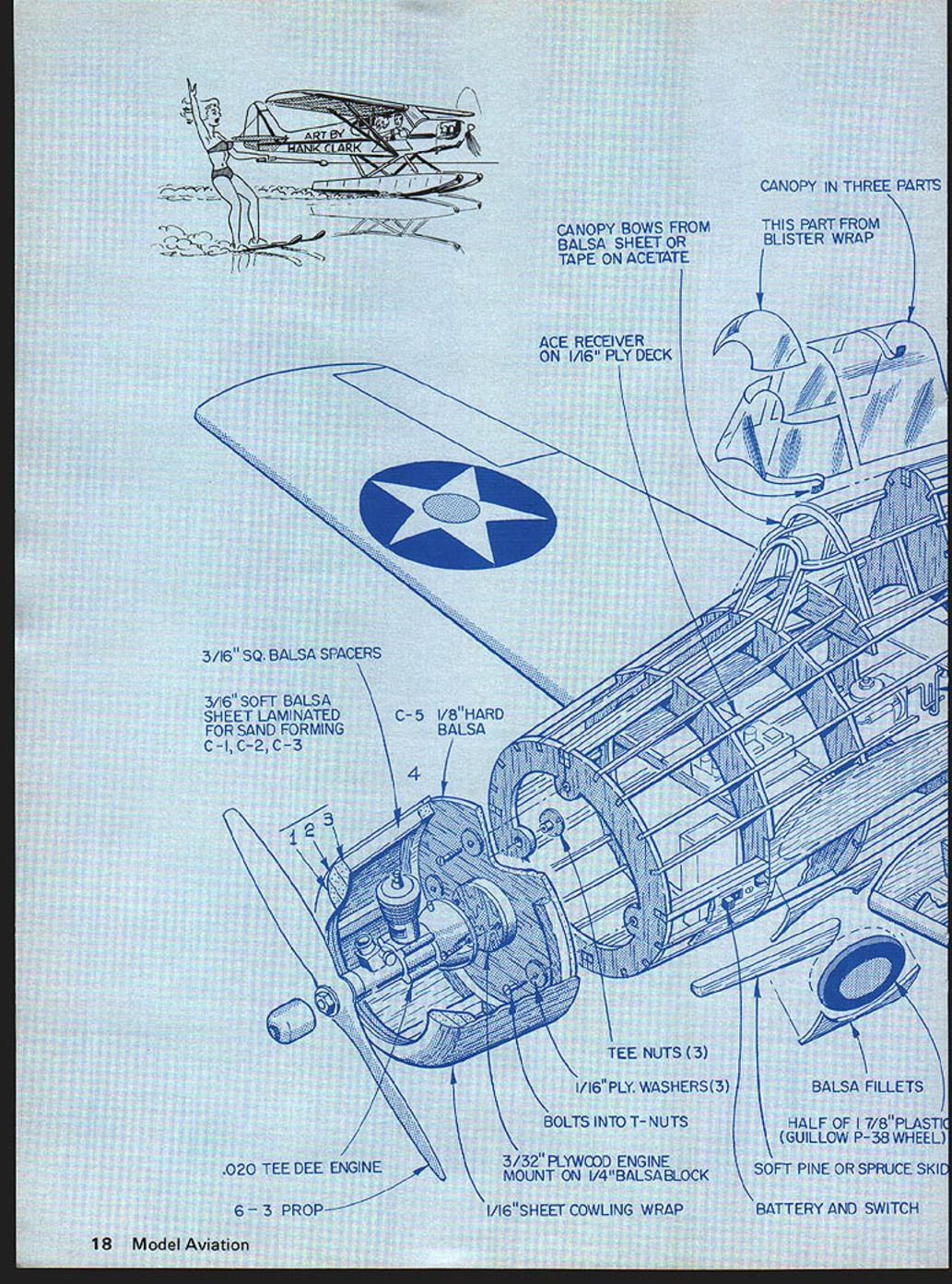
Cowl and landing gear wells:
- Build the cowl, temporarily attach it to the fuselage and sand until all contours are smooth and accurate.
- The actuator and torque rod are built into the fuselage.
- A plastic wheel from a Guillows P‑38 kit is just the right size; glue one half into each wheel well. Alternatively, cut a piece of 1/8" balsa to a 1‑7/8" diameter, shape and sand it to simulate the wheel.
Wing and tail:
- The wing and tail surfaces are ultra‑simple. The only firm, strong balsa member should be the root wing rib "A".
- Make sure the proper dihedral angle is built into both ribs. Sanding can correct minor errors, but it's easier to get it right initially.
Covering and Finishing
- After the frame is sanded smooth and to the proper contours, "scallop" the formers between each stringer by sanding with sandpaper wrapped around a pencil.
- Cover the fuselage with lightweight Silkspan. If you dampen the Silkspan first and work slowly, you can cover the entire fuselage with only 8–10 pieces.
- Pre‑dope the two rear stringers (from the canopy bottom to the tail post) to keep the tissue from pulling away when it shrinks.
- Cover wings and tail surfaces with Japanese tissue or lightweight Silkspan.
- Apply 5–6 coats of thinned clear butyrate dope on the fuselage to prepare it for color.
- Apply 3–4 coats of thinned, low‑shrink clear butyrate to seal tail surfaces and prevent warps.
- Apply one coat of color dope sparingly with an airbrush.
- Mask trim and spray; reproduce thin black pinstripes with 1/16" trim tape.
Assembly and Flight Preparation
- Make sure the wings go on straight, with proper and equal dihedral.
- Use only a couple of small spots of glue to attach the wing so it will pop off with minimum damage in a hard landing.
- Optionally, use a very lightweight wing plug‑in system (British style) instead of gluing the wings on—keep weight to a minimum if you do.
- Ensure all surfaces are warp‑free and the model balances on the spar.
- Use a 6‑3 black plastic prop and make the first test flights with the engine running slightly rich.
- If built according to the plans, the model should exhibit smooth, graceful flying characteristics. The cowled little engine sounds good too!
Final Trim and Flying Tips
- To achieve final longitudinal trim, add a small paper elevator tab or small pieces of clay ballast to obtain the desired climb and glide angles.
- In windy weather, place a lump of clay the size of a small marble in the cowl to increase penetration speed and reduce climb rate.
- In calm summer evenings remove the nose weight to enjoy an incredibly flat, slow glide. Modest lift will keep the little tub aloft indefinitely.
Conclusion
This model is very simple to build and rewarding to fly. If you follow the light construction, careful covering, and final trim suggestions, the little F4F will surprise you with its performance and appearance in the air.
I hope you have as much fun with your unique little F4F as we have had with ours.
Transcribed from original scans by AI. Minor OCR errors may remain.

