
Wildfire
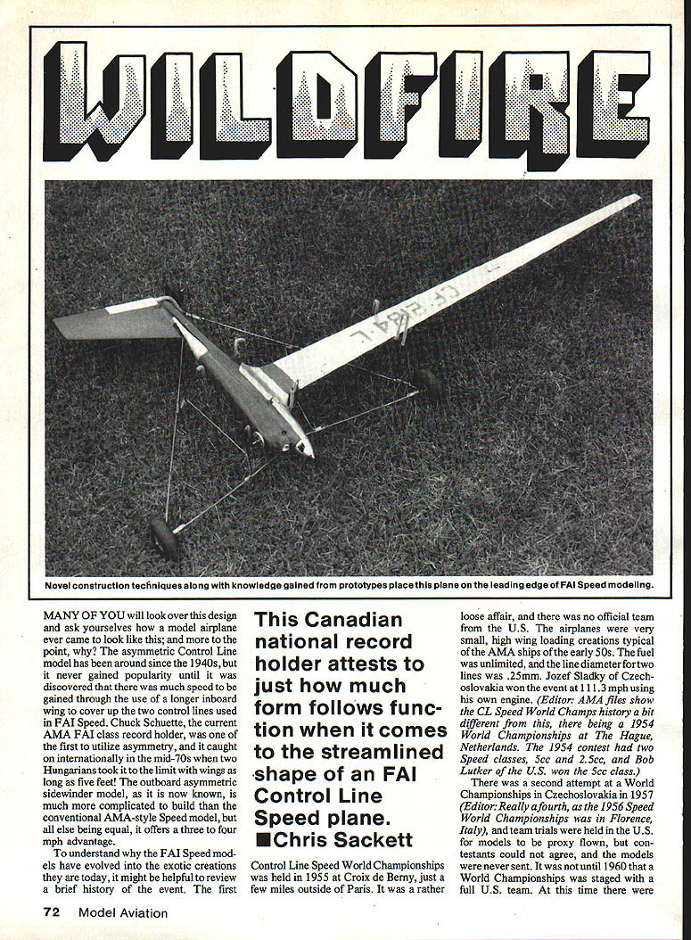
This Canadian national record holder attests to just how much form follows function when it comes to the streamlined shape of an FAI Control Line Speed plane. Photo: Chris Sackett
Many of you will look over this design and ask yourselves how a model airplane ever came to look like this — and more to the point, why? The asymmetric control line model has been around since the 1940s, but it never gained popularity until it was discovered that there was much speed to be gained through the use of a longer inboard wing to cover up the two control lines used in FAI Speed. Chuck Schuette, the current AMA FAI class record holder, was one of the first to utilize asymmetry, and it caught on internationally in the mid-70s when two Hungarians took it to the limit with wings as long as five feet! The outboard asymmetric sidewinder model, as it is now known, is much more complicated to build than the conventional AMA-style Speed model, but all else being equal, it offers a three to four mph advantage.
History
To understand why FAI Speed models have evolved into the exotic creations they are today, it helps to review a brief history of the event. The first Control Line Speed World Championships was held in 1955 at Croix de Berny, just outside Paris. It was a rather loose affair, and there was no official team from the U.S. The airplanes were very small, high wing-loading creations typical of AMA ships of the early ’50s. Fuel was unlimited, and the line diameter for two lines was 0.25 mm. Jozef Sladky of Czechoslovakia won the event at 111.3 mph using his own engine.
(Editor: AMA files show the CL Speed World Champs history a bit differently, noting a 1954 World Championships at The Hague, Netherlands. The 1954 contest had two Speed classes, 5 cc and 2.5 cc, and Bob Lutker of the U.S. won the 5 cc class.)
There was a second attempt at a World Championships in Czechoslovakia in 1957 (Editor: Really a fourth, as the 1956 Speed World Championships was in Florence, Italy), and team trials were held in the U.S. for models to be proxy-flown, but contestants could not agree and the models were never sent. It was not until 1960 that a full U.S. team was sent. At this time Model Aviation–specific wing loading requirements were still unlimited; monoline was acceptable although its use was protested by the Italians. Ugo Rossi of Italy won the event, actually whipping a model and narrowly beating 2nd-place finisher Bill Wisniewski at 146.142 mph.
The first time FAI-size models (77.47 sq in minimum) were used was at the 1962 meeting in Kiev. The straight fuel combination of methanol and castor oil was first introduced.
Asymmetry and the outboard layout
Chuck Schuette, father of asymmetric sidewinder designs, attended U.S. team trials. A conventional symmetrical model was flown; an asymmetric backup ship was used in practice. Europeans may have had first sight of the design at subsequent World Championships, and kinds of asymmetric designs turned up—upright, semi-asymmetric, true dog-leg inboard, or full asymmetric. Californians Chuck Schuette, Arnold Nelson, and Bob Spahr, among others, used the inboard design. A number of European speedsters, notably Italians, were experimenting with the outboard layout: pan inside, engine head outside—sidewinder flying concept. In the newer classes of Speed, including the 10 cc class, the basic outboard design is almost universally accepted now by competing nations in FAI Speed, except by some U.S. team members who continue use of the inboard version.
Prime reasons for utilizing the outboard setup include:
- Enabling a pure suction fuel-feed system.
- The pan inside makes room for a large hard tank on the centerline.
- The venturi engine can run a richer mixture during flight—somewhat like a mild form of pressure system.
- A simple, reliable model becomes airborne quite easily.
When I first decided on a design, the model borrowed many ideas and I added some of my own, hoping for the best of both worlds: a long inboard asymmetric wing and an outboard fully asymmetric layout; a model that was clean, with a slim fuselage, enclosed pipe, two-piece shell and easy maintenance. As I was designing the model, Jürgen Lenzen, a West German FAI flier, made available a perfect sidewinder speed pan with an integrated wing stub. I based the final design around the speed pan available from Jürgen Lenzen (Alfred-Dobbert-Str. 57, 5600 Wuppertal 2, West Germany). Twenty U.S. dollars will buy the right one.
Wing panels can be obtained from Sackett Products (P.O. Box 82294, North Burnaby, BC V5C 5P7; price about $30 U.S.). Rossi MK III speed pan available from Rossi Sales America (1325 Carol Dr., Memphis, TN 38116).
Construction
Speed pan and spar
Speed pan: Take exact dimensions from the front pan leading-edge wing setup. Speed pan stock comes with the root chord too wide; the leading-edge fillet must be cut back to accommodate a 3 in. wide wing. Dimension the leading-edge backplate and spinner carefully; you will have to grind inside the pan—be careful.
The dimension from the leading edge to the backplate of the spinner must be 3-3/4 in. You will have to grind the inside of the pan carefully to provide clearance for the Rossi .15 and to get the right location. Once satisfied, spray on some blue layout dye, mark the holes with a scribe, center punch, and drill and tap for 4-40 bolts 1/4 in. long.
Make up a jig to hold the pan at 90° while drilling, and make sure you don't drill through the casting. The next step is the installation of the spar and control system. The spar is formed from a piece of 3/16-in. aluminum bar stock, available at most metal shops. Type 7075 is nice but not necessary. My original was built from a piece of soft aluminum and is working fine. Cut a piece to 25 in., and taper it to 5/8 in. at the tip. Notice that it is not necessary for the spar to extend the full length. The material can be tapered in a lathe or simply filed by hand with a flat, top and bottom.
The spar is attached to the pan by tapping and threading 1/4-28. When tapping the pan, use a jig and press to assure accuracy. Test-fit the spar in the pan, and make sure everything lines up square. You may find it necessary to use small shims between the spar and pan to obtain the desired location. The wing alignment and incidence is set by the root fillet of the pan. The .010-in. wing skin slips over the fillet by 1/8 in. By filing the fillet you can set the exact root angle of attack. Using a wing with the correct twist, carve .090-in. positive incidence into the root of the pan.
Wing
Making these aluminum wings is simple, and once you've tried it you'll likely agree they are the quickest and easiest form of wing to make. The material is ALCLAD 2024 T3 with a thickness of .010 in. Many Speed fliers find this material at aircraft surplus stores or around airports that do service work. A sheet of 3 x 10 ft. will build many airplanes.
Determine the grain of the material first. It can be seen in the brushed effect the material possesses after being rolled at the mill. Be sure to lay out the wing with the grain running from the leading edge to the trailing edge; otherwise the wing will split when being folded. Use a spray-type layout dye on the aluminum surface, and mark the pattern carefully with a scribe.
Cut the wing with a No. 11 X-Acto blade, scoring the aluminum skin three or four times. It is not necessary to cut right through, as the material will break off cleanly when bent slightly. To achieve the airfoil section you must first bend the material flat in a sheet metal brake. Failing that, clamp it between two pieces of 2-in. angle iron in a large vise and use a third piece of straight angle iron to bend it to 90°. Remove it from the vise, and carefully bend it flat on a workbench using a couple planks of 3/4-in. plywood. Try to flatten the fold to around 1/16 in. for a nice sharp leading edge. Open up to 30° using a couple pieces of sheet metal and making sure it is straight and true.
Rough up the inside bonding surface of the wing with coarse sandpaper, and bond with Goodyear Plio-Bond. Clamp the wing between two pieces of 1-1/2-in. angle iron in a good-sized vise. Align it carefully until you get the desired airfoil section and a slight wash in the center. Clamp only the last 1/8 in. of the trailing edge to get a true symmetrical airfoil with no polywog. Clamp the full length of the wing with small C-clamps spaced every 6 in. and bake in a 350° oven for an hour and a half. An alternate method of bonding the wing is to use 3M 2216 gray epoxy and clamp in the same manner. Use as little as possible, as the weight will build up quickly.
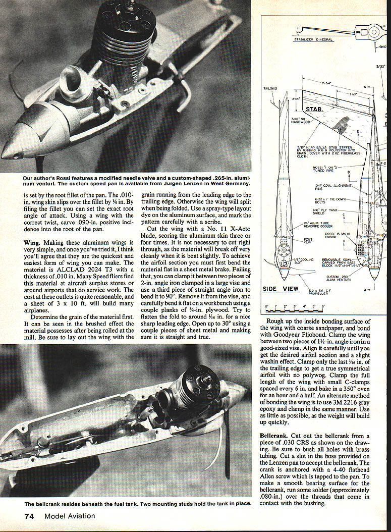
Bellcrank and control system
Cut out the bellcrank from a piece of .030 CRS as shown on the drawing. Be sure to bush all holes with brass tubing. Cut a slot in the boss provided on the Lenzen pan to accept the bellcrank. The crank is anchored with a 4-40 flathead Allen screw which is tapped to the pan. To make a smooth bearing surface for the bellcrank, run some solder (approximately .080 in.) over the threads that come in contact with the bushing.
Cut out the exit holes in the pan at the wing fillet area for the control lines. The lines are attached using small Monoline buttons hooked up to the .047-in. lead-outs. Finally, drill and tap two 6-32 holes for the tank mount.
Finish shaping the pan externally until you get the exact shape you want, then lap the engine mount surface with some emery paper and oil on a plate of sheet glass. Square all mating surfaces and true up, as much of the model's favorable flying characteristics will depend upon this.
Fuselage, crutch and cowl
The alignment of the entire model is based around the basswood crutch, so great care should be taken to get the stab mounting surface square to the thrust line. Start by laying out a centerline on both sides of the 5/8-in. crutch, and work solely from this reference line. Beginning with a square edge, locate and cut the stab mount area which should sit at a 7° dihedral angle 5/8 in. below the centerline of the crutch. It's easier to keep everything aligned if you work with a table saw, but you can cut by hand if you're accurate.
Lay the pan on the crutch, centering it and trace the outline of the fuselage, then rough-cut it to shape. Next take a piece of 1/4 x 1 x 10-in. medium balsa and tack-glue it into position for the tailpiece. The outer shape of the fuselage can then be sanded to the final shape, leaving only the area for the removable cowl unfinished.
Break the assembly apart, clean the pan, and mount the engine — taping up all openings to keep dirt out until finishing work is completed. Locate the outlet for the glow plug and rough-cut the cowl to clear the engine head.
Decide whether you wish to enclose the engine entirely in the fuselage or cut the cowl around it. I suggest you enclose the engine completely, as cutting the cowl away tends to weaken the crutch. To accomplish this, cut the lugs back 1/16 in. on the inside of the pan, leaving enough material on the crutch for adequate strength.
The cowl is formed from a blank of straight-grained balsa. I prefer a wood cowl over a fiberglass lay-up for better vibration-damping and strength. Start by cutting out the engine hole to a diameter 1/8 in. larger than the head. Use a circle cutter, then rough-clearance the inside to allow the cowl to accept the engine. Rough-shape the cowl to the approximate size shown, then tack-glue to the crutch, and blend it into the area of the fuselage. Break apart, install the pipe, and clearance the inside to an approximate thickness of 3/32 in. in the pipe area. The front should be as solid as possible.
Shape and sand in the cooling slot and venturi opening. As you may have noticed, the needle valve exits right on the cowl-crutch parting line. So as not to remove the needle valve when disassembling the model, the needle is shortened and modified — this will be covered later.
Stabilizer
It is important to build a light yet rigid stab assembly in order to get the center of gravity (CG) correct. Select a piece of stiff medium-hard 3/16-in. balsa, cut it to shape, and stiffen with 1/16-in. sq. spruce hardwood. Use slow-drying CyA and sand to a perfect symmetrical section, then cut out the elevator area. The elevator used on the original is an all-metal type which, when built correctly, resists failure from vibration and fatigue.
Solder up the frame as shown on the plan (I use Sta-Brite), and fold over a .010-in. aluminum skin. Cement in place with 3M 2216 epoxy.
The control horn is cut from a bit of .030-in. CRS and bushed for the .055-in. pushrod. Check that the height of the horn from axle to pushrod is exactly 9/16 in. on your model; it may be too sensitive. Carefully attach the elevator to the stab by gluing in the 3/32-in. tubing at the ends of the axle with slow-drying Hobbypoxy 2. To be sure you don't glue down the elevator, wax all areas with ChapStick where glue is not needed.
When dry, sand smooth, and stiffen the stab with a couple coats of thinned K&B polyester resin rubbed into the grain with a cloth. Three thin coats should be fine. Further stiffen the stab by covering with 2-oz. fiberglass cloth and resin. When dry, sand off any lumps and finish with two more coats of clear resin. Test-fit the stab to the fuselage. Hollow out enough material from the crutch to allow the control system to work smoothly, and hollow the tailpiece to a thickness of 5/16 in.
The pushrod must be installed on the elevator when attaching the stab to the crutch. Coat the control areas with ChapStick, and glue in place. The pushrod is a two-piece affair. To allow for disassembly, the back half is cut to approximate length. Install the two 1/16-in. ply formers and the two 3/32 x 1/2-in. pushrod guides. As shown on the drawing, the pushrod runs close to the inner edge of the fuselage. Bolt the whole assembly together to hand-fit the pushrod in its proper position. Fine adjustments can be made by resoldering the quick-links along the pushrod and by adjusting the threads.
Before gluing on the tailpiece, fuel-proof the tail section with a few coats of clear epoxy. When dry, check for smoothness of operation. This system must be free of slop, with little or no play; otherwise flying becomes erratic at high speeds. If there is any sloppiness, fix it now.
Carve and sand the pipe area to get a nice smooth seat for it to float on. (The pipe is attached to the engine from the head pipe so that it somewhat "floats" in the fuselage.) I use two small .031-in. wire hooks attached to the head pipe and around the front of the engine to a small spring. This is the only way to mount a tuned pipe if you are to avoid bending and breakage.
Test-fit the 5/16-in. tank shield by adjusting it to come as close as possible to the pipe without touching it. This is necessary because you will need all the room you can get for tank adjustment. When satisfied, glue in place. This tank shield prevents the fuel from becoming heated during flight.
Install .055-in. skids on the stab and on the fuselage. To keep the model in good alignment during hard wear and tear, glue in four alignment tabs made from 1/16-in. ply: two at the very front of the pan and two at the rear. To make a perfect fit, I like to mold them by mixing epoxy glue and finely chopped fiberglass cloth and dabbing it over the tabs. By waxing the pan you can now put the crutch-pan assembly together with the two mount bolts, and when dry it will break apart to a perfect-fitting pan with no play.
The cowl is mounted to the ship with a Prather DZUS clip and .047-in. wire hooked into the crutch.
Finish
I have found that the K&B Superpoxy system works best for providing a tough, durable, and fuel-proof finish. To begin, treat all bare wood surfaces with three coats of K&B polyester surfacing resin thinned about 50-50. Spray on a couple coats of K&B primer, sand smooth, and spray on your favorite color thinned 200%. To get a really smooth and shiny look, spray very fine coats. With practice you can achieve an outstanding wet look.
Fuel system
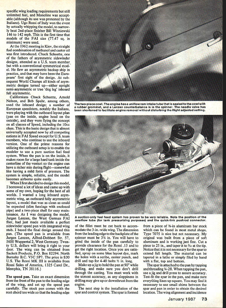
The fuel system most commonly used worldwide is the simple, pure suction method. Most other forms of fuel delivery have inherent inconsistencies, and inconsistency is the last thing you need with models that fly at tremendous speeds.
The tank, as shown on the drawing, must be no wider than 5/8 in. Otherwise the weight of the fuel from centrifugal force will make it difficult to get the engine lean enough for an optimum setting. All tubing is 5/16-in. brass, and you should cover the pickup tube in the tank with a fine screen to prevent air bubbles from entering the fuel line. The tank must float on the mounting studs and be totally free of any metal-to-metal contact with the pan. I achieve this by running large-size soft silicone tubing inside the 5/16-in. brass tube mounting brackets using small rubber grommets as caps on the ends.
The tank is located and adjusted using 6-32 aircraft nuts with washers on the mounting studs. Make sure to use a grommet over the fill line as it passes through the pan.
The venturi diameter will probably be determined on each individual model. Try to run as large an opening as possible while still having enough fuel draw to get off the ground. Start out with the stock Rossi unit or enlarge it to around .280 in. If desired, you can increase performance by adding an air-collecting funnel to the existing venturi to help supercharge the mix as it enters the crankcase. This can be achieved by gluing on a piece of aluminum tubing to the existing venturi flange with epoxy or by machining one from bar stock.
Engine
The Wildfire was built around the Rossi Mark III engine, but any good racing .15 will work. The OPS .15 is a good choice; so is the Cox (K&B). All of these engines will fit the spacious Lenzen pan. Start all rework by carefully disassembling the engine and inspecting the parts. To remove the bearings, heat in an oven at 300° then lightly tap the case and the bearings will fall out freely. Remove the casting steps in the main bypass areas of the crankcase with a Dremel tool, and then polish. The Rossi is a pretty good engine out of the box, so this is all the rework you should need for the case.
The latest Rossi pipe-timed engines are coming through with revised crank and liner timing figures. The crank should open at 35° after bottom dead center and close at 65° after top dead center. Crankwork starts by boring out the inside diameter to about .300 in. Radius the internal areas of fuel flow as much as possible and polish them smooth to prevent restriction, as well as the opening at the counterweight area shown on the drawing. To help atomize the incoming fuel charge, carefully cut in eight grooves around the crank hole at the back. It is a good idea to cover the crank pin with a small piece of brass tubing to protect it while grinding.
The latest Rossi Mark III pipe-timed engines are using ABC piston and liner sets with timing figures of 127° transfer timing and 194° for the exhaust. These are ideally suited for high rpm, small prop, alcohol-burning models of the FAI Speed type. Smooth out the corners on the transfer and boost ports for better fuel flow. These piston and liner assemblies are set up very close to optimum fits right out of the box, so there should be no need for any lapping or refitting.
The connecting rod can be streamlined to a symmetrical section to improve fuel flow. Do this with a small jeweler's file set using rounded files for the corners. Finish with No. 320 paper and polish. To ensure a good leak-proof seal between the liner and glow head, first lap the liner top flange on No. 400 paper on glass to remove any machine scores; then take an old glow head and lap the two together with a mild-cut polish to achieve a perfect fit.
Thoroughly clean the parts before reassembly. Scrub all parts with a toothbrush and methanol, then follow with an ultrasonic cleaner if available. Warm the case, drop in the bearings and crank, put on a prop, and tighten it up to seat the bearings; let it cool slowly, then test spin. The crank should spin freely for six or seven seconds and come to a stop at TDC (top dead center). If any binding occurs, warm the case again and tap lightly with a small wooden block to seat the bearings.
Assemble the rod, wrist pin, piston, and liner in the engine. While dry, turn it over and check for any binds or roughness. The engine should feel extremely free except for approximately .040 in. from TDC where the liner tapers into the piston. To set up head clearance, mark the deck height at TDC and compare this to the depth of your plugs. Use various shims to achieve a head clearance of .012 to .024 in. to start with. Later you can vary this dimension to attain maximum power from your particular combination.
The backplate is used stock, although some have had success shimming it out .040 to .050 in. with an aluminum spacer. This engine needs very little break-in—maybe 10 or 15 minutes of fast four-cycle hops. Bolt on a 7-3/4 prop cut to a 6-in. diameter, and run it fast and rich with no pipe for the first 10 minutes. If the needle holds steady, try a few peak runs and check rpm with a tachometer. You should read around 27,000 to 28,000 rpm for a good engine.
Attach a Rossi No. 2 pipe, bring it up to peak, and take a reading. The rpm should be around 34,000 to 35,000. An engine that will turn this rpm is good for the high 160s mph with the right prop. An engine that tacks 33,000 rpm will fly most FAI ships at about 158 mph — very competitive, and this is what most Rossis will turn right out of the box. You can postpone engine modifications for initial flights to get the feel of the airplane and do modifications later to note the difference.
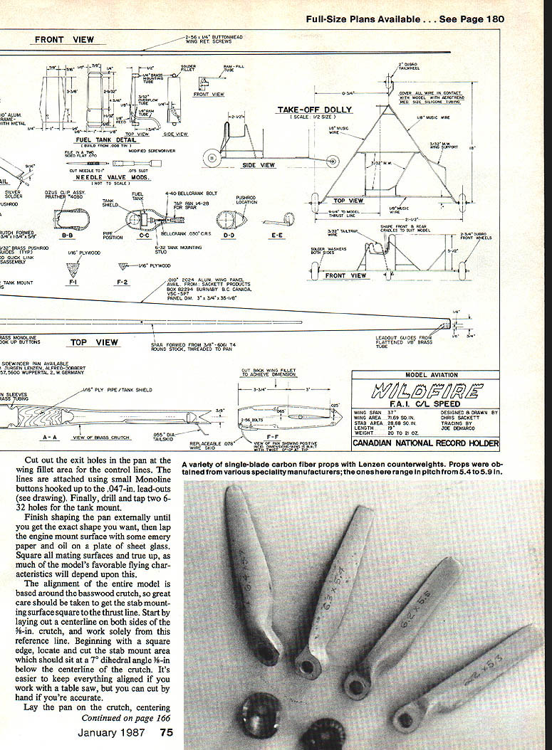
Propeller
Single-blade carbon fiber or, in some cases, hardwood props have been the accepted standard in FAI Speed flying since it was found that we go too fast on alcohol to reach high rpm with multi-blade setups. A number of companies produce these props in different styles and pitches. Try for a single-blade 6-in. diameter by 5.4 or 5-in. pitch for best results with a Mark III Rossi. Jürgen Lenzen has copies of the famous world-record-holding Hungarian props and will answer questions by mail. The prices are reasonable: about $5. Props are also available from Walt Perkins, Bill Hughes, and myself.
Dolly
Construct the dolly as shown — note that it, too, is asymmetric. This helps balance the model in the dolly and ensures good tracking and line tension during the critical takeoff period. Take time to build a very true and straight unit with all solder joints pre-soldered and wrapped with fine brass wire, then soldered with Sta-Brite or equivalent high-temperature solder. When making the dolly, slip some silicone tubing over areas that contact the airplane before the final assembly.
Flying
Check your model carefully to make sure everything is solid and operating 100%. Your two lines should be double-looped to prevent any chance of one of the ends opening up and causing a disaster. Two-line models are not quite as safe as the monoline AMA models that use very large wire diameters, which are easier to maintain. For safety’s sake, always inspect your lines before flying for kinks or other signs of wear.
For an approximate needle valve setting, strap on your standard bench-test prop, fill the tank, and fire up the engine. After a slight warm-up, the engine will hit the pipe dramatically. Adjust the needle for a full-peak run (slightly on the rich side), shut off the engine by placing your thumb over the back of the pipe, open the needle another one-quarter turn, and bolt on your flying prop. You’ll be ready for the first flight.
To make the fuel system work correctly you must understand that the tank position sets the needle in flight; the only needle adjustment you should make is to get the setting necessary to become airborne.
Fire up the engine and let it warm up for about 10 seconds, then raise the nose slightly to lean it out and pre-stage the pipe. Once the engine picks up on the lower stage of the pipe, you will have enough power to launch. Hold the elevator neutral until sufficient speed is attained to lift out of the dolly (usually one-half to three-quarters of a lap), then release the model. If the engine floods out rich in flight, move the needle out, or push the tank forward slightly (about 1/16 in.), and try again until a steady full-peaked run is achieved. If the engine runs lean, hunting on and off the pipe in the air, then move the tank back slightly and try again. With a small amount of fine tuning the optimum setting is easy to find and should be very consistent.
FAI Speed is a tremendous challenge. Just coming up with a good-flying airplane and reliable fuel system is half the battle. The Wildfire is a solid, good-flying ship that allows you to concentrate on other essentials such as the engine and propeller. If you build the model carefully and follow directions, it shouldn't be hard to become competitive and eventually join world-class competition. Give it a try.
Speed equipment suppliers / information
- North American Speed Society, P.O. Box 82294, Burnaby, B.C. V5C 5P7, Canada — Topflight: detailed information on all phases of CL Speed flying. Quarterly publication $15/year. Ed. Chris Sackett.
- Jürgen Lenzen, Alfred-Dobbert-Str. 57, 5600 Wuppertal 2, West Germany — Speed pan for the Wildfire Speed model; FAI single-blade props; metric-size lines.
- Sackett Products, P.O. Box 82294, Burnaby, B.C. V5C 5P7, Canada — Aluminum wing panels, carbon fiber props.
- Rossi Sales of America, 1325 Carol Dr., Memphis, TN 38116 — Rossi .15 MK III engines, Rossi .15 tuned pipes and glow heads.
- Shadow Racing, 1100 S.E. 28th St., Ocala, FL 32670 — FAI single-blade props of carbon fiber, and special prop-making epoxy.
- Kelly Props, P.O. Box 38, Western Springs, IL 60558 — Many sizes of FAI single-blade props in glass or graphite.
Transcribed from original scans by AI. Minor OCR errors may remain.

