
Wildman 60
Floyd E. Carter
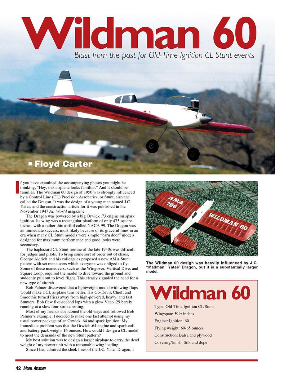
If you have examined the accompanying photos you might be thinking, "Hey, this airplane looks familiar." And it should be familiar. The Wildman 60 design of 1950 was strongly influenced by a Control Line (CL) Precision Aerobatics, or Stunt, airplane called the Dragon. It was the design of a young man named J.C. Yates, and the construction article for it was published in the November 1947 Air World magazine.
The Dragon was powered by a big Orwick .73 engine on spark ignition. Its wing was a rectangular planform of only 475 square inches, with a rather thin airfoil called NACA 99. The Dragon was an immediate success, most likely because of its graceful lines in an era when many CL Stunt models were simple "barn door" models designed for maximum performance and good looks were secondary.
The haphazard CL Stunt routine of the late 1940s was difficult for judges and pilots. To bring some sort of order out of chaos, George Aldrich and his colleagues proposed a new AMA Stunt pattern with set maneuvers which everyone was obliged to fly. Some of these maneuvers, such as the wingover, vertical dive, and square loop, required the model to dive toward the ground and suddenly pull out to level flight. This clearly signaled the need for a new type of aircraft.
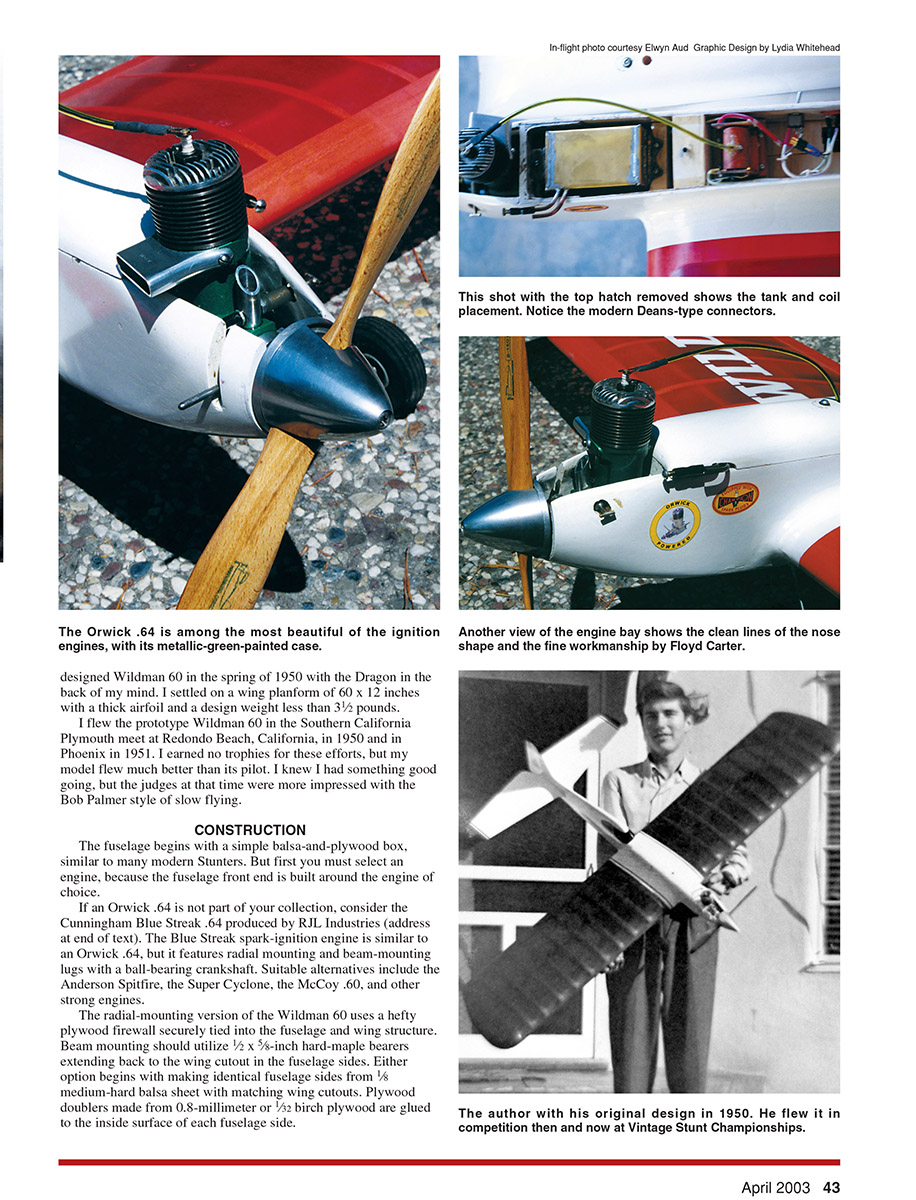
Bob Palmer discovered that a lightweight model with wing flaps would make a CL airplane turn better. His Go-Devil, Chief, and Smoothie turned fliers away from high-powered, heavy, and fast Stunters. Bob flew five-second laps with a glow Veco .29 barely running at a slow four-stroke setting. Most of my friends abandoned the old ways and followed Bob Palmer's example. I decided to make one last attempt using my usual power package of an Orwick .64 and spark ignition. My immediate problem was that the Orwick .64 engine and spark coil and battery pack weighed 16 ounces. How could I design a CL model to meet the demands of the new Stunt pattern?
My best solution was to design a larger airplane to carry the dead weight of my power unit with a reasonable wing loading. Since I had admired the sleek lines of the J.C. Yates Dragon, I designed the Wildman 60 in the spring of 1950 with the Dragon in the back of my mind. I settled on a wing planform of 60 x 12 inches with a thick airfoil and a design weight less than 3-1/2 pounds. I flew the prototype Wildman 60 in the Southern California Plymouth meet at Redondo Beach, California, in 1950 and in Phoenix in 1951. I earned no trophies for these efforts, but my model flew much better than its pilot. I knew I had something good going, but the judges at that time were more impressed with the Bob Palmer style of slow flying.
Construction
The fuselage begins with a simple balsa-and-plywood box, similar to many modern Stunters. But first you must select an engine, because the fuselage front end is built around the engine of choice. If an Orwick .64 is not part of your collection, consider the Cunningham Blue Streak .64 produced by RJL Industries (address at end of text). The Blue Streak spark-ignition engine is similar to an Orwick .64, but it features radial mounting and beam-mounting lugs with a ball-bearing crankshaft. Suitable alternatives include:
- Anderson Spitfire
- Super Cyclone
- McCoy .60
- Other strong .60-size engines
The radial-mounting version of the Wildman 60 uses a hefty plywood firewall securely tied into the fuselage and wing structure. Beam mounting should utilize 1/2 x 5/8-inch hard-maple bearers extending back to the wing cutout in the fuselage sides. Either option begins with making identical fuselage sides. Plywood doublers made from 0.8-millimeter or 1/32-inch birch plywood are glued to the inside surface of each fuselage side.
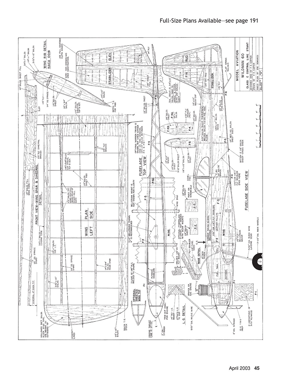
No primary article text appears on this page. The page is occupied by full-size plans and diagrams for the Wildman 60.
The radial-mount firewall F1 is epoxied in place with the straight top of the fuselage sides pinned to your building board. Use a T-square to ensure that the firewall will provide 0–1° engine thrust, and glue in former F2 to establish the slight taper, front to rear, of the fuselage sides. Further bracing of the radial-mount firewall to the fuselage sides is required, using spruce triangular pieces behind the firewall.
The plans show a molded plywood U-brace to further strengthen the firewall-fuselage interface, but this brace requires building a male/female panel-line fixture to bend and laminate the thin sheets of plywood to make the U-brace. An alternate and satisfactory method is to lay in fiberglass cloth and epoxy to strengthen this joint.
For beam mounting, drill the maple engine bearers and install T-nuts. Bolt the engine to the engine bearers, keeping the bearers parallel. This establishes the width of firewall F1, which can be 1/8-inch birch plywood for this option. If F1 turns out to be different from what is shown on the plans, the remainder of the fuselage formers must also be adjusted to keep the fuselage sides parallel back to the end of the engine bearers and to establish the required curve of the fuselage sides. If a smoother taper in the fuselage top view is desired, the engine bearers can be narrowed aft of the firewall.
With the firewall epoxied in place and a balsa fill-in between the engine bearers to keep them parallel, this engine-mount assembly can be epoxied to the plywood of the fuselage sides. It is easier to epoxy the engine-mount assembly to the fuselage one side at a time. This gives you room to see that the maple engine bearers are parallel with the top of the fuselage and to use weights on the engine-mount assembly to ensure good contact with the fuselage side. Epoxy the second fuselage side in place with the fuselage sides turned upside down on your flat building surface.
With the fuselage still mounted upside-down on the building board, glue in place the remainder of the fuselage spacers, formers, and doublers, and pull the fuselage together at the tail post. Take care to keep the fuselage curve symmetrical and without any twist.
Build the fuselage turtledeck and top block. The turtledeck on the 1993 Wildman 60 was made from two layers of 1/32-inch balsa sheet laminated on a pine mold with a layer of silkspan paper between. This requires building a mold, but the result is light and strong. Conventional construction is shown on the plans.
The top hatch must be removable for access to the spark-ignition components and fuel tank. The removable hatch may also include the simulated "cockpit," or the cockpit can be permanently glued to the fuselage with the hatch separation line just ahead of the cockpit. Either option will provide engine access to the interior.
Notice that the fuselage gets no torsional support from the top block. The fuselage sides will be firmly anchored to the wing center sheeting to stiffen the fuselage in the absence of a glued-on top block.
Tail Group
The prototype Wildman 60 had light 1/16-inch balsa covering over the built-up tail. The 1993 model did not use balsa covering. The tail group is a 3/8 x 1-1/2-inch balsa outline. Double-glue the pieces together and install 3/8-inch gussets at all corners (not shown on the plans).
Cloth "over-and-under" hinges are authentic and also seal the hinge gap for better control response. Rayon taffeta material works best. The tail group is plenty strong with silk or heavy silkspan covering.
The long tail moment and generous stabilizer area provide authoritative pitch control. Therefore, your bellcrank and elevator horn geometry should be planned for not more than 30° of elevator movement up and down.
Wing
Build the spars with doublers first. Draw your own dihedral template on a large piece of plywood. Both wing panels are the same length. Assemble the main spar over your dihedral template, and glue on the one-piece filler of 1/4-inch balsa and the plywood doublers. Build the rear spar over the main spar to duplicate the dihedral angle and prevent a crooked wing. Cut out the slot for the bellcrank to move through the main spar now, before you forget.
Make a wing-rib template of plywood or aluminum so that all ribs will be cut and sanded exactly the same. If you use a wing fixture featuring 1/4-inch-diameter steel rods, include these holes on the wing-rib template. The 1/4-inch holes will be used to align the wing on the fixture, but also pay attention to the leading-edge and trailing-edge lineup, in case the wing-rib holes are not quite accurate.
With the basic wing frame completed, install the plywood bellcrank mount, bellcrank, pushrod wire, and leadouts. The wing center-section sheeting on the top of the wing should be joined at the centerline between panels, and it should be reinforced with silk and epoxy. The bottom center-section sheeting of 3-inch-wide balsa should be in continuous pieces across the fuselage centerline wherever possible.
The wingtips on the prototype were balsa blocks, but a built-up and sheet-covered tip is suitable, less expensive, and easier. An extra rib that is slightly smaller than the airfoil ribs must be installed to provide a two-step "break" in the tip design. An outboard wing weight box is recommended, but adjustable line guides are not required if leadout position is per the plans.
Final Assembly
Assemble the wing and tail group to the fuselage, taking great care to keep everything symmetrical and square. It is important that the wing/fuselage joint be secure. If the wing does not fit the fuselage wing cutout exactly, use scrap balsa packing to get good contact.
Lash the landing-gear wire to its plywood mount using copper wire and epoxy. This is plenty strong. Install the landing-gear mount by cutting out enough wing bottom center planking to insert the plywood gear mount. It is important to epoxy the landing-gear mount to the fuselage sides and to the bellcrank plywood mount. This ties everything together.
Leather triangular pattern-makers' fillets are no longer generally available. A good substitute is very soft triangular balsa, wetted in ammonia, heated, and carefully bent to shape. After gluing in place, sand the fillets to a concave shape using sandpaper wrapped around a short length of birch dowel. The epoxy putty normally used these days for fillets will be heavy if laid down to the required thickness. Besides, it is difficult to get a smooth fillet with epoxy. The model will fly better if the fillets are carefully shaped and taped for a finished appearance. Models have a rather crude look without these generous wing fillets.
Finishing
Silk covering is my material of choice. This wing is plenty strong for G forces, but it depends on the covering for torsional stability. Silk or heavy silkspan covering is necessary.
Center of Gravity (CG)
With the model assembled and covered, and with most of the paint applied, the CG can be adjusted by positioning the flight battery. Hopefully this step can eliminate the addition of lead for balance. The 1950 model had the battery aft of the CG. The 1993 model has the flight battery installed under the fuel tank. One never knows until the last minute!
Spark Ignition
There is no need to fear spark ignition! Modern electronics and Ni-Cd flight cells all but eliminate spark-ignition problems. I use the transistorized spark coil made by Aero Ply Research Co. (address at end of text). As a bonus, the transistorized spark-ignition units reduce the current flowing through the engine timer points to 1/50 ampere, with no sparking. This means that your engine points will never burn out or wear out. I typically start an ignition engine in less time than most people can start a Fox .35 or an O.S. engine.
I use a homemade, rectangular fuel tank made from K & S tin sheet stock. It is 1.9 inches wide, 3 inches long, and 1 inch high, with uniflow venting, giving nearly three ounces capacity. This will run the Orwick .64 for roughly seven minutes on fuel consisting of three parts Coleman lantern fuel and one part Castrol 70 motorcycle oil. Be sure to time your engine's fuel consumption to get the correct tank volume.
I prefer rectangular fuel tanks because they provide maximum volume in the space available. In addition, a rectangular tank takes approximately three laps of coughing and wheezing before the engine stops completely. I will not get caught in an overhead maneuver with a suddenly dead engine. It is a good idea to make your fuel tank removable for maintenance. Solder brackets to the tank, and secure the tank with small wood screws.
Flying
This model flies best on 66-foot braided lines of .018-inch diameter. With the long wing, the radius of flight is nearly 70 feet.
Floyd E. Carter 2029 Crist Dr. Los Altos, CA 94024
Sources
- Cunningham Blue Streak engine:
RJL Industries Box 5 Sierra Madre, CA 91025
- Spark ignition:
Aero Ply Research Co. 2029 Crist Dr. Los Altos, CA 94024
Transcribed from original scans by AI. Minor OCR errors may remain.

