
Wiley Post Biplane
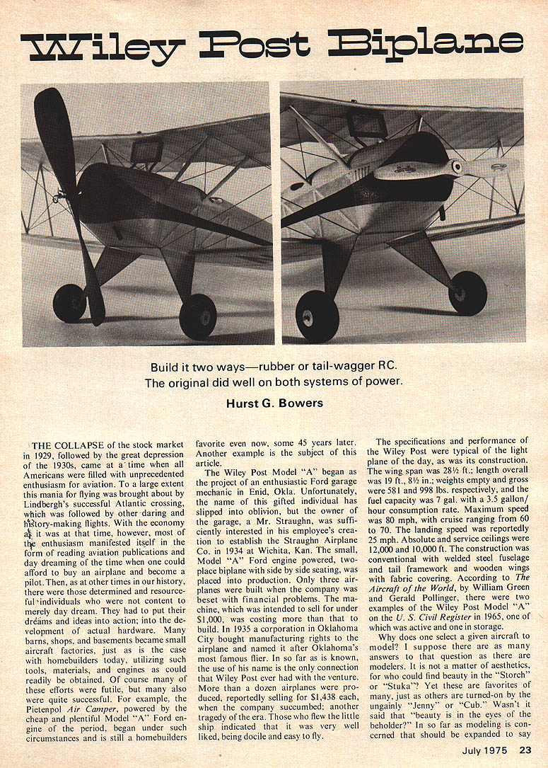
Build it two ways—rubber or tail-wagger RC. The original did well on both systems of power.
Hurst G. Bowers
THE COLLAPSE of the stock market in 1929, followed by the great depression of the 1930s, came at a time when all Americans were filled with unprecedented enthusiasm for aviation. To a large extent this mania for flying was brought about by Lindbergh's successful Atlantic crossing, which was followed by other daring and history-making flights. With the economy as it was at that time, however, most of the enthusiasm manifested itself in the form of reading aviation publications and day dreaming of the time when one could afford to buy an airplane and become a pilot. Then, as at other times in our history, there were those determined and resourceful individuals who were not content to merely day dream. They had to put their dreams and ideas into action; into the development of actual hardware. Many barns, shops, and basements became small aircraft factories, just as is the case with homebuilders today, utilizing such tools, materials, and engines as could readily be obtained. Of course many of these efforts were futile, but many also were quite successful. For example, the Pietenpol Air Camper, powered by the cheap and plentiful Model "A" Ford engine of the period, began under such circumstances and is still a homebuilder's favorite even now, some 45 years later. Another example is the subject of this article.
The Wiley Post Model "A" began as the project of an enthusiastic Ford garage mechanic in Enid, Okla. Unfortunately, the name of this gifted individual has slipped into oblivion, but the owner of the garage, a Mr. Straughn, was sufficiently interested in his employee's creation to establish the Straughn Airplane Co. in 1934 at Wichita, Kan. The small Model "A" Ford engine powered, two-place biplane with side-by-side seating, was placed into production. Only three airplanes were built when the company was beset with financial problems. The machine which was intended to sell for under $1,000, was costing more than that to build. In 1935 a corporation in Oklahoma City bought manufacturing rights to the airplane and named it after Oklahoma's most famous flier. In so far as is known, the use of his name is the only connection that Wiley Post ever had with the venture. More than a dozen airplanes were produced, reportedly selling for $1,438 each, but the company succumbed; another tragedy of the era. Those who flew the little ship indicated that it was very well liked, being docile and easy to fly.
The specifications and performance of the Wiley Post were typical of the light plane of the day, as was its construction. The wing span was 28 1/2 ft.; length overall was 19 ft., 8 1/2 in.; weights empty and gross were 581 and 998 lbs. respectively, and the fuel capacity was 7 gal. with a 3.5 gallon/hour consumption rate. Maximum speed was 80 mph, with cruise ranging from 60 to 70. The landing speed was reportedly 25 mph. Absolute and service ceilings were 12,000 and 10,000 ft. The construction was conventional with welded steel fuselage and tail framework and wooden wings with fabric covering. According to Aircraft of the World, by William Green and Gerald Pollinger, there were two examples of the Wiley Post Model "A" on the U. S. Civil Register in 1965, one of which was active and one in storage.
Why does one select a given aircraft to model? I suppose there are as many answers to that question as there are modelers. It is not a matter of aesthetics, for who could find beauty in the "Storch" or "Stuka"? Yet these are favorites of many, just as others are turned on by the ungainly "Jenny" or "Cub." Wasn't it said that "beauty is in the eyes of the beholder"? In so far as modeling is concerned that should be expanded to say "beauty is in the eyes of the beholder, at a given time, and for a given purpose." For that reason I selected the Wiley Post for an indoor rubber-powered project. It turned out to be a beautiful model, but our indoor flying site simply didn't do it justice. In spite of all my adjusting, this seemed to be a "right hand turn" model that liked big circles.
I resigned myself to the fact that it was best suited for outdoors. However, during a careful check of alignment I discovered the problem — a slight amount more wash-in on the top wing panels than the other. With this corrected the model flies nicely but I still feel that it is better suited for outdoor flying on those lazy, calm summer evenings. Since the weight of the Cox .020 Pee Wee engine very nearly equals the weight of the propeller and rubber why not make this a power job? Better yet, the little ACE "Baby" pulse R/C unit which weighs only slightly over three ounces will save lots of long chases to retrieve the model.
Look at the figures; the wing area is 187 sq. in., or 1.3 sq. ft., while the model weight, complete with engine and radio, can be easily held to 10 oz. or under. This gives a wing loading of 8 oz. or 1/2 lb. per sq. ft. In our experience with the small "schoolyard scale" R/C models which are becoming so popular, we have found this wing loading to be perfect. Needless to say, this little model has unlimited possibilities and, in keeping with the original concept of the prototype, 42 years ago, it is cheap to build and fly in either mode. Best of all, you don't have to burn 10 gal. of gasoline in your car going out to a suitable flying field — just walk over to the local school yard and "let her rip."
Construction
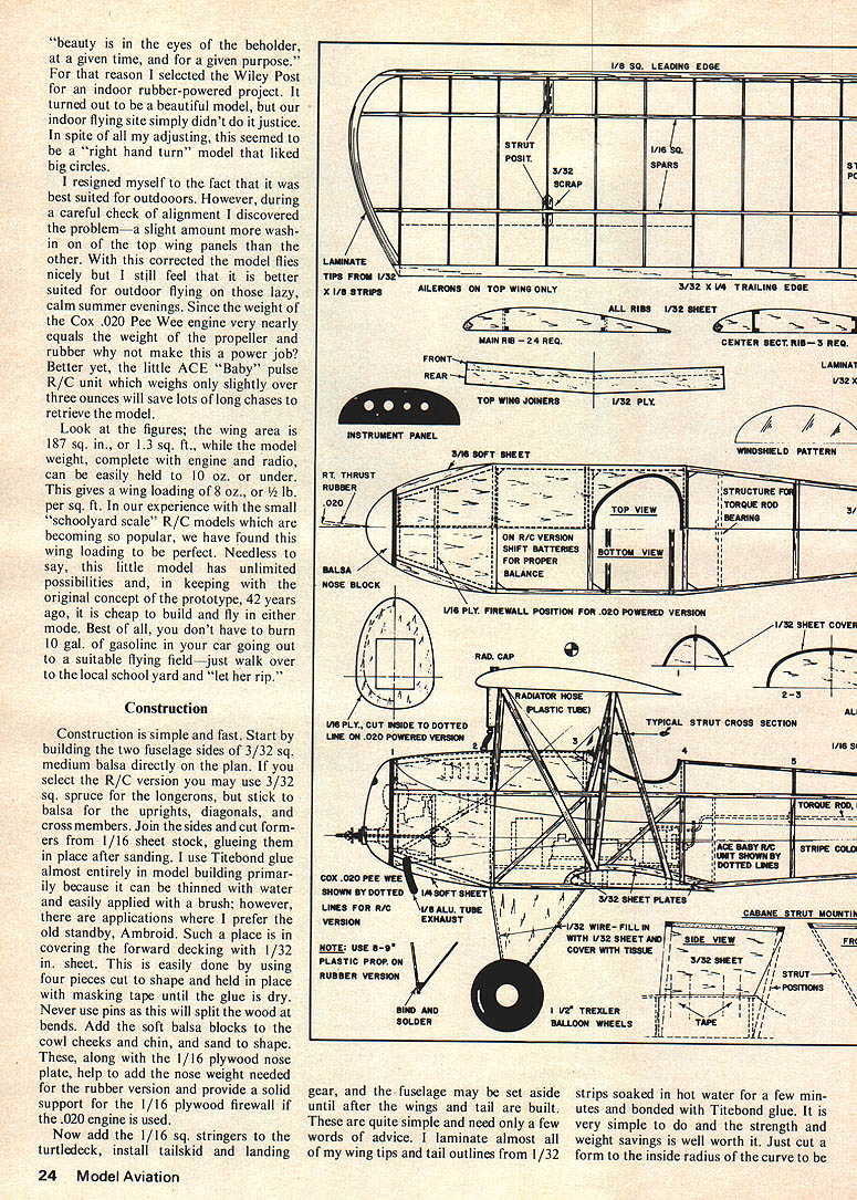
Construction is simple and fast. Start by building the two fuselage sides of 3/32 sq. medium balsa directly on the plan. If you select the R/C version you may use 3/32 sq. spruce for the longerons, but stick to balsa for the uprights, diagonals, and cross members. Join the sides and cut formers from 1/16 sheet stock, gluing them in place after sanding. I use Titebond glue almost entirely in model building primarily because it can be thinned with water and easily applied with a brush; however, there are applications where I prefer the old standby, Ambroid. Such a place is in covering the forward decking with 1/32 in. sheet. This is easily done by using four pieces cut to shape and held in place with masking tape until the glue is dry. Never use pins as this will split the wood at bends. Add the soft balsa blocks to the cowl cheeks and chin, and sand to shape. These, along with the 1/16 plywood nose plate, help to add the nose weight needed for the rubber version and provide a solid support for the 1/16 plywood firewall if the .020 engine is used.
Now add the 1/16 sq. stringers to the turtledeck, install tailskid and landing gear, and the fuselage may be set aside until after the wings and tail are built. These are quite simple and need only a few words of advice. I laminate almost all of my wing tips and tail outlines from 1/32 strips soaked in hot water for a few minutes and bonded with Titebond glue. It is very simple to do and the strength and weight savings is well worth it. Just cut a form to the inside radius of the curve to constructed, sand it and rub it with soap or a candle along the edge to prevent sticking. Then take the wet strips, apply the glue, and stack them one on the other.
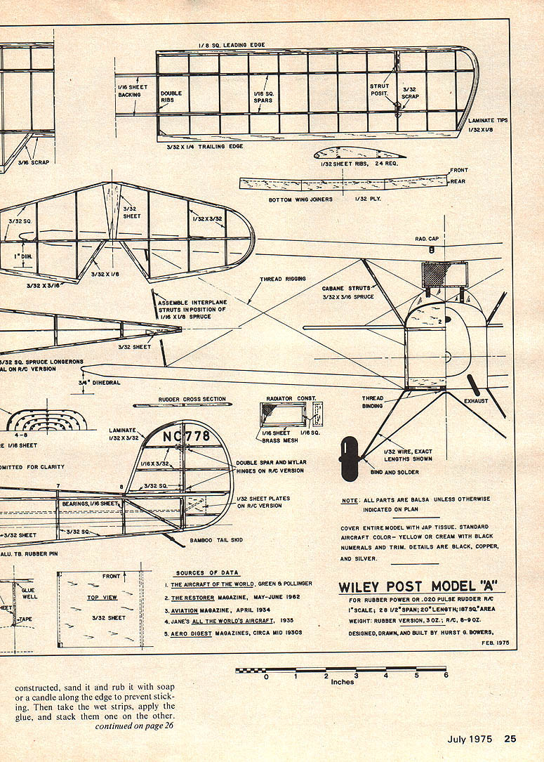
WILEY POST MODEL "A"
FOR RUBBER POWER OR .020 PULSE RUDDER R/C
1" SCALE; 28 1/2" SPAN; 20" LENGTH; 18.7 SQ. AREA
WEIGHT: RUBBER VERSION, 3 OZ.; R/C, 6-8 OZ.
DESIGNED, DRAWN, AND BUILT BY HURST G. BOWERS FEB. 1975
NOTE: ALL PARTS ARE BALSA UNLESS OTHERWISE INDICATED ON PLAN
COVER ENTIRE MODEL WITH JAP TISSUE. STANDARD AIRCRAFT COLOR - YELLOW OR CREAM WITH BLACK NUMERALS AND TRIM. DETAILS ARE BLACK, COPPER, AND SILVER.
SOURCES OF DATA
- THE AIRCRAFT OF THE WORLD, GREEN & POLLINGER
- THE RESTORER MAGAZINE, MAY-JUNE 1962
- AVIATION MAGAZINE, APRIL 1934
- JANE'S ALL THE WORLD'S AIRCRAFT, 1938
- AERO DIGEST MAGAZINES, CIRCA MID 1930S
Hold them in place around the edge of the form with masking tape until dry, then carefully remove the form. I usually let them dry overnight. Once you try this method I'm sure you won't use any other again.
If you select the R/C version be sure to use two 3/32 sq. spars on the rudder so that it may be separated from, and hinged to the fin using Mylar strip hinges held in place with a drop of epoxy. When you have put the 1/32 sheet plates on each side of the rudder over the location where the torque arm actuates, drill a 1/16 in. hole in the spar so as to permit free and loose insertion of the arm into the rudder. Let me emphasize that this must be loose and free, but not sloppy. When you build the wings don't forget that the scrap balsa strut seats should be on the top side of the bottom wings and on the bottom sides of the top wings; confusing, isn't it?
Now that all the framework is completed, sand it carefully and cover the model. If you select the R/C version be sure you leave access through the bottom to install the radio equipment, along with provisions for charging, etc. I used yellow Jap tissue which is beautiful, and when doped with three or four coats of Sig "Lite Coat" low-shrink clear dope, it is strong and entirely adequate for either rubber or light R/C models. Use black tissue for the wing and tail numerals, however, a picture that I saw of the prototype did not have them. The construction of details is next, and the cockpit. The radiator screen is light brass mesh, but if this isn't available use a piece of your handkerchief or shirttail and paint it gold. It looks just as good. Make the hoses and cockpit padding of black plastic tubing or wire insulation, and the exhaust pipe from 1/8 in. aluminum tubing.
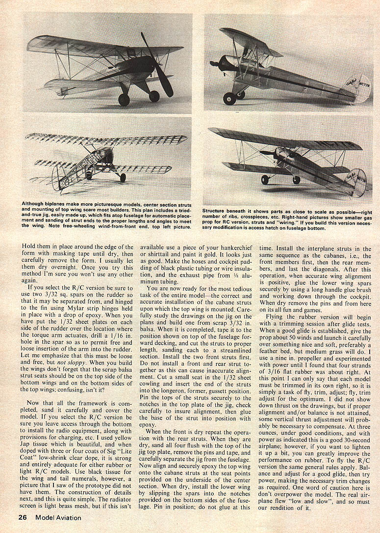
You are now ready for the most tedious task of the entire model—the correct and accurate installation of the cabane struts upon which the top wing is mounted. Carefully study the drawings on the jig on the plans and build one from scrap 3/32 in. balsa. When it is completed, tape it to the position shown on top of the fuselage forward decking, and cut the struts to proper length, sanding each to a streamlined section. Install the two front struts first. Do not install a front and rear strut together as this can cause inaccurate alignment. Cut a small seat in the 1/32 sheet cowling and insert the end of the struts into the longeron, former, gusset position. Pin the tops of the struts securely to the notches in the top plate of the jig, check carefully to insure alignment, then glue the base of the strut into position with epoxy.
When the front is dry repeat the operation with the rear struts. When they are dry, sand all four flush with the top of the jig top plate, remove the pins and tape, and carefully separate the jig from the fuselage. Now align and securely epoxy the top wing onto the cabane struts at the seat points provided on the underside of the center section. When dry, install the lower wing by slipping the spars into the notches provided on the bottom sides of the fuselage. Pin in position; do not glue at this time. Install the interplane struts in the same sequence as the cabanes, i.e., front members first, then the rear members, and last the diagonals. After this operation, when accurate wing alignment is positive, glue the lower wing spars securely by using a long handle glue brush and working down through the cockpit. When dry remove the pins and from here on it's all fun and games.
Flying the rubber version will begin with a trimming session after glide tests. When a good glide is established, give the prop about 50 winds and launch it carefully over something nice and soft, preferably a feather bed, but medium grass will do. I use a 9 in. propeller and experimented with power until I found that four strands of 3/16 in. flat rubber was about right. At this point I can only say that each model must be trimmed in its own right, so it is simply a task of fly, trim, adjust; fly, trim, adjust for longer time. If you do not find optimum trim on the drawings, but if proper alignment and/or balance is not attained, some vertical thrust adjustment may be necessary to compensate. At three ounces, under good conditions, and with power as indicated this is a good 30-second airplane; however, if you want to light it up a bit, you can greatly improve the performance on rubber. To fly the R/C version the same general rules apply. Balance and adjust for a good glide, then try to add throttle power carefully. The real airplane flew "low and slow", and so must our rendition of it.
Best don't have to burn 10 gal. of gasoline in the car going out to a suitable flying field — just walk over to the local school yard and let 'er rip.
CONSTRUCTION
Construction is simple and fast. Start building two fuselage sides, 3/32 sq., medium balsa, directly on the plan. If you select the R/C version you may use 3/32 sq. spruce longerons. Stick balsa uprights, diagonals and cross members. Join sides, cut formers from 1/16 in. sheet stock and glue in place after sanding.
Transcribed from original scans by AI. Minor OCR errors may remain.

