
Willit
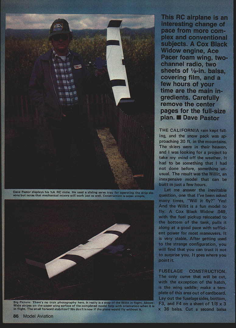
The Willit is an inexpensive RC airplane that can be built in just a few hours. It’s an unusual, fun-to-fly configuration that responds well in the air. A Cox Black Widow .049 (with the fuel pickup relocated to the bottom of the tank), an Ace Pacer foam wing, a two-channel radio, and basic building materials are all you need.
- Main materials:
- Cox Black Widow .049 engine
- Ace Pacer foam wing kit
- Two-channel radio and servos
- Two sheets of 1/8 x 3 x 36 in. balsa
- 1/8-in. plywood (1/8 in. ply)
- 1/8-in. sq. balsa stock
- Covering film (lightweight heat-shrink recommended)
- 5-in. dowel for wing mounting
- Two 3/8 x 3/8 x 3/4 in. hardwood blocks (for wing hold-down screws)
- Covering and fuelproofing materials
- Epoxy (5-minute), white glue
Carefully remove the center pages of the original plan for full-size patterns.
Fuselage Construction
- Templates and stock
- Make a cardboard template for the only curved cut (the wing saddle). The hatch is the other curved cut.
- Lay out the fuselage sides, bottom, F3, and F4 on a sheet of 1/8 x 3 x 36 in. balsa.
- Cut a second sheet of that size in half and edge-glue it to make a 1/8 x 6 x 18 in. piece. Use this for the top hatch, vertical stabilizers, and wing-saddle doublers; orient the grain properly.
- The leftover from the 6-in. piece will be used for the canard doublers and the cross-grain front bottom fuselage sheeting. Do not trace or cut the canard hatch yet.
- Cut parts
- From a piece of 1/8-in. plywood, cut F1, F2, and the hatch hold-down pieces.
- Cut two pieces of 1/8-in. sq. balsa for the fuselage bottom corner fillers.
- Cut two 3/8 x 3/8 x 3/4 in. hardwood blocks to receive the wing hold-down screws.
- Assemble the fuselage
- Glue the 1/8-in. sq. fillers to the fuselage bottom and glue the wing-saddle doublers to the fuselage sides.
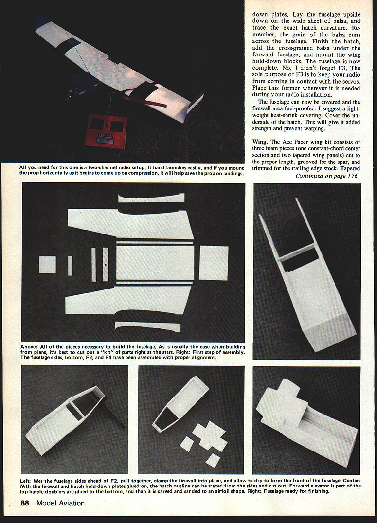
- When dry, glue the fuselage sides to the bottom and install F2 and F4 between the sides. Doing this in one step helps ensure correct alignment.
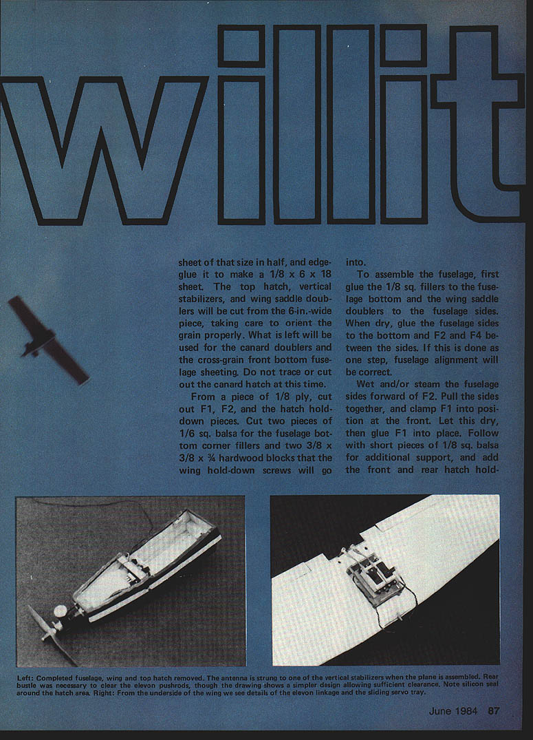
- Wet or steam the fuselage sides forward of F2, pull the sides together, clamp F1 into position at the front, let dry, then glue F1 into place.
- Add short pieces of 1/8-in. sq. balsa for additional support and add the front and rear hatch hold-down plates.
- Lay the fuselage upside down on the wide sheet of balsa and trace the exact hatch curvature (grain should run across the fuselage). Finish the hatch and add cross‑grained balsa under the forward fuselage mount and wing hold-down blocks.
- Fuel-proof the firewall area and use a light-weight heat-shrink covering. Cover the underside of the hatch for added strength and to prevent warping.
Note: F3’s sole purpose is to keep the radio and receiver cables from contacting the servos. Place this former wherever needed during radio installation.
Wing
- The Ace Pacer wing kit consists of three foam pieces: a constant-chord center section and two tapered wing panels. Cut the pieces to proper length, groove them for the spar, and trim for the trailing-edge stock. Aileron stock is also included with the kit.
- Assemble the foam wing
- Join the foam wing pieces with 5-minute epoxy.
- Using white glue, attach the spar and the trailing-edge stock. When dry, trim the trailing-edge stock flush with the wing panels.
- Mounting the wing
- Place the assembled wing on the fuselage and check alignment. Hold it in place with rubber bands.
- Insert a 1/8-in. drill bit through the hole in F2 and, turning it by hand, drill a hole into the foam wing for the wing dowel.
- Cut a 5-in. dowel and check fit against the hole in F2. When it fits, epoxy the dowel into the foam wing.
- While the epoxy cures, align the wing in place on the fuselage and complete final mounting.
- Covering
- Cover the wing with a low-temperature covering film directly over the foam.
- Cover the rudders and attach them.
Controls and Linkages
- Mount the servos and hook up the radio. Use the straightest pushrods possible.
- To prevent the wire from breaking out of the small aileron stock, add a small piece of 1/32-in. plywood, top and bottom, at each elbow where the hole is drilled.
- Use your preferred hinging technique for ailerons and elevators.
- Recommended control throws:
- Elevator: ±1/4 in.
- Ailerons: ±3/16 in.
- Check that all combinations of elevator and aileron commands are free of binding.
Final Assembly and Checkout
- Glue F3 as far to the rear as practical to keep the receiver and cables from fouling the servos.
- Mount the servos, receiver, battery, and secure them with lightweight foam as needed.
- Screw on the engine and fuel-proof the firewall area.
- Mount the wing and verify that the aileron horns do not contact the rear of the fuselage at full-up elevator and full aileron deflection.
- Check the center of gravity (CG) and move the radio gear as necessary to achieve proper balance. Avoid using ballast unless absolutely necessary—adding 1 oz. is more than a 5% increase in total model weight.
- Perform a final control check and then conduct a test flight.
Flight characteristics are similar to a normally configured model. The Willit is very stable and, after you get used to the unusual configuration, will not surprise you in flight. Be prepared for an audience—its appearance in the air attracts attention and praise for your piloting skill from those who assume flying wings are touchy.
Transcribed from original scans by AI. Minor OCR errors may remain.

