
WINDLORD
A high-performance flying wing sailplane that has proved competitive to conventional craft. — Ken Bates
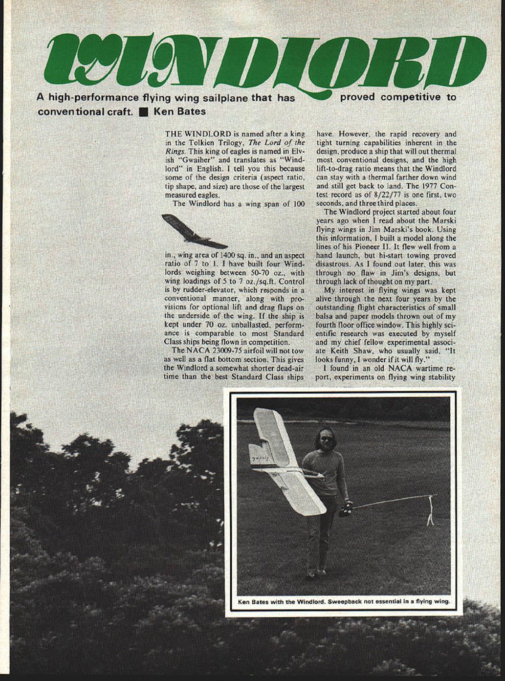
THE WINDLORD is named after a king in the Tolkien Trilogy, The Lord of the Rings. This king of eagles is named in Elvish "Gwaiher" and translates as "Windlord" in English. I tell you this because some of the design criteria (aspect ratio, tip shape, and size) are those of the largest measured eagles.
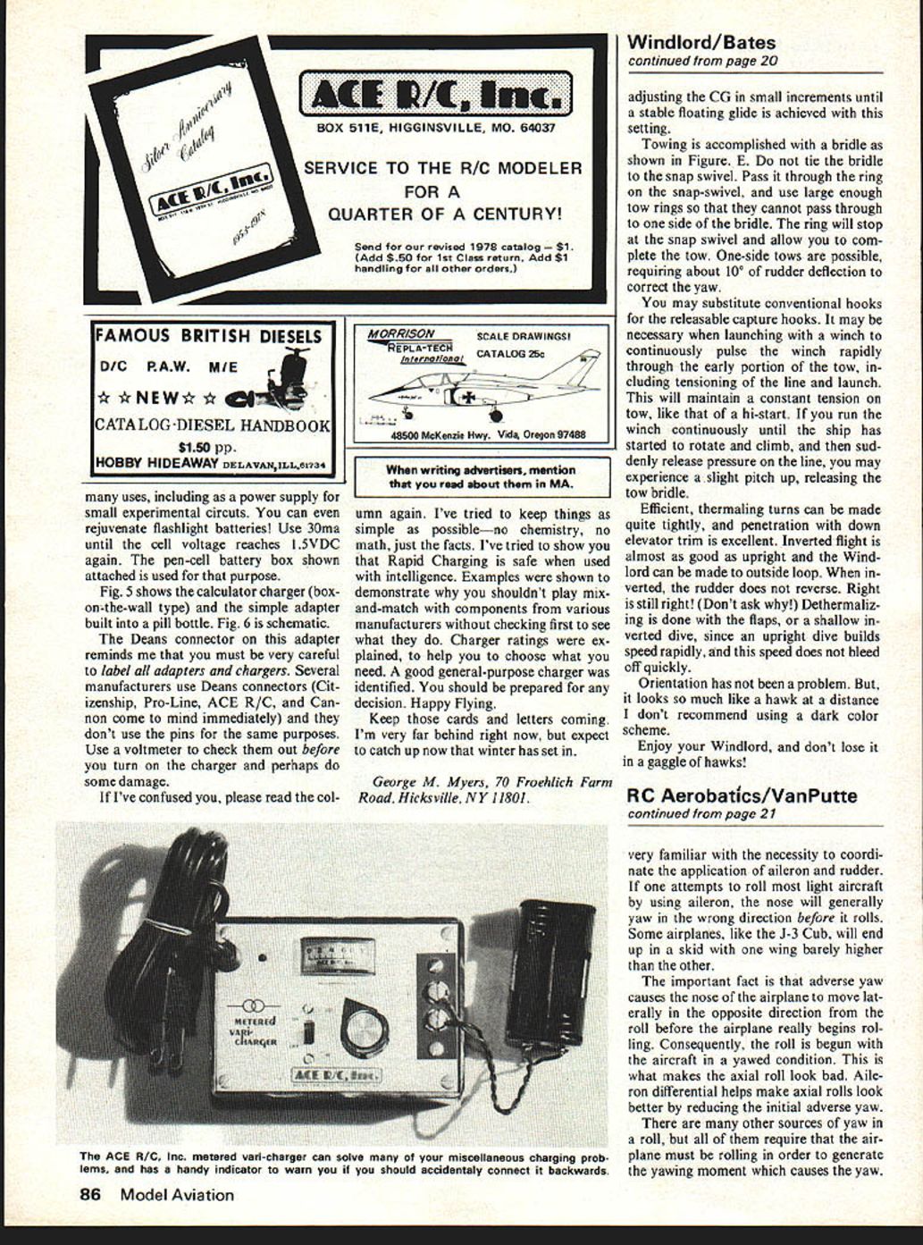
The Windlord has a wing span of 100 in., wing area of 1400 sq. in., and an aspect ratio of 7 to 1. I have built four Windlords weighing between 50-70 oz., with wing loadings of 5 to 7 oz./sq.ft. Control is by rudder-elevator, which responds in a conventional manner, along with provisions for optional lift and drag flaps on the underside of the wing. If the ship is kept under 70 oz., unballasted, performance is comparable to most Standard Class ships being flown in competition.
The NACA 23009-75 airfoil will not tow as well as a flat bottom section. This gives the Windlord a somewhat shorter dead-air time than the best Standard Class ships have. However, the rapid recovery and tight turning capabilities inherent in the design, produce a ship that will out thermal most conventional designs, and the high lift-to-drag ratio means that the Windlord can stay with a thermal farther down wind and still get back to land. The 1977 Contest record as of 8/22/77 is one first, two seconds, and three third places.
The Windlord project started about four years ago when I read about the Marski flying wings in Jim Marski's book. Using this information, I built a model along the lines of his Pioneer II. It flew well from a hand launch, but hi-start towing proved disastrous. As I found out later, this was through no flaw in Jim's designs, but through lack of thought on my part.
My interest in flying wings was kept alive through the next four years by the outstanding flight characteristics of small balsa and paper models thrown out of my fourth floor office window. This highly scientific research was executed by myself and my chief fellow experimental associate Keith Shaw, who usually said, "It looks funny, I wonder if it will fly."
I found in an old NACA wartime report, experiments on flying wing stability that indicated that I had been on the right track. A short time later, I found that my towing problem was due to using a conventional tow hook location on an unconventional design. The prototype Windlord followed shortly, and was a success right off the board.
The constant chord planform was based on my experiments (including swept planforms) and the NACA wartime reports on tailless models flown in the Langley free flight wind tunnel. These tests indicated that the non-swept center of pressure configuration offered the best longitudinal stability with the fewest drawbacks.
Swept-back wings have increased damping on the pitch and yaw axes. Since the NACA was trying to develop a stable bombing and gunnery platform, these characteristics were desirable. On models, however, the swept-back planform is highly unstable at very high angles of attack, where spanwise flow reduces tip lift, causing even higher angles of attack, resulting in violent whip stalls. Also, swept-back wings exhibit a dihedral effect at high angles of attack, which creates problems with roll axis control. Some of the Northrop wings had down-swept tips to function as rudders, and to counteract some of this dihedral effect. Swept-forward planforms (even tapered wings with straight leading edge), tend to stabilize in a nose high attitude and require wash-in at the tips to prevent this. However, the wash-in produced tip stall and spiral instability.
Now we go to the airfoil and wing shape. The airfoil is a 9% thick NACA 23009-75 (Jim Marski chose the 12%-thick 23012-75), which has sufficient reflex to produce a stable center of pressure (CP) without a large upsweep at the trailing edge (notorious for high drag). The airfoil has as good a coefficient of lift as most reflexed sections, and a higher stall angle than most. Reflexed sections have a lower coefficient of lift than conventional sections. This works out to about 70% as much lift as conventional airfoils at model Reynolds Numbers.
Keeping this in mind, a 1400-sq. in. wing with aspect ratio 7 to 1, is equal to a 1000-sq. in. wing with aspect ratio 10 to 1 (Olympic II, Wind Drifter, etc.). To pack 1400 sq. in. into a 100 in. wing span requires an aspect ratio of 7 to 1. If a tapered planform were chosen, the root chord would be rather large. With this in mind, a constant chord wing was chosen, also making construction, balancing, and stability calculations vastly easier.
Since the airfoils that are stable enough for use on a model flying wing have a lower lift coefficient, the wing loading must be in the 5.5 oz./sq. ft. region, to approximate an 8 oz./sq. ft. loading on a conventional design of 1000 sq. in. Therefore, the all up weight of 50-60 oz. is indicated.
The fin, rudder and elevator areas were arrived at by experimentation. The NACA reports are of little use here, since they are applicable only at higher Reynolds Numbers. The tow hooks are placed under the wing to preserve normal towing forces and moments, with the short "tail" moment.
From all of these considerations, and about eight wipe outs (which I won't discuss here), evolved the Windlord. So that one may not be tempted to innocently tinker with the design in critical areas, here is how it works.
In commenting on critical aerodynamic considerations, many of these statements are much simplified, but will provide the necessary information.
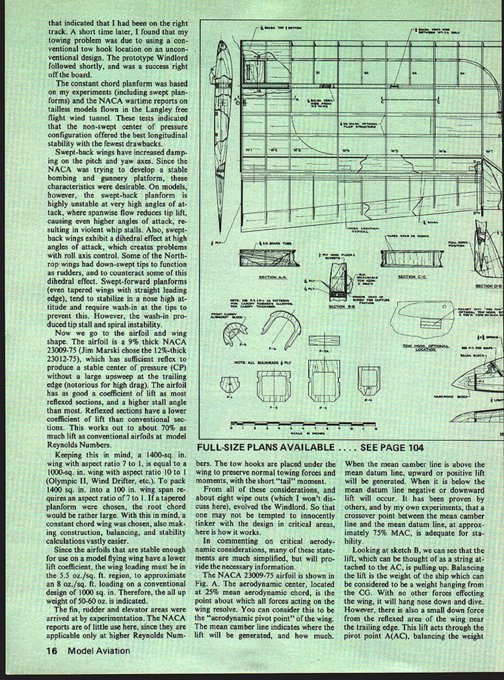
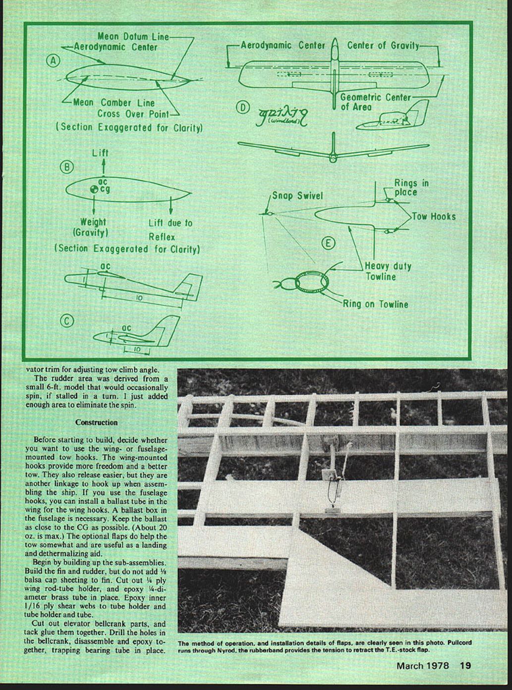
The NACA 23009-75 airfoil is shown in Fig. A. The aerodynamic center, located at 25% mean aerodynamic chord, is the point about which all forces acting on the wing resolve. You can consider this to be the "aerodynamic pivot point" of the wing. The mean camber line indicates where the lift will be generated, and how much.
When the mean camber line is above the mean datum line, upward or positive lift will be generated. When it is below the mean datum line negative or downward lift will occur. It has been proven by others, and by my own experiments, that a crossover point between the mean camber line and the mean datum line, at approximately 75% MAC, is adequate for stability.
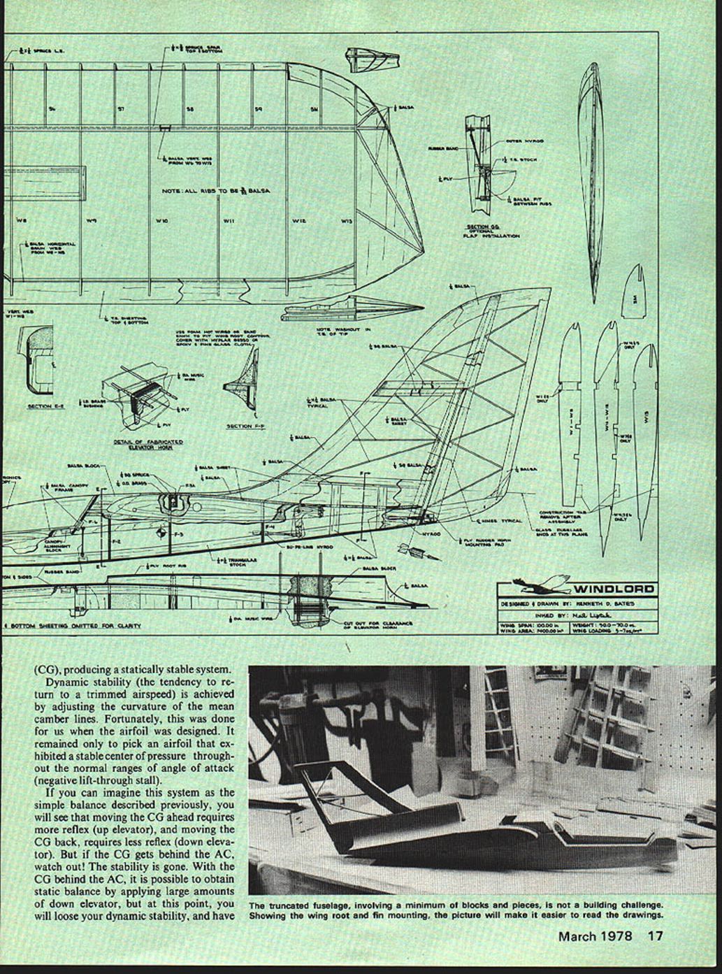
Looking at sketch B, we can see that the lift, which can be thought of as a string attached to the AC, is pulling up. Balancing the lift is the weight of the ship which can be considered to be a weight hanging from the CG. With no other forces effecting the wing, it will hang nose down and dive. However, there is also a small down force from the reflexed area of the wing near the trailing edge. This lift acts through the pivot point (AC), balancing the weight (CG), producing a statically stable system.
Dynamic stability (the tendency to return to a trimmed airspeed) is achieved by adjusting the curvature of the mean camber lines. Fortunately, this was done for us when the airfoil was designed. It remained only to pick an airfoil that exhibited a stable center of pressure throughout the normal ranges of angle of attack (negative lift-through stall).
If you can imagine this system as the simple balance described previously, you will see that moving the CG ahead requires more reflex (up elevator), and moving the CG back, requires less reflex (down elevator). But if the CG gets behind the AC, watch out! The stability is gone. With the CG behind the AC, it is possible to obtain static balance by applying large amounts of down elevator, but at this point, you will lose your dynamic stability, and have a moving AC, as there no longer is any reflex to the section. A moving AC will not allow the system to return to a balanced condition, because the fulcrum is moving with every deviation in trimmed airspeed. Thus, moving the "elevators" on the Windlord changes the amount of average reflex for the wing as a whole, without eliminating it entirely.
If you stall the ship, what then? The lift is gone and so is our stability. Wrong! Looking at sketch D, we see a top view of the Windlord with CG, CP and geometric center of area shown. Since the CG is ahead of the geometric center of area, a stall will eliminate the lift. The center of pressure is no longer the wing's pivot point, leaving us with an object that has more weight on one side than the other. If we drop (stall) this object, it will fall heavy side down (nose down), until lift is re-established, like a conventional design.
All of the stabilizing influences found on a conventional design are present on the Windlord. It's just so close coupled that there isn't any gap between the wing and the stab. The stab is there on the rear of the wing. The low moments of inertia inherent in this arrangement means that there isn't any need for a long tail moment. So much for the mystery of "tailless" designs.
Remember my tow problem? Keeping the previous explanation in mind, consider sketch C. The aerodynamic center on the wing of a conventional design is still the aerodynamic pivot point. On a design of normal fuselage depth and tail moment, the ratio of distances from the center of the horizontal stab to the AC, and the tow attachment point to the AC, is about 10 to 1. In order to preserve this moment ratio on the Windlord, the tow hooks have to be approximately 1 in. from the AC.
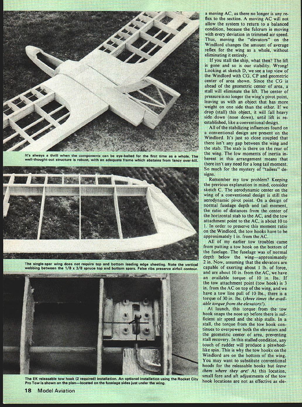
All of my earlier tow troubles came from putting a tow hook on the bottom of the fuselage. The fuselage was of normal depth below the wing—approximately 2 in. Now, assuming that the elevators are capable of exerting about 1 lb. of force, and are about 10 in. from the AC, we have an available torque of 10 in.-lbs. If the tow attachment point (tow hook) is 3 in. from the AC on top of the wing, and we have a tow line pull of 10 lbs., there is a torque of 30 in.-lbs. (three times the available torque from the elevators).
At launch, this torque from the tow hook snaps the nose up before there is sufficient airspeed and the ship stalls. In a stall, the torque from the tow hook continues to overpower both the elevators and the geometric center of area, preventing stall recovery. In this stalled condition, any touch of rudder will produce a pinwheel-like spin. This is why the tow hooks on the Windlord are on the bottom of the wing. You may want to substitute conventional hooks for the releasable hooks but leave them where they are! At this location, small fore and aft adjustments of the tow hook locations are not as effective as elevator adjustments.
Adjust the CG in small increments until a stable, floating glide is achieved.
Towing is accomplished by the bridle shown in Figure E. Tie the bridle to a snap-swivel. Pass the tow ring through the snap-swivel; use large enough tow rings—if they cannot pass through the side bridle ring they will stop the snap-swivel and not allow complete tow. One-side tows are possible, requiring about 10° rudder deflection to correct yaw. You may substitute conventional hooks for the releasable capture hooks; they may be necessary for winch launching. With a winch, continuously pulse the winch rapidly through the early portion of the tow, including tensioning the line. A launch will maintain constant tension on the tow line—like a hi-start; run the winch continuously. elevator trim for adjusting tow climb angle.
The rudder area was derived from a small 6-ft. model that would occasionally spin, if stalled in a turn. I just added enough area to eliminate the spin.
Construction
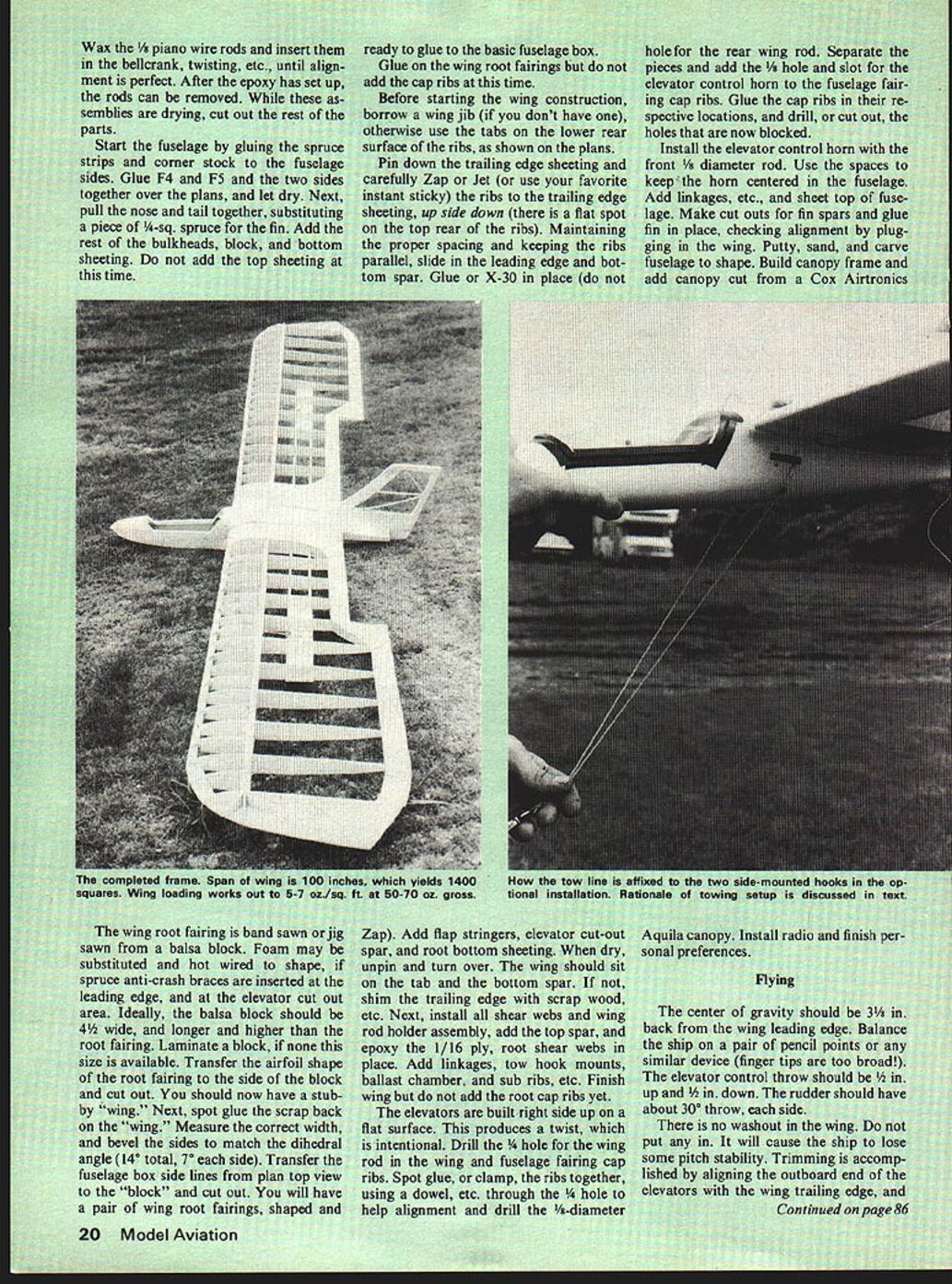
Before starting to build, decide whether you want to use the wing- or fuselage-mounted tow hooks. The wing-mounted hooks provide more freedom and a better tow. They also release easier, but they are another linkage to hook up when assembling the ship. If you use the fuselage hooks, you can install a ballast tube in the wing for the wing hooks. A ballast box in the fuselage is necessary. Keep the ballast as close to the CG as possible. (About 20 oz. is max.) The optional flaps do help the tow somewhat and are useful as a landing and dethermalizing aid.
Begin by building up the sub-assemblies. Build the fin and rudder, but do not add 1/8" balsa cap sheeting to the fin. Cut out 1/4" ply wing-rod tube holder, and epoxy 1/4" diameter brass tube in place. Epoxy inner 1/16" ply shear webs to tube holder and tube.
Cut out elevator bellcrank parts, and tack glue them together. Drill the holes in the bellcrank, disassemble and epoxy together, trapping the bearing tube in place.
Start the fuselage by pinning the sides and corner doublers over the plan and glue the corners. Glue former F4 and the nose piece in place and add sheeting as shown on the plan. When starting the wing, use the ribs with the grain side down; check rear spacing and glue ribs to the spar box. Add the rear shear web and glue the box assemblies together. Install control-horn ribs and glue horn locations. Block in the elevator control rod and center the horn on the elevator; install flanges and make cutouts for the control surfaces. Check alignment of the wing, fill and shape with putty where necessary.
Build the center section and complete the wing panels and tip details. The wing loading of the ship yields a light, slow landing speed and a gross weight suitable for safe towing and thermal work. Leading edge stock may be substituted with spruce for anti-crash protection. Add the flap structure at the root, install the bottom pin and turn-over tab on the trailing edge flap.
Next install the aileron assembly and root gussets; glue 1/16" ply root reinforcements and install servo linkages. Check tow-hook alignment and install the bridle hardware per the plan. Install references to flying: iterate CG and control throws by gravity glide and landing checks. Use two pairs of shim washers at the fin and root if needed—no washout will be required with the two-stage mounting setup. Wax the 1/8" piano wire rods and insert them in the bellcrank, twisting, etc., until alignment is perfect. After the epoxy has set up, the rods can be removed. While these assemblies are drying, cut out the rest of the parts.
Start the fuselage by gluing the spruce strips and corner stock to the fuselage sides. Glue F4 and F5 and the two sides together over the plans, and let dry. Next, pull the nose and tail together, substituting a piece of 1/4-sq. spruce for the fin. Add the rest of the bulkheads, block, and bottom sheeting. Do not add the top sheeting at this time.
When dry, the fuselage is ready to glue to the basic fuselage box.
Glue on the wing root fairings but do not add the cap ribs at this time.
Before starting the wing construction, borrow a wing jib (if you don't have one), otherwise use the tabs on the lower rear surface of the ribs, as shown on the plans. Pin down the trailing edge sheeting and carefully Zap or Jet (or use your favorite instant sticky) the ribs to the trailing edge sheeting, upside down (there is a flat spot on the top rear of the ribs). Maintaining the proper spacing and keeping the ribs parallel, slide in the leading edge and bottom spar. Glue or X-30 in place (do not drill the 1/8" hole for the rear wing rod).
Separate the pieces and add the 1/8" hole and slot for the elevator control horn to the fuselage fairing cap ribs. Glue the cap ribs in their respective locations, and drill, or cut out, the holes that are now blocked.
Install the elevator control horn with the front 1/8"-diameter rod. Use the spaces to keep the horn centered in the fuselage. Add linkages, etc., and sheet top of fuselage. Make cutouts for fin spars and glue fin in place, checking alignment by plugging in the wing. Putty, sand, and carve fuselage to shape. Build canopy frame and add canopy cut from a Cox Airtronics Aquila canopy. Install radio and finish per sonal preferences.
Flying
The center of gravity should be 3 1/4 in. back from the wing leading edge. Balance the ship on a pair of pencil points or any similar device (finger tips are too broad). The elevator control throw should be 1/2 in. up and 1/2 in. down. The rudder should have about 30° throw, each side.
There is no washout in the wing. Do not put any in. It will cause the ship to lose some pitch stability. Trimming is accomplished by aligning the outboard end of the elevators with the wing trailing edge, and adjusting the CG in small increments until a stable floating glide is achieved with this setting.
Towing is accomplished with a bridle as shown in Figure E. Do not tie the bridle to the snap swivel. Pass it through the ring on the snap-swivel, and use large enough tow rings so that they cannot pass through to one side of the bridle. The ring will stop at the snap swivel and allow you to complete the tow. One-side tows are possible, requiring about 10° of rudder deflection to correct the yaw.
You may substitute conventional hooks for the releasable capture hooks. It may be necessary when launching with a winch to continuously pulse the winch rapidly through the early portion of the tow, including tensioning of the line and launch. This will maintain a constant tension on tow, like that of a hi-start. If you run the winch continuously until the ship has started to rotate and climb, and then suddenly release pressure on the line, you may experience a slight pitch up, releasing the tow bridle.
Efficient, thermaling turns can be made quite tightly, and penetration with down elevator trim is excellent. Inverted flight is almost as good as upright and the Windlord can be made to outside loop. When inverted, the rudder does not reverse. Right is still right! (Don't ask why!) Dethermalizing is done with the flaps, or a shallow inverted dive, since an upright dive builds speed rapidly, and this speed does not bleed off quickly.
Orientation has not been a problem. But, it looks so much like a hawk at a distance I don't recommend using a dark color scheme.
Enjoy your Windlord, and don't lose it in a gaggle of hawks!
George M. Myers, 70 Froehlich Farm Road, Hicksville, NY 11801.
Transcribed from original scans by AI. Minor OCR errors may remain.

