
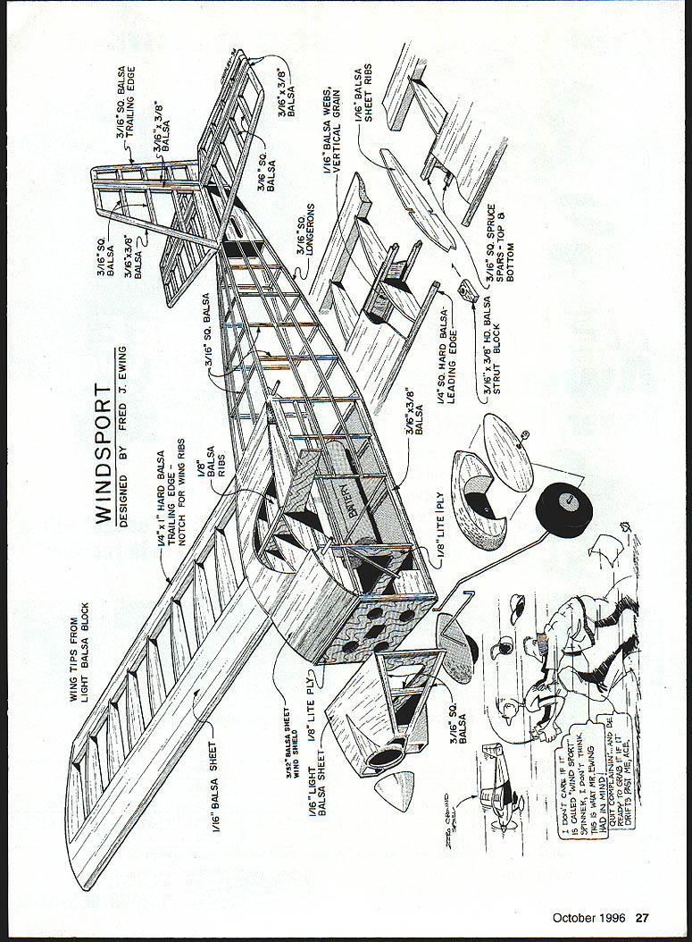
Windsport
Fred Ewing
Here's a "Reminder Scale" Electric for .05–.15 power
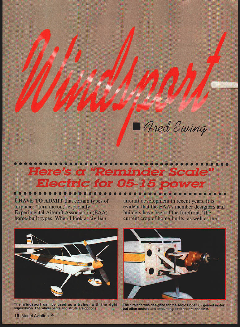
I have to admit that certain types of airplanes "turn me on," especially Experimental Aircraft Association (EAA) home-built types. When I look at civilian aircraft development in recent years, it is evident that the EAA's member designers and builders have been at the forefront. The current crop of home-builts, as well as earlier designs, are very appealing. Some examples of good-looking older designs are the Wittman Tailwind, the Nesmith Cougar, and the SD-1A Daphne.
One day, while trying to decide which electric model to build next, my eyes settled on a rubber-scale Tailwind model that was sitting on a nearby shelf. I started to sketch a rough outline similar to the model. As I progressed, I decided that it was not my intention to build a scale airplane, but rather one that would incorporate some of the distinguishing features of three or four different home-builts. The model would have simplified outlines to make it easy to build, and proportions suitable for a sport-type three-channel model.
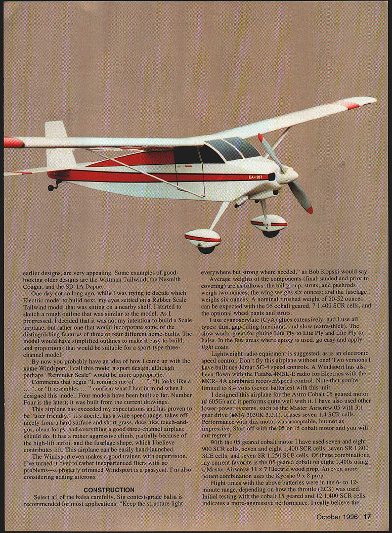
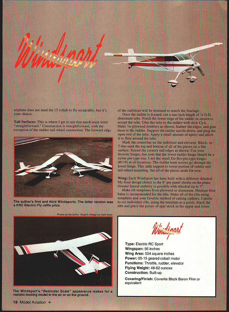
By now you probably have an idea of how I came up with the name Windsport. I call this model a sport design, although perhaps "Reminder Scale" would be more appropriate. Comments that begin "It reminds me of ...", "It looks like a ...", or "It resembles ..." confirm what I had in mind when I designed this model. Four have been built so far; Number Four is the latest and was built from the current drawings.
This airplane has exceeded my expectations and has proven to be user friendly. It's docile, has a wide speed range, takes off nicely from hard surfaces and short grass, does nice touch-and-goes and clean loops, and everything a good three-channel airplane should do. It has a rather aggressive climb, partially because of the high-lift airfoil and the fuselage shape, which I believe contributes lift. The Windsport can be easily hand-launched and even makes a good trainer, with supervision. A properly trimmed Windsport is a pussycat. I am also considering adding ailerons.
Construction
Materials, weights, and general advice
- Select all balsa carefully. Sig contest-grade balsa is recommended for most applications.
- "Keep the structure light everywhere but strong where needed."
- Average component weights (final-sanded, prior to covering):
- Tail group, struts, and pushrods: 2 oz
- Wing: 6 oz
- Fuselage: 6 oz
- Nominal finished weight: 50–52 oz expected with the .05 Cobalt geared motor, seven 1400 SCR cells, and optional wheel pants and struts.
- Use cyanoacrylate (CyA) glues extensively: thin, gap-filling (medium), and slow (extra-thick). Slow CyA works great for gluing Lite Ply to Lite Ply and Lite Ply to balsa. Where epoxy is used, apply light coats.
- Lightweight radio equipment and an electronic speed control (ESC) are suggested—do not fly without an ESC. Examples used: Jomar SC-4, Futaba 2NBL-E with MCR-40 (combined receiver/speed control). Note: the MCR-40 limits you to 8 volts (seven batteries).
- Recommended motors: Astro Cobalt .05 geared motor (Astro #605G) performs very well. Lower-power systems such as the Master Airscrew .05 with a 3:1 gear drive (M*A 3030K 3.0:1) work acceptably but are not as impressive. Start with the .05 or .15 Cobalt motor for best results.
- Battery combinations used successfully with the .05 geared Cobalt:
- Seven or eight 900 SCR cells
- Seven or eight 1400 SCR cells
- Seven SR 1800 SCE cells
- Seven SR 1250 SCE cells
- Current favorite: .05 geared Cobalt on eight 1400 SCE cells with a Master Airscrew 11 x 7 electric wood prop. Kyosho 9 x 8 prop gives even more potent performance.
- Flight times: 6–12 minutes depending on throttle use. The .15 geared Cobalt with twelve 1400 SCR cells gives a more aggressive performance.
Wing construction (center section and panels)
- Make rib templates from plywood or aluminum. Use medium-firm balsa for the ribs.
- Cut ribs using the template; stack and pin them with spar stock in notches, then block-sand lightly for uniformity. Check fit with mating parts.
- Start with the wing center section:
- Cover plans with waxed paper.
- Position and pin the lower spar; leave excess material on spars, trailing edges, and leading edges to be trimmed later.
- Make the trailing edge from firm 1/4 x 1 trailing-edge stock.
- Indicate centerline and mark rib locations. Cut notches in ribs (two pieces of hacksaw blade taped together work well).
- Pin the trailing edge and pin down the 1/16" lower sheeting. Note the opening forward in the lower sheet for the joiner. Apply thin CyA to sheet joints.
- Check fit and glue W1 ribs in place. Use a small square or triangle to vertically align ribs.
- Glue top spar and leading edge in place.
- Cut and check-fit top 1/16" sheeting from the trailing edge to the mid spar; make adjustments for fit but do not glue yet.
- Remove center section from plan, trim spars/trailing/leading edges flush with a sanding block or T-bar, and check outboard rib alignment.
- Make right and left wing panels:
- Rough-cut upper and lower spars oversize.
- Rough-cut trailing edge, mark and notch rib locations.
- Lay down and pin lower spar and trailing edge. Glue W3 and W4 ribs to spar and trailing edge.
- Place W2 root rib, set top spar and glue. Locate and glue leading edge.
- Accurately position and tilt W2 root rib to proper dihedral angle using a dihedral gauge; glue root rib to spars, trailing edge, and leading edge.
- Cut vertical-grain shear webs, check fit, and glue in place (omit shear webs in the area of the dihedral joiner).
- Make and glue strut blocks in place if using struts; consider installing 4-40 blind nuts in the blocks beforehand.
- Make and install gussets. Trim spars, trailing edge, and leading edge flush with root and tip ribs. Block-sand root and tip ribs.
- Joining panels to center section:
- Pin down the center section and check fit of panels. Do a dry run prior to final joining.
- Block up the wing panels the same amount to ensure proper root-fit. Mix slow-cure 30-minute epoxy and apply a light coat to mating surfaces. Join and clamp; wipe off excess epoxy with alcohol and allow to cure.
- Cut through W1 center-section ribs and W2 wing root ribs to create slots against the spar faces. Sand surfaces that will contact the dihedral joiner.
- Make dihedral joiner blank from 3/32" aircraft plywood (or as shown on plan). Fit, mark outline, saw to outline, and check fit with a dry run. Epoxy joiner in place with slow-curing epoxy; clamp and allow to cure. This method proves accurate for this joiner type.
- Balance shear webs, and fit 1/16" center-section top sheeting from the trailing edge to the mid spar. Omit forward top sheeting for access to the hold-down dowel assembly when fitting the wing to the fuselage.
- Fit top 1/16" leading-edge sheeting to both wings using soft, straight-grained balsa. Trim sheeting rear edge at the spar, butt the sheeting at the leading edge and apply masking tape at intervals so the sheet can hinge during gluing. Use slow CyA for rear-edge sheeting to the spar; thin CyA in small amounts between tape intervals will secure the leading edge to ribs. Trim excess sheeting at the tip rib and sand the entire wing.
- Make wingtips from light balsa and rough-cut contour. Check wing balance supported on the centerline. If one panel is heavier, use the lighter of two tip blocks on the heavy panel—both tip blocks are hollowed, but remove more wood from the heavier side's block. Hollow tips using wood-carving blades (e.g., X-Acto #135) rather than a Dremel. Glue tip blocks in place and finish shaping. Fill openings in the center-section lower sheeting with scrap balsa and sand the wing.
- Make the 1/4" plywood doubler for the wing's trailing edge, feather sides and glue to the center section. At this point you should have a complete wing except for the wing hold-down dowel assembly and the top-forward 1/16" center-section sheeting.
Tail surfaces
- Construction is straightforward except for the rudder-tail hinge connection.
- Frame the stabilizer and trim the forward edge to match the fuselage.
- Once the rudder is framed:
- Cut a 1" length of 1/8" O.D. aluminum tube. Notch the lower edge of the rudder to accept the tube and glue the tube to the rudder with slow CyA.
- Make 1/16" plywood doublers as shown, feather the edges, and glue them to the rudder.
- Support the rudder upside down, plug the open end of the tube, apply a small amount of epoxy and allow it to flow around the tube.
- Mark centerlines on stabilizer and elevator. Block- or T-bar-sand top and bottom of all pieces on a flat surface. Round corners and edges as shown.
- Use nylon pin-type lower rudder hinge (recommended Du-Bro small pin-type #119). Lower rudder horn screws go through the lower hinge to add support to the rudder and tail-wheel mounting.
- Set pieces aside until final fit-up.
Framing the fuselage
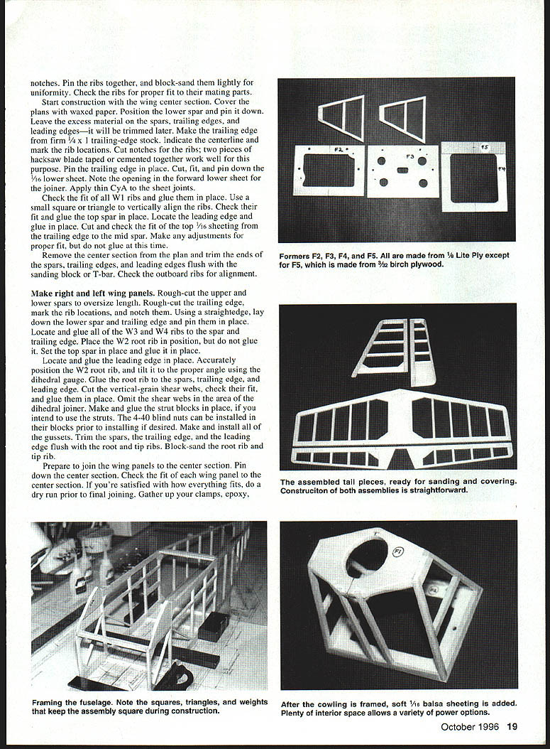
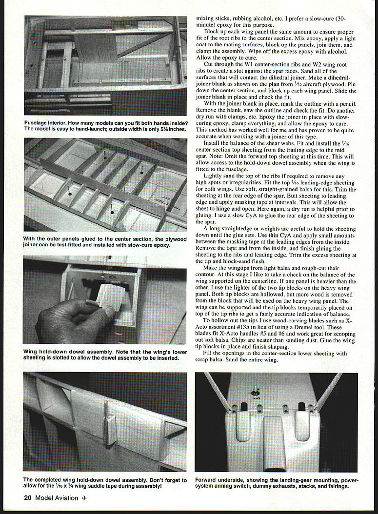
- The fuselage is a wide-body box-type construction—plenty of interior space allows easier installation of components and reduces the need for a hatch.
- Place waxed paper over the plans. Build two identical sides. Preferred method: build one side, remove it from the plan, leaving the other to pin pieces in place; then position the first side over the second to build the pair. Alternatively, tape joints on the first side and build the second over the first.
- Choose firm, matched pieces for longerons to assure correct symmetry when sides are drawn together at the tail post.
- Add gussets and sheeting at the tail after sides are removed from the plan. Block-sand both sides lightly to remove glue blobs or unevenness.
- Make nose former F1, cowling former F2, firewall F3, former F4, doubler F5, support F6, baffle F7 (optional), and the landing gear mount.
- All section views look aft.
- F5 and F6 are made from 3/32" x 3/8" plywood; cowling former F2 and firewall F3 are 1/8" Lite Ply.
- When using F2 as a template, drill small pilot holes and progressively step up drill sizes to final size. Open four screw holes in F2 to 5/32" diameter for 6-32 screws. Open 1/8" cooling holes in F3. Open center wiring-access hole and four blind nut holes and install four 6-32 blind nuts.
- Install two 1/8" alignment dowels in F2 (do not glue until cowling is made).
- The fuselage inside constant width is 4-1/8" from the front to section E-E. Prop up sides over the plan and begin framing by adding crosspieces, using 90° triangles or squares for squareness.
- Epoxy the gear mount to the longerons, making it flush at the front. Add former F4 and the fabricated frame at view E-E. Add 1/8" square doublers inside from F4 to view E-E.
- Bevel tail posts and glue them together, checking against the top view and fuselage centerline. Add the remaining crosspieces, tail wheel mount, floor pieces, and battery rails.
- Block-sand the front and trial-fit firewall F3. Glue F3 to the fuselage sides and install F1 as required.
- After cowling framing, add soft 1/16" balsa sheeting to keep assembly square during construction. Use slow-cure 30-minute epoxy as the preferred adhesive for these joints.
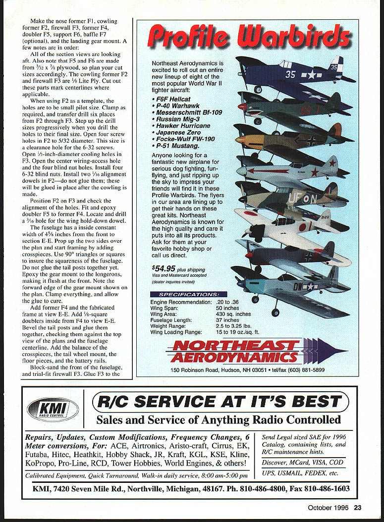
Landing gear and fittings
- Make left and right landing-gear legs from 1/8" music wire.
- Drill the gear mount and attach gear with 1/2" nylon landing-gear straps. Make and fit gear upright supports; remove gear and glue supports in place.
- Install support F6 using tapered filler block for proper angle alignment. Install 1/16" sheet balsa sides, capstrips, stabilizer saddle, stringers, filler between stringers, triangle stock, and servo rails.
- Make wheel pants optionally. For grass fields, consider 2-1/4" or 2-1/2" wheels without wheel pants. Wheel pants are better for hard surfaces or very short grass.
- Make balsa or plastic landing-gear fairings (I use .015" plastic). Attach with RC-56-type glue or contact cement but do not glue the upper 1/2" so the fairing can flex.
Cowling and nose
- The cowling is built from a frame covered with soft balsa sheet. Study plan top, side, and section views. Keep former F2 flat for a snug fit against firewall F3 and glue 1/16" alignment dowels in F2.
- Cowling attaches to the firewall with 6-32 x 3/8" socket head cap screws and washers. Screws and washers are inserted inside the cowling; the cowling is lowered onto the fuselage with dowels entering mating holes. A 1/4" x 6 ball wrench tightens the screws.
- The nose cowling can be made from balsa block or laminations. Glue to F1 and rough-shape now; final shaping is done with motor and spinner installed.
- Make the air scoop and optional exhausts. Install cowling and sand fuselage. Blend stringers with a sanding block or T-bar sander and round edges as shown in view E-E.
Motor and motor mount
- Install the motor and mount of your choice on firewall F3 and coordinate with cowling for proper fit.
- Clear inside F1 and the nose cowling as required for gearbox clearance. If needed, add a spacer block to the motor mount for fit.
- Final-shape the nose cowling and blend into a 1-1/4" diameter spinner.
Fitting the wing to the fuselage
- Contour the front of the fuselage so the wing contacts all surfaces; fill with scrap balsa as needed.
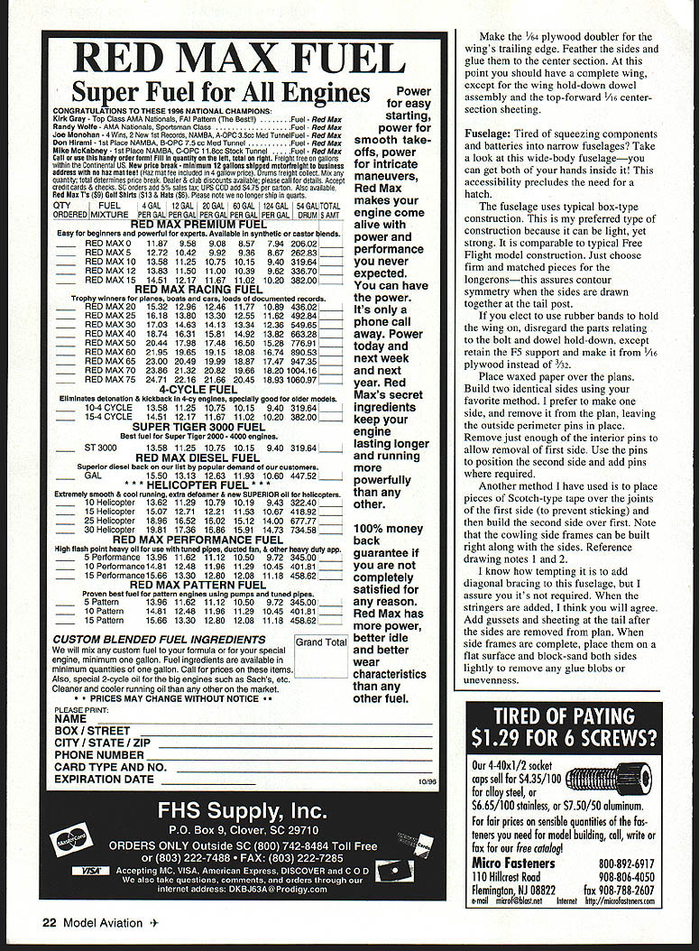
- Study the wing hold-down dowel section of the plans. Make the dowel and 1/8" x 3/8" side pieces and the openings in the center section. Glue the dowel to the side pieces; ensure the 1/16" x 3/4" wing-saddle tape is in place.
- With wing assembly clamped to rib W1, slide the wing in place and align the dowel to the 3/16" hole in F4 and F5. When satisfied, mark and remove the dowel assembly. Make and install 3/16" balsa filler and epoxy assembly to rib W1. Add forward-top 1/16" sheet to the wing center section and finish-sand.
- Install the wing bolt: align wing, drill a pilot hole through filler block and support F6, and progressively open hole to accommodate a 1/4" x 20 nylon bolt. Glue a Sig #218 threaded block to underside of support F6 with slow CyA or light epoxy.
- Install windshield after wing is bolted down: cut windshield from medium-soft 3/32" balsa, sand mounting surfaces for a close fit, install 1/4" triangle stock and two 1/16" square supports, glue windshield in place, radius corners, and chamfer rear inside edge as shown.
- If using optional struts, make them now. Drill holes, epoxy short lengths of white inner Nyrod into fuselage at proper angle (strut ends thread into these), and use 4-40 nylon screws to attach struts to wing.
Radio, servos, and final fit-up
- Preliminary fit-up of tail surfaces and radio installation prior to covering is recommended.
- Install servos, pushrods, radio components, speed control, switches, and power system. Check operation of radio, control surface movements, and power system.
- Typical control throws used: approximately 1/2" each way (adjust to preference).
- Remove components that will interfere with covering the model.
Miscellaneous items
- Make battery tray and fit to rails.
- Make optional wheel pants if desired.
- Make balsa or plastic gear fairings (.015" plastic recommended). Attach with RC-56-type glue or contact cement; leave the upper 1/2" unglued to allow flex.
Covering
- Any lightweight heat-shrink film may be used: Coverite Black Baron (used on two models for its light weight), MonoKote, UltraCote, Coverite 21st Century, etc.
- Usually cover tail surfaces off the airplane, leaving areas that will be glued free of film.
- Cowling: covered with four pieces; wheel pants with two pieces; struts with one piece.
- Use flat black acrylic enamel in cowl openings and on exhaust stacks; spray enamel on gear.
- Trim is Black Baron film and Coverite Presto. Side windows and windshield made from black Presto; gray, silver, or chrome are options. Door outlines are 1/8" striping tape. Air scoop and exhaust fairing covered and glued to cowling with RC-56-type glue.
- Don’t forget the triangle stock at the rear outlet; it serves as an air deflector, creating a low-pressure area and better airflow. Airflow through the airplane is excellent and has some venturi-like attributes.
Flying
- When detail covering is completed, check for warps. Slight washout in the wingtips is desirable.
- Assemble the airplane and reinstall all equipment. Balance the airplane where shown on plans; battery/tray can be moved to facilitate balance. Screw battery tray to rails with two 8-32 screws.
- Check all equipment operation. Perform preflight checks and range-check your radio with the motor running before first flights.
- Good luck and enjoy flying your own homebuilt. Happy Windsporting!
Specifications
- Type: Electric R/C Sport
- Wingspan: 56 in
- Wing area: 504 sq in
- Power: .05–.15 geared Cobalt motor
- Functions: Throttle, rudder, elevator
- Flying weight: 49–62 oz
- Construction: Built-up
- Covering/Finish: Coverite Black Baron film or equivalent
Fred Ewing 44 Blaine Ave., Apt A Hatfield, PA 19440
Transcribed from original scans by AI. Minor OCR errors may remain.

