
Wing and Tail Dihedral for Models
William F. McCombs
Purpose and background
The purpose of wing dihedral is to return the model to its trimmed attitude after a lateral upset (bank) caused by a disturbance such as gusty air or an improper launch. When the model is banked, one wingtip drops and the model begins to sideslip downward on that side. The sideslipping airflow generates slightly more lift on the lower wing and slightly less on the higher wing, which rolls the model back to its proper attitude (wings level or wings-banked).
More dihedral increases the restoring roll rate (good because less altitude is lost), but too much dihedral reduces the effective lifting area of the wing and hurts performance. Therefore a reasonable amount of dihedral is required and depends on model type.
Full‑scale airplanes usually have little or no wing dihedral because excessive dihedral degrades flying qualities such as roll rate. Free‑flight (FF) duration models commonly use generous dihedral; FF Scale models try to use scale dihedral, but using more than scale dihedral incurs scale penalties. When using small (scale) dihedral it is especially important that the vertical tail not be too large—too large a tail can cause spiral instability that cannot be cured by simple trim changes.
For detailed discussion and data on proper small vertical tail size see the referenced article "Vertical Tail Size for Models" (Ref. A) and the book (Ref. B).
Expressing dihedral as Equivalent V‑Dihedral (EVD)
Because there are many types of dihedral (V, outer‑panel, polyhedral, gull, inverted gull, etc.), it is convenient to express both required and actual dihedral as an equivalent V‑dihedral (EVD) — the single simple V angle that has equivalent rolling effect.
To choose a proper amount of wing dihedral one must determine:
- What the proper EVD is for the model type.
- How much EVD the model actually has.
Table 1 (below) summarizes EVDs used on successful models and shows typical ranges.
Table 1 — Typical Equivalent V‑Dihedral (EVD) by model type
- Nordic (towline) glider — 9–12°
- Hand‑launched glider — 12–17°
- Indoor rubber — 10–16°
- Outdoor rubber — 11–15°
- Gas‑power duration — 12–15°
- FF Scale, high wing* — 0–3°
- FF Scale, mid wing* — 0–5°
- FF Scale, biplane* — 1–4°
- FF Scale, low wing* — 3–8°
- RC, aileron‑equipped — see RC discussion
- RC, without ailerons — see RC discussion
*If following scale, use the scale dihedral when it is larger; also consider other effects discussed in the text.
A practical acceptance test for FF Scale minimum dihedral: launched forward at gliding speed from just above head height with the wings banked 40°, the model should roll out of the bank before it lands. The model must be trimmed for a straight, slow glide before the test.
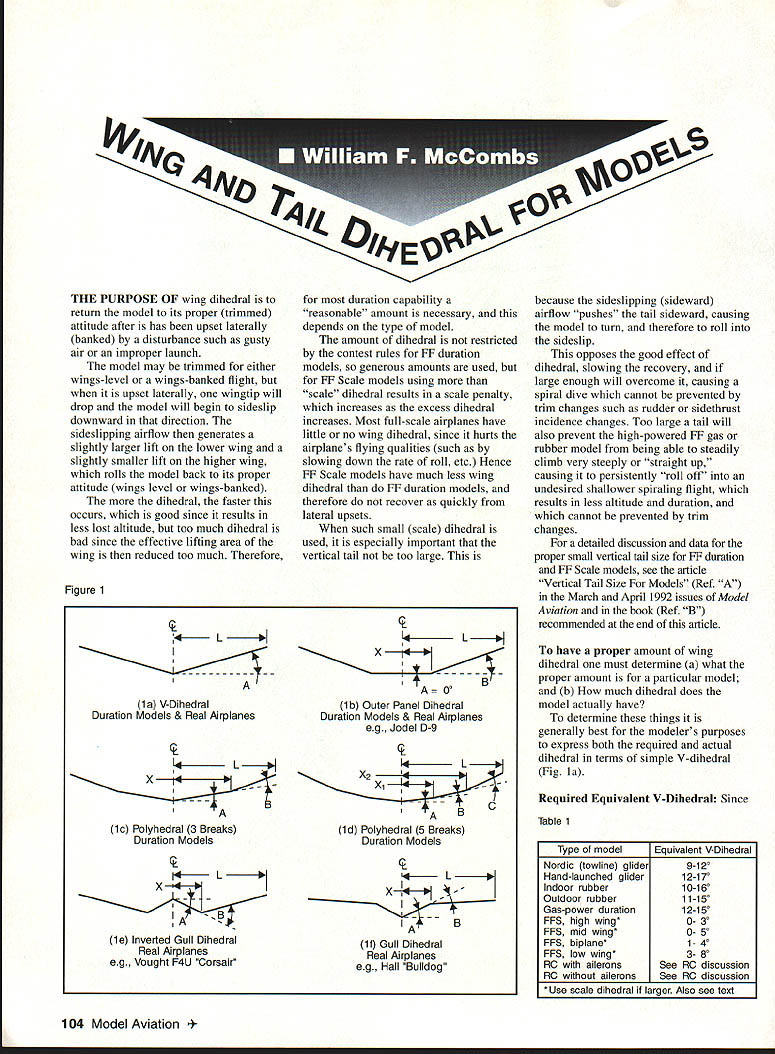
Types of wing dihedral (Figure 1)
Five main types are commonly used on models and full‑scale airplanes:
- (1a) V‑dihedral (single break) — simplest.
- (1b) Outer‑panel dihedral (two panels).
- (1c) Polyhedral (three breaks) — common on duration models.
- (1d) Polyhedral (five breaks) — seldom used; more work to build.
- (1e) Inverted gull dihedral (full–scale examples: Vought F4U Corsair).
- (1f) Gull dihedral (full–scale examples: Hall "Bulldog", Jodel D‑9).
Note: dihedral angles are measured relative to horizontal except that some angles in gull/inverted‑gull are measured downward and are negative in sign.
Calculating Equivalent V‑Dihedral (EVD)
For configurations with more than one dihedral break the EVD is calculated by summing the inner panel angle A plus a weighted contribution from the outer panel(s):
EVD = A + k·B
where:
- A and B are the known dihedral angles (degrees),
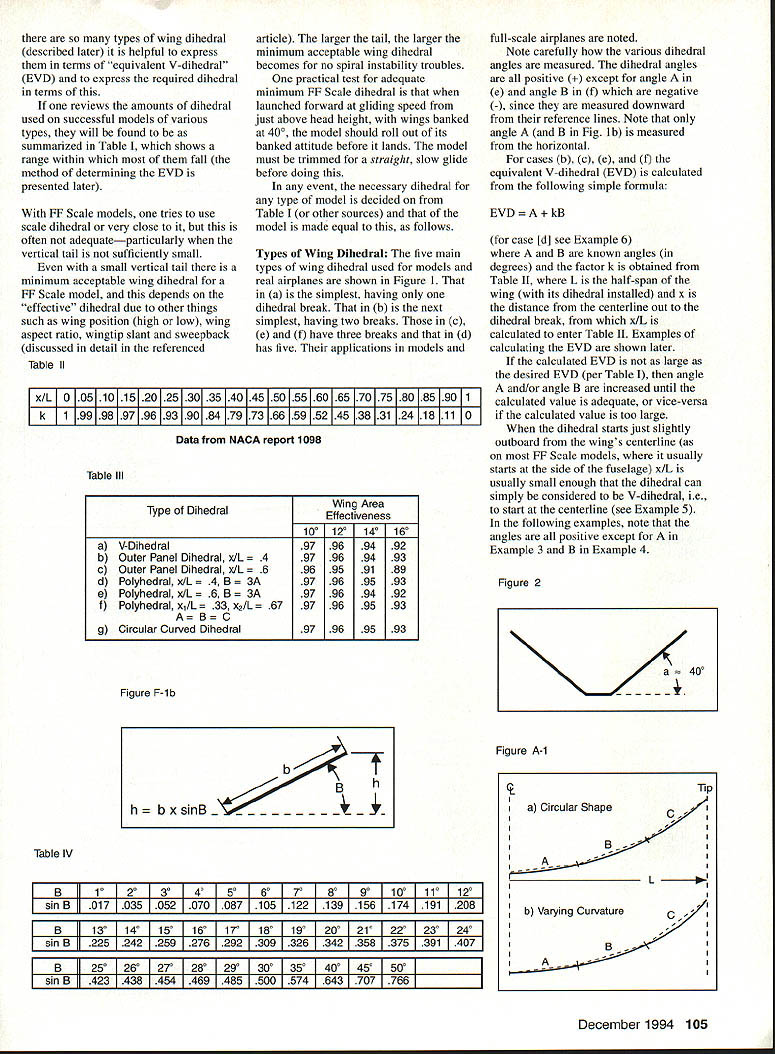
- k is a factor obtained from Table II based on the nondimensional break position x/L,
- L is the half‑span (with dihedral installed),
- x is the distance from centreline to the dihedral break (so x/L enters Table II).
For multiple outer breaks:
EVD = A + k1·B + k2·C + ...
(Table II is referenced for k values; see Appendix B for alternative k data.)
If the calculated EVD is not the desired value, increase or decrease A and/or B (or other break angles) until the EVD matches the target from Table 1. When the dihedral starts just slightly outboard of the centreline (typical on many FF Scale models where it starts at the fuselage side), x/L is small enough that the dihedral can be treated as a simple V starting at the centreline.
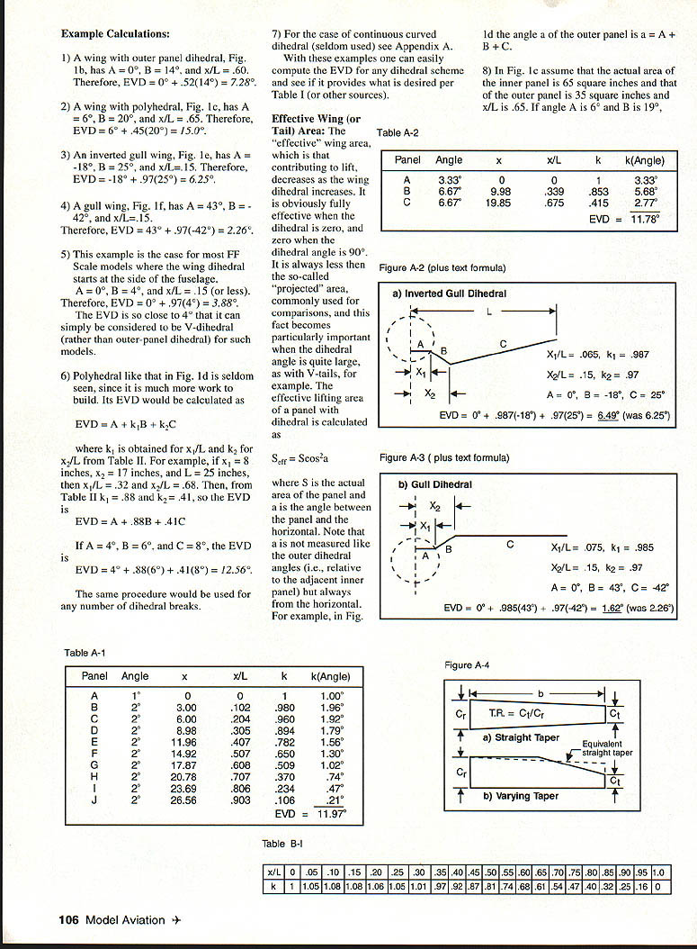
Examples of EVD calculations
- Outer‑panel dihedral (Fig. 1b): A = 0°, B = 14°, x/L = 0.60 → k = 0.52
EVD = 0° + 0.52×14° = 7.28°.
- Polyhedral (Fig. 1c): A = 6°, B = 20°, x/L = 0.65 → k = 0.45
EVD = 6° + 0.45×20° = 15.0°.
- Inverted gull (Fig. 1e): A = −18°, B = 25°, x/L = 0.15 → k = 0.97
EVD = −18° + 0.97×25° = 6.25°.
- Gull wing (Fig. 1f): A = 43°, B = −42°, x/L = 0.15 → k = 0.97
EVD = 43° + 0.97×(−42°) = 2.26°.
- Typical FF Scale (dihedral starts at side of fuselage): A = 0°, B = 4°, x/L = 0.15 → k = 0.97
EVD = 0° + 0.97×4° = 3.88°.
- Five‑break polyhedral (Fig. 1d): use EVD = A + k1·B + k2·C
Example: x1 = 8 in, x2 = 17 in, L = 25 in → x1/L = .32 (k1 = .88), x2/L = .68 (k2 = .41). If A = 4°, B = 6°, C = 8°: EVD = 4° + .88×6° + .41×8° = 12.56°.
- Continuous curved dihedral: see Appendix A (seldom used).
With these examples one can compute EVD for any break scheme and compare to the required EVD from Table 1.
Effective wing (or tail) area and dihedral
Increasing dihedral reduces the effective lifting area of the panel. A panel with area S at dihedral angle a (angle between panel and horizontal) contributes effective lift area:
S_eff = S cos^2 a
Note:
- a is measured from the horizontal (not relative to an adjacent panel).
- Projected area (S cos a) overestimates effectiveness; use cos^2 for lift contribution.
Example: Fig. 1c with inner panel area 65 in^2 and outer panel area 35 in^2, inner angle A = 6°, outer angle B = 19°, x/L = 0.65. If the effective total is 93 in^2, area effectiveness is 93/100 = 0.93 (93%). The projected method would give ~0.964 and thus be too optimistic.
Table III — Area effectiveness for same planform and EVD
Effectiveness shown for EVDs of 10°, 12°, 14°, 16° (rows are types; numbers are S_eff/S):
- a) V‑Dihedral
- 10°: .97 12°: .96 14°: .94 16°: .92
- b) Outer panel dihedral (x/L = .4)
- 10°: .97 12°: .96 14°: .94 16°: .93
- c) Outer panel dihedral (x/L = .6)
- 10°: .96 12°: .95 14°: .91 16°: .89
- d) Polyhedral (x/L = .4, B = 3A)
- 10°: .97 12°: .96 14°: .95 16°: .93
- e) Polyhedral (x/L = .6, B = 3A)
- 10°: .97 12°: .96 14°: .95 16°: .93
- f) Polyhedral (x/L = .33 and .67, A = B = C)
- 10°: .97 12°: .96 14°: .95 16°: .93
- g) Circular curved dihedral
- 10°: .97 12°: .96 14°: .95 16°: .93
Except for case (c) the differences in area effectiveness between dihedral types are minor. Cases (f) and (g) are more difficult to construct. Practical choices are (a), (b), (d) and (e). As EVD is made smaller, effectiveness increases and differences between types become smaller.
Setting dihedral angles
To set a panel dihedral B over panel half‑span b, raise one end a vertical distance h:
h = b × sin B
(Use sine values from trigonometry tables or the referenced Table IV.)
V‑tails
V‑tails replace conventional vertical+horizontal tails with two surfaces set in a V. Examples: Beechcraft Bonanza, Davis DA‑2A. They require mechanical coupling of control surfaces.
- Typical dihedral angle for each V‑tail surface is about 40°.
- For FF Scale models the effective vertical tail area must not be excessively large; too large a vertical (or V‑tail with large dihedral) will cause spiral instability and persistent roll‑off in steep climbs—trim changes cannot always cure this.
- The effective horizontal and vertical tail areas for a V‑tail (two panels of area S each, dihedral a) are:
- Effective horizontal tail area = 2S cos^2 a
- Effective vertical tail area = 2S sin^2 a
To meet a small required vertical tail area, the V‑tail dihedral angle may need to be reduced, and panel area adjusted by successive trials until both vertical and horizontal effectiveness are within acceptable ranges.
Example 9:
- V‑tail dihedral = 40°, panel area = 15 in^2 each.
- Effective vertical tail area = 2×15×sin^2(40°) = 2×15×0.413 = 12.4 in^2 (too large if required is 8 in^2).
- Reduce dihedral to 31°: effective vertical = 2×15×sin^2(31°) = 2×15×0.265 = 7.96 in^2 (OK).
- Check horizontal: S_ht = 2×15×cos^2(31°) = 30×0.735 = 22.05 in^2 (OK).
If horizontal area had been too small, increase panel area and reduce angle until the required vertical area is met.
Although V‑tails are infrequently used on FF models, they can work well for duration models; for these smaller (even negative) dihedral (cathedral) may be advantageous because it provides a positive rolling restoring effect when upset laterally.
Trim for glide turn: FF duration models trim turns by tilting the tail (as with conventional tails). FF Scale models use canting, elevons, or tabs for fine tuning.
RC models
The required dihedral depends on whether ailerons are fitted.
- RC with ailerons:
- Little or no wing dihedral is best for maneuverability. Too much total effective dihedral reduces roll rate, complicates coordination between rudder and ailerons, and makes the airplane overly sensitive in roll to small rudder deflections.
- Recommended effective dihedral: essentially 0° for midwings and biplanes; about 0°–2° for high and low wings. RC Scale models should match the prototype but can often improve maneuverability by using smaller values.
- RC without ailerons:
- Significant dihedral is needed for good rolling and turning using rudder‑induced roll.
- About 9° total effective dihedral is desirable. In terms of wing dihedral:
- High wings: ~5°–7°
- Midwings and biplanes: ~7°–8°
- Low wings: ~10°–11°
- Differences arise from wing position and fuselage geometry.
Note: inverted flight turns dihedral into cathedral and a high wing into a low wing, changing the effective dihedral of the airplane.
Effect of tapered planform on EVD
All EVD data above assume rectangular planforms. Tapered planforms yield slightly less EVD. For straight taper, define taper ratio TR = Ct/Cr (tip chord/root chord). Multiply the rectangular‑planform EVD by factor:
F = 0.8 + 0.2·(Ct/Cr)
F ranges between 1.0 (Ct = Cr, no taper) and 0.8 (Ct → 0).
For a wing of arbitrary taper or elliptical planform, determine an equivalent straight taper with the same area, span and root chord Cr. Compute tip chord as:
Ct = 2·(Area/span) − Cr
Then compute F and:
EVD_taper ≈ F × EVD_rectangular
Example:
- Elliptical wing: span = 36 in, root chord = 6 in, dihedral = 15°. Area = π·(36·6)/4 = 169.6 in^2.
- Ct = 2(169.6/36) − 6 = 3.42 in.
- F = 0.8 + 0.2(3.42/6) = 0.914.
- EVD_taper = 0.914×15° = 13.7°.
For a truly elliptical wing EVD_taper ≈ 0.914×EVD.
Appendices and data notes
- Appendix A discusses continuous curved dihedral and shows refined EVD calculations for gull and inverted‑gull cases where an inner panel (from centerline to fuselage side) of zero dihedral is included; this refines k factors slightly and changes EVD by small amounts (see examples in Appendix A).
- Appendix B notes that EVD calculations here are based on the k values in Table II. Alternative k values (e.g., from the 1990 NFFS Symposium paper by Hewitt Phillips) give larger k and thus larger EVDs for outer panels with x/L > 0.50. Table B‑1 contains those alternative k values.
- Table II and Table IV (sine/cosine values and k tables) are referenced for practical computation; consult the original article or appendices for tabulated values.
Summary and references
Using the guidance, tables, and examples provided, you can determine the required EVD for any FF model, calculate the model's actual EVD for the chosen dihedral configuration, and evaluate the effective wing and tail areas to avoid spiral instability or loss of duration.
Recommended references:
- Ref. A: "Vertical Tail Size for Models", Model Aviation, March–April 1992 (reprints available).
- Ref. B: Making Scale Model Airplanes Fly (1994 revision), AircraftData, Box 763576, Dallas, TX 75224; $14.95 postage paid.
(Technical review by Gil Morris; author acknowledges useful suggestions.)
Transcribed from original scans by AI. Minor OCR errors may remain.

