
Wing Master
Classic-profile 1/2A control-line appearance, present-day construction methods, and a larger-than-normal flapped wing go together to make this simple model ideal for sport flying or getting started in CL modeling. —James M. Petro
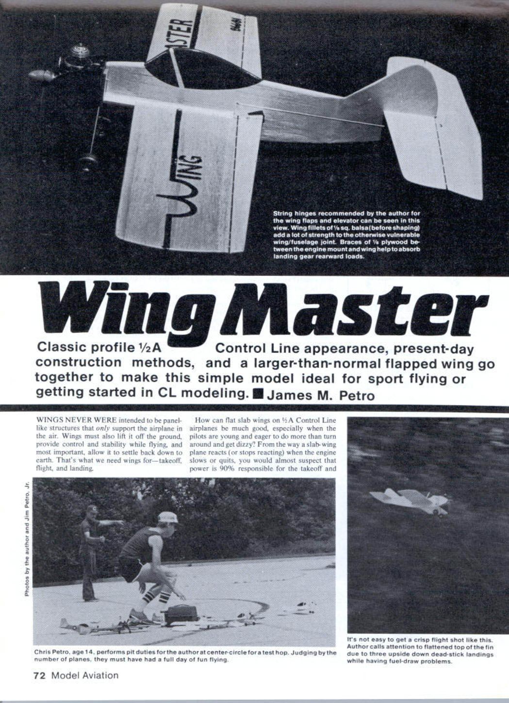
Wings were never intended to be panel-like structures that only support the airplane in the air. Wings must also lift it off the ground, provide control and stability while flying, and, most important, allow it to settle back to earth. That's what we need wings for—takeoff, flight, and landing.
How can flat slab wings on 1/2A control-line airplanes be much good, especially when the pilots are young and eager to do more than turn around and get dizzy? From the way a slab-wing plane reacts (or stops reacting) when the engine slows or quits, you would almost suspect that power is 90% responsible for the takeoff and flight, and the remaining 10% shows up when the plane plummets to the ground barely under control.
As boys became interested in CL, I decided I was going to make a kid-simple airplane controllable with a .049-powered stunter. I experimented with wing flaps on various Midwest and Sterling kits and modified wing flaps described in the June 1981 issue of Model Aviation. Wow — those planes became a lot better fliers. Later I wanted to put together a slab-wing CL with classic lines, wing flaps, and durability. I named it Wing Master; the subject of this article is the original design.
When the original design of this model was laid out, I noticed that 1/2A kits generally use smaller pieces of wood than what we can buy in the hobby shop. All the better for Wing Master, because it could grow to fit a full 4-in.-wide wing sheet that is just enough bigger to show that it is the wing doing the flying, not just the power. The fuselage was also enlarged and rounded to have a pleasant appearance and durability.
Four models were made, each with a different engine, and all flew better than expected. This model leaves the ground, maneuvers, and skims back to earth with smoothness and grace. Youngsters fly through a loop and come out of the circle with a big grin. Yes, there were some crashes on the asphalt, but all the breaks were in convenient places and very easy to repair with Hot Stuff glue.
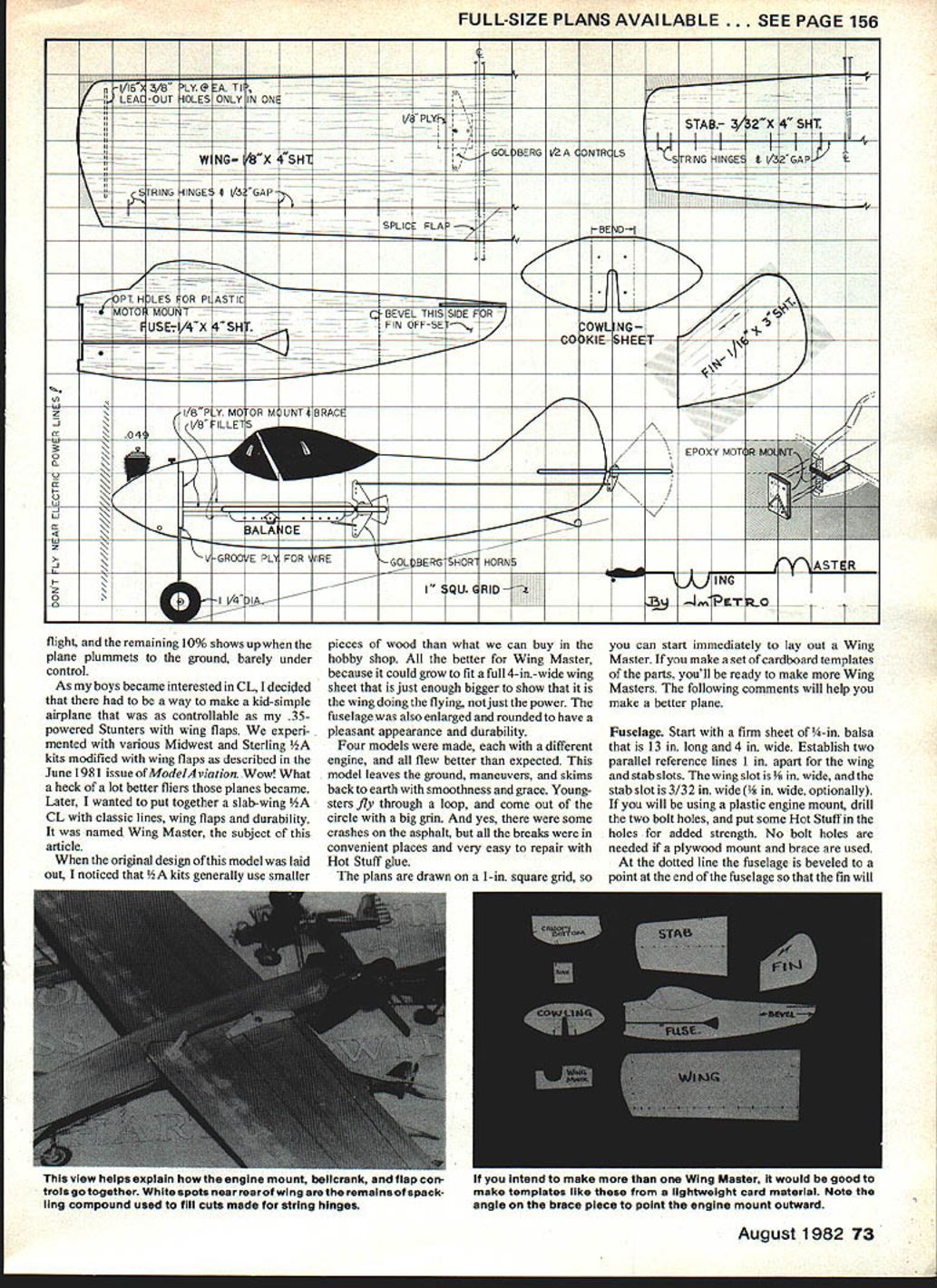
The plans are drawn on a 1-in. square grid, so you can start immediately to lay out a Wing Master. If you make a set of cardboard templates of the parts, you'll be ready to make more Wing Masters. The following comments will help you make a better plane.
Fuselage
Start with a firm sheet of 1/4-in. balsa that is 13 in. long and 4 in. wide. Establish two parallel reference lines 1 in. apart for the wing and stab slots. The wing slot is 1/8 in. wide, and the stab slot is 3/32 in. wide (1/16 in. wide optional). If you will be using a plastic engine mount, drill the two bolt holes and put some Hot Stuff or epoxy in the holes for added strength. No bolt holes are needed if a plywood mount and brace are used.
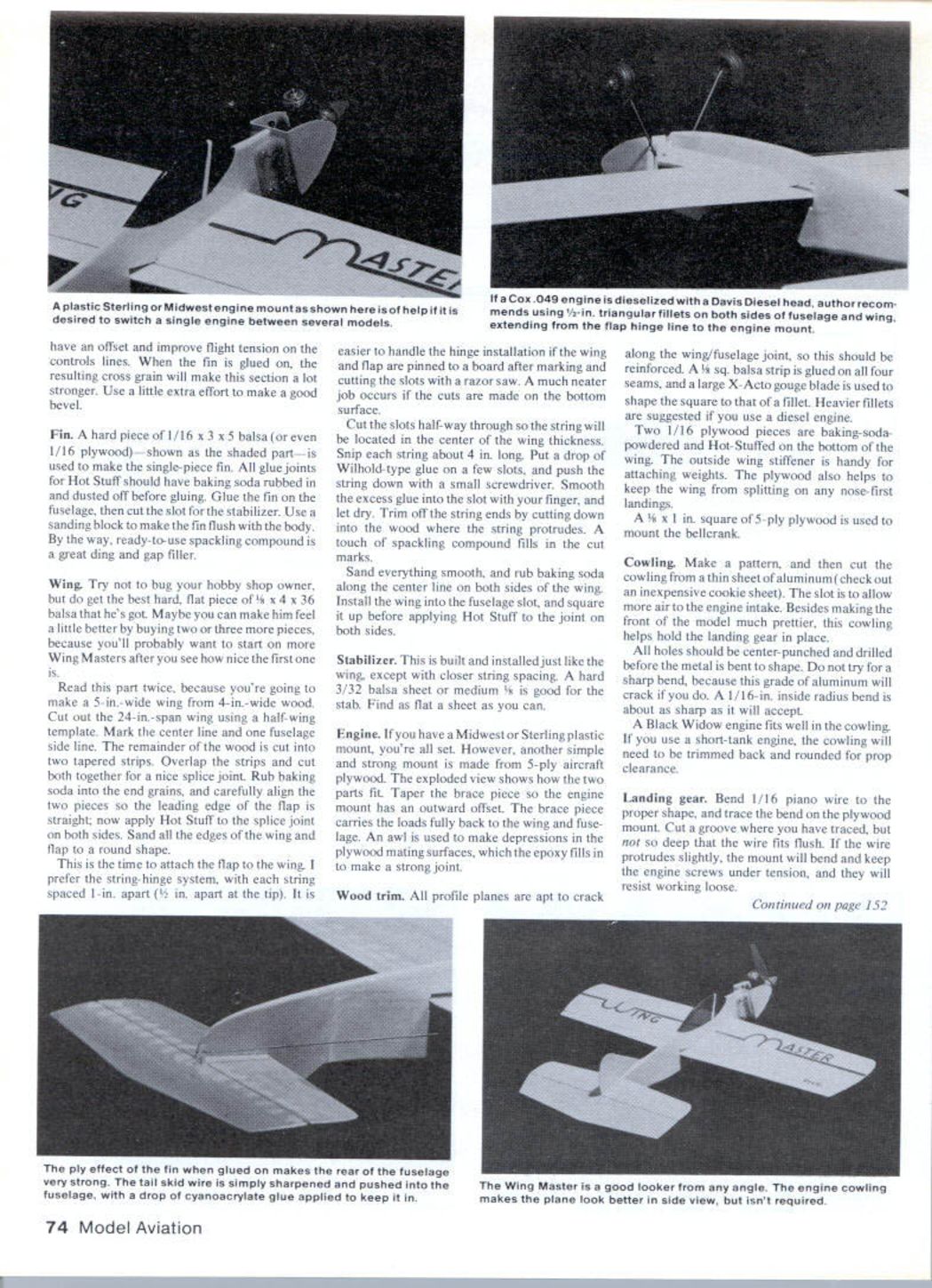
At the dotted line the fuselage is beveled to a point at the end so that the fin will be offset. Make templates of the parts from a lightweight card material if you intend to make more than one Wing Master. Note the angle on the brace piece to point the engine mount outward. Glue the fin to the fuselage; the resulting cross-grain will make the section a lot stronger. Use a little extra effort to make a good bevel.
Make the fin from hard 1/16-in. balsa sized about 3 x 5 in.; the 1/16-in. plywood shown on the plans is used to make a single-piece fin glue joint. Dust baking soda on the joints before applying Hot Stuff glue to help the joint set and strengthen the bond. Glue the fin to the fuselage and cut the slot for the stabilizer. Use a sanding block to make the fin flush with the body. Spackling compound is a great ding-gap filler.
Wing
Try your hobby-shop owner to get the best hard, flat piece of 1/8 x 4 x 36-in. balsa he has. Maybe you can make him feel a little better by buying two or three pieces because you'll probably want to start more Wing Masters after seeing a nice first. Read this part twice because you're going to make a 5-in.-wide wing from 4-in.-wide wood.
Cut out a 24-in. span wing using the half-wing template. Mark the center line and the fuselage side line. Cut the remainder of the wood into two tapered strips. Overlap the strips and cut both together for a nice splice joint. Rub baking soda on the end grains, carefully align the two pieces, and glue.
This is the time to attach the flap to the wing. I prefer the string-hinge system, with each string spaced 1 in. apart (1/2 in. apart at the tip). It is easier to handle the hinge installation if the wing and flap are pinned to a board after marking and cutting the slots with a razor saw. A much neater job occurs if the cuts are made on the bottom surface.
Cut the slots halfway through so the string will be located in the center of the wing thickness. Snip each string about 4 in. long. Put a drop of Wilhold-type glue on a few slots, and push the string down with a small screwdriver. Smooth the excess glue into the slot with your finger, and let dry. Trim off the string ends by cutting down into the wood where the string protrudes. A touch of spackling compound fills in the cut marks.
Sand everything smooth, and rub baking soda along the center line on both sides of the wing. Install the wing into the fuselage slot, and square it up before applying Hot Stuff to the joint on both sides.
Stabilizer
Build and install the stabilizer just like the wing, except with closer string spacing. A hard 3/32-in. balsa sheet or medium 1/8-in. balsa is good for the stab. Find as flat a sheet as you can.
Engine mounting
If you have a Midwest or Sterling plastic mount, you're all set. However, another simple and strong mount is made from 5-ply aircraft plywood. The exploded view on the plans shows how the two parts fit. Tape the brace piece so the engine mount has an outward offset. The brace piece carries the loads fully back to the wing and fuselage. An awl is used to make depressions in the plywood mating surfaces; epoxy fills the depressions to make a strong joint.
Wood trim and reinforcement
All profile planes are apt to crack along the wing/fuselage joint, so this should be reinforced. A 1/8-in. square balsa strip is glued on all four seams, and a large X-Acto gouge blade is used to shape the square into a fillet. Heavier fillets are suggested if you use a diesel engine.
Two 1/16-in. plywood pieces are dusted with baking soda and Hot‑Stuff glued on the bottom of the wing. The outside wing stiffener is handy for attaching weights. The plywood also helps to keep the wing from splitting on any nose-first landings.
A 4 x 1-in. piece of 5-ply plywood is used to mount the bellcrank.
Cowling
Make a pattern, and then cut the cowling from a thin sheet of aluminum (an inexpensive cookie sheet works well). The slot is to allow more air to the engine intake. Besides making the front of the model much prettier, this cowling helps hold the landing gear in place. All holes should be center-punched and drilled before the metal is bent to shape. Do not try for a sharp bend, because this grade of aluminum will crack if you do. A 1/16-in. inside-radius bend is about as sharp as it will accept.
A Black Widow engine fits well in the cowling. If you use a short-tank engine, the cowling will need to be trimmed back and rounded for prop clearance.
Landing gear
Bend 1/16-in. piano wire to the proper shape, and trace the bend on the plywood mount. Cut a groove where you have traced, but not so deep that the wire fits flush. If the wire protrudes slightly, the mount will bend and keep the engine screws under tension so they will resist working loose.
Select the wheels after the plane is finished so you can use their weight to get the correct balance point. The tail skid is made from extra pushrod wire and is glued with Hot Stuff.
Painting and finishing
Apply at least one coat of fuel-proof clear finish as a sealer and a minimum of two coats of fuel-proof color paint. I have had very good results with foam brushes (available at discount stores). The best technique is to brush slowly so the paint flows evenly. Templates for the canopy bottom outline and other decorations really help in making a neat model.
Try to avoid getting too much paint in the control-surface gap or on the string hinges. The hinges can be loosened, but movement of the elevator could be too limited if there is too much paint.
Always put on your AMA number. People will ask about it, and they are usually impressed with our organization.
Controls
I used parts manufactured by Carl Goldberg Models: BCH1-1/4 bellcrank and horn, and #CH-2 short control horns. Select the piano-wire size that best fits the control-linkage holes.
The lower horn on the wing flap needs two new holes to accept two screws from the upper horn. These two horns are mounted on the flap with their bases facing each other; nut plates are not used.
Very carefully make Z-bends on the pushrods so that the elevator and wing flap are each at level position when the bellcrank is parallel to the fuselage. The multiple holes in the lead-out plate will allow adjusting the line sweep-back for best flying with your setup.
Dacron flying line is used for the string hinges of the wing flap and elevator because it doesn't stretch, and the fibers glue well with the wood. The next improvement will be to find a transparent monofilament string that will also glue well; then the connection between the control surfaces could be nearly invisible.
Engine selection and flight notes
I like the Cox Black Widow engine for this model, though I suspect that a good amount of fuel is lost from the rear-end drain tube early in the flight. One possible modification is to cap the fill tube with a short length of fuel line sealed with a screw, and reroute the overflow tube with a short length of tubing brought sideways through a hole in the inner cowling. Would a capped fill tube and offset drain tube keep all the fuel in the tank? It's worth experimenting.
The standard Cox needle valve barely extends above the back edge of the cowling. You may want to consider some modification for better access.
Dacron flying line is recommended for the string hinges.
Conclusion and comments
During flight testing, two problems came up which I wish someone could solve. First, we need a fuel gauge that can be seen by the pilot. One Wing Master was inverted when it ran out of fuel. Second, we need a really simple engine-mount adapter that will permit switching engines between planes without having to remove screws. Besides saving time, it would save you from losing the screws.
For those who have wondered how long it takes to come up with a simple construction article like this 1/2A profile, the answer is six months. Think about that when someone complains that it takes a week to build the plane.
Finally, heed the warning about not flying near electric power lines. Remember that under some conditions power lines can pose a threat from the model being near them without actual contact. Never fly near power lines.
Transcribed from original scans by AI. Minor OCR errors may remain.

