

Winglets-Are They Worth It?
Whitcomb winglets are small, nearly vertical winglike surfaces mounted at the wing tips to reduce induced drag. Winglets were developed by Dr. Richard Whitcomb of the NASA Langley Research Center. Most published data has concentrated on improving the efficiency of subsonic jet transports; however, winglets have been installed on the new Learjet Longhorn business jet, two of Burt Rutan's efficient light planes, and the IAI Arava STOL transport. Therefore, winglets have proven effective at all subsonic Mach numbers at full-scale Reynolds numbers. The purpose of this article is to report on a preliminary investigation into the use of winglets on a 2-meter class sailplane.
Winglet Theory
The most complete single source of winglet information is contained in NASA TN D-8260: "A Design Approach and Selected Wind Tunnel Results at High Subsonic Speeds for Wing-Tip Mounted Winglets," by Richard T. Whitcomb. Bob Meuser summarized this report in his Free Flight column in the August 1977 issue of Model Aviation. I highly recommend that anyone seriously interested in winglets beg, buy, or borrow a copy of TN D-8260. This document is for sale by the National Technical Information Service, Springfield, VA 22161, and costs $3.75. For those interested in winglets but not $3.75 worth, I will try to summarize the portions applicable to model airplanes.
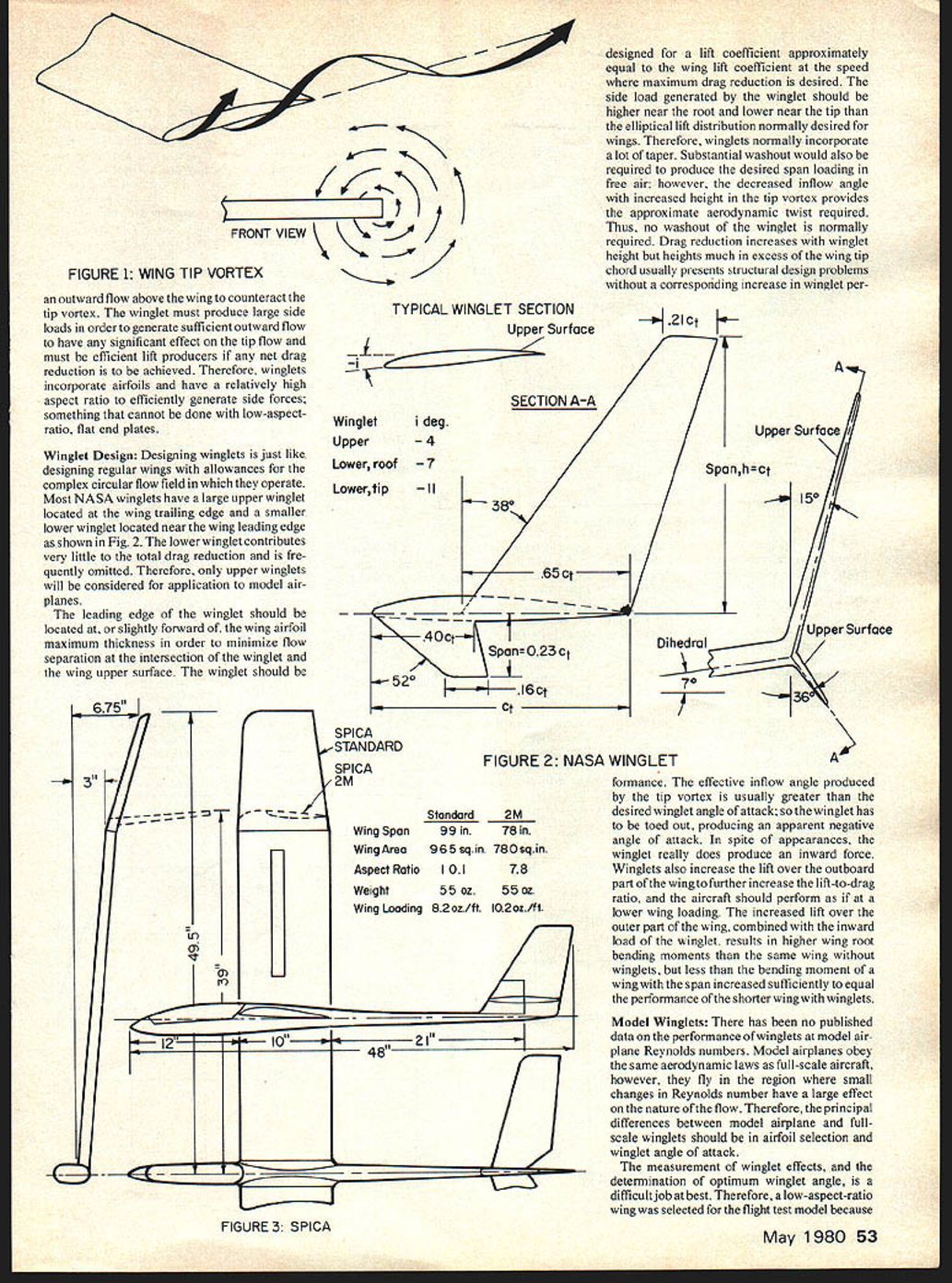
All lifting surfaces produce a higher pressure on the lower surface than on the upper surface. The high pressure below the wing tends to curl the air around the wing tip into the low pressure above the wing, forming a vortex that continues downstream. The tip vortex is responsible for induced drag, which is a large part of the total drag; any method of reducing its strength will reduce drag. It has long been known that tip plates will reduce induced drag; however, the increased friction and interference drag usually results in an increase in total drag.
Winglets reduce induced drag by generating outward flow above the wing to counteract the tip vortex. The winglet must produce large side loads to generate sufficient outward flow to affect tip flow significantly. It must be an efficient lift producer so a net drag reduction is achieved. Therefore, winglets incorporate airfoils and have relatively high aspect ratio to efficiently generate side forces — something that cannot be done with low-aspect-ratio flat end plates.
Winglet Design
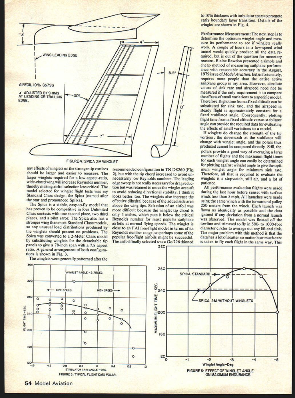
Designing winglets is much like designing regular wings except allowances must be made for the complex circular flow field in which they operate. Most NASA winglets have a large upper winglet located near the wing trailing edge and a smaller lower winglet located near the wing leading edge. The lower winglet contributes very little to total drag reduction and is frequently omitted. Therefore, upper winglets will be considered for application to model airplanes.
The leading edge of the winglet should be located slightly forward of the wing airfoil maximum thickness to minimize flow separation at the intersection of the winglet and the wing upper surface. The winglet should be designed with a lift coefficient approximately equal to the wing lift coefficient at the speed for which maximum drag reduction is desired. The side load generated by the winglet should be higher near the root and lower near the tip; an elliptical lift distribution is normally desired. Therefore, winglets normally incorporate a lot of taper. Substantial washout would also be required to produce the desired span loading in free air; however, the decreased inflow angle near the winglet tip caused by the vortex provides the approximate aerodynamic twist required. Thus no washout on the winglet is normally required.
Drag reduction increases with winglet height. Heights much in excess of the wing tip chord usually present structural design problems and the corresponding increase in winglet weight may offset performance gains. The effective inflow angle produced by the tip vortex is usually greater than the desired winglet angle of attack, so the winglet has to be toed out, producing an apparent negative angle of attack. In spite of appearances, the winglet really does produce an inward force. Winglets also increase lift over the outboard part of the wing. This increases the lift-to-drag ratio, and the aircraft should perform as if at a lower wing loading. The increased lift over the outer part of the wing, combined with the inward load of the winglet, results in higher wing-root bending moments than the same wing without winglets, but less than the bending moment of a wing with the span increased sufficiently to equal the performance of the shorter wing with winglets.
Model Winglets
There has been no published data on the performance of winglets at model airplane Reynolds numbers. Model airplanes obey the same aerodynamic laws as full-scale aircraft; however, they fly in a region where small changes in Reynolds number have a large effect on the nature of the flow. Therefore, the principal differences between model airplane and full-scale winglets should be in airfoil selection and winglet angle of attack.
The measurement of winglet effects, and the determination of optimum winglet angle, is a difficult job. Therefore, a low-aspect-ratio wing was selected for the flight test model because any effects of winglets on the stronger tip vortices should be larger and easier to measure. The larger winglets required for a low-aspect-ratio, wide-chord wing will increase Reynolds number, thereby making airfoil selection less critical.
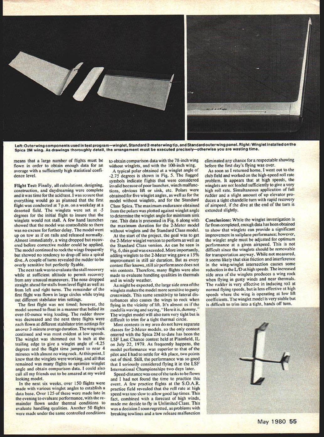
The model selected for winglet flight tests was my Standard Class design, the Spica (named after the star and pronounced Spi'ka). The Spica is a stable, easy-to-fly model that has proven competitive in four Unlimited Class contests with one second place, two third places, and one pilot error. The Spica also has a stronger wing than most Standard Class models, so any unusual load distributions produced by the winglets should present no problems. The Spica was converted to a 2-Meter Class model by substituting winglets for the detachable tip panels to give a 78-inch span with a 7.8 aspect ratio. A general arrangement of both configurations is shown in Fig. 3.
The winglets were generally patterned after the recommended configuration in TN D-8260, but with the tip chord increased to avoid unnecessarily low Reynolds numbers. The leading edge sweep is not really necessary for drag reduction but was retained to move the winglet area aft to avoid reducing directional stability. I think it looks better, too. The winglets also increase the effective dihedral because of the added side area above the wing tips.
Selection of an airfoil was more difficult because the winglet tip chord is only 4 inches, which puts it below the critical Reynolds number for most popular sailplane airfoils at normal flying speeds. The winglet is close to an FAI free-flight model in terms of its Reynolds number range, so perhaps some popular free-flight airfoils might be successful. The airfoil finally selected was a Go 796 thinned to 10% thickness with turbulator spars to promote early boundary layer transition. Details of the winglet are shown in Fig. 4.
Performance Measurement
The next step is to determine the optimum winglet angle and measure its performance. A couple of hours in a low-speed wind tunnel would quickly produce all required data, but that was out of the question for monetary reasons. Blaine Rawdon presented a simple and cheap method of measuring sailplane performance with reasonable accuracy in the August 1979 issue of Model Aviation, but it requires more people than the entire active sailplane group in my area.
However, absolute values of sink rate and airspeed need not be measured if the only requirement is to compare the effects of small variations to a specific model. Therefore, flight time from a fixed altitude can be substituted for sink rate, and the airspeed in steady flight is approximately constant for a fixed stabilator angle. Consequently, plotting flight time from a fixed altitude versus stabilator angle can provide the required data for evaluating the effects of small variations to a model.
If winglets do change the strength of the tip vortices, the downwash at the stabilator will change with winglet angle, and the polars thus produced cannot be compared directly. Still, the polars provide a good way of averaging a large number of flights, and the maximum flight times for each winglet angle can easily be determined for plotting against winglet angle to give the optimum winglet angle for minimum sink rate. Therefore, all that is required to evaluate the winglets is a stopwatch, still air, and a lot of patience.
All performance evaluation flights were made during the last hour before sunset with surface winds less than 5 mph. All launches were made using the same winch with the turnaround pulley 250 meters from the winch. Each launch was flown as identically as possible and the data were ignored if any deviation from a normal launch was observed. The model was floated off the towline and trimmed to fly in 500- to 1000-foot diameter circles to average out any lift and sink. The major problem with this method is that the data have a lot of scatter no matter how much care is taken to fly each flight in the same way. This is especially true of thermal activity which will often produce a change in sink rate during the last few minutes of the test period. However, plotting the maximum times for each angle tends to reduce the effects of thermal changes.
Flight Test
Finally, all calculations, designing, construction, and daydreaming were complete and it was time for the acid test. I was so sure that everything would go as planned that the first flight was conducted at 7 p.m. on a weekday at a deserted field. The winglets were set at 5 degrees for the initial flight to ensure that the winglets would not stall. A few hand launches showed that the model was controllable so there was no excuse for further delay.
The model went up on tow as if on rails and released normally. Almost immediately, a wing dropped but recovered before corrective rudder could be applied. The model continued to rock the wings frequently but showed no tendency to drop off into a spiral dive. A couple of turns revealed the rudder to be overly sensitive but perfectly flyable.
The next task was to evaluate stall recovery while at sufficient altitude to permit recovery from any unusual maneuvers. The nose dropped straight ahead for stalls from level flight as well as from left and right turns. The remainder of the first flight was flown in large circles while trying out different stabilator trim settings.
The first flight was not timed; however, the model seemed to float in a manner that belied its over-10-ounce wing loading. The rudder throw was decreased and the next three flights were each flown at different stabilator trim settings for an over 3-minute average duration. The wing rock continued and was most evident at low speeds. The winglet was shimmed out 1/8 inch at the trailing edge to give a winglet angle of -4.25 degrees and the flight time jumped to near 4 minutes with almost no wing rock. At this point I knew that the winglets were working and all that remained was many flights to optimize winglet angle and obtain comparison data.
In the next six weeks, over 150 flights were made with various winglet angles to establish a database. Over 125 of these were made late in the evening to evaluate performance, with the remainder flown under thermal conditions to evaluate handling qualities. Another 50 flights were made under the same controlled conditions to obtain comparison data with the 78-inch wing without winglets and with the 100-inch wing.
A typical polar obtained at a winglet angle of -2.75 degrees is shown in Fig. 5. The flagged symbols indicate flights that were considered invalid because of poor launches, equipment malfunction, obvious lift or sink, etc. Polars were obtained for five winglet angles, as well as for the model without winglets and for the Standard Class Spica. The maximum endurance obtained from the polars was plotted against winglet angle to determine the winglet angle for minimum sink rate. This data is presented in Fig. 6 along with the maximum duration for the 2-Meter model without winglets and the Standard Class model.
At the start of the project the goal was to get the 2-Meter winglet version to perform as well as the Standard Class version. As can be seen in Fig. 6, this goal was exceeded. More importantly, adding winglets to the 2-Meter wing gave a 15% improvement in still-air duration. But as every contest flier knows, still-air performance does not win contests. Therefore, many flights were also made to evaluate handling qualities in thermals and in windy weather.
As might be expected, the large side area of the winglets makes the model more sensitive to gusty crosswinds. This same sensitivity to lateral disturbances also causes the wings to rock when flying in the vicinity of lift. It's almost as if the model is swaying and saying, "Here it is, dummy." The winglet model will also turn very tight but is difficult to trim for a tight thermal circle.
Most contests in my area do not have separate classes for 2-Meter models, so the only contest entered with the Spica 2M to date was the LSF Last Chance contest held at Plainfield, IL on July 22, 1979. As frequently happens, the contest performance was superior to that of the pilot and I had to settle for 4th place, two points out of third. Still, the performance was so good that I seriously considered flying it in the LSF International Championships two days later.
Speed-distance was one of the tasks to be flown and I had not found the time to practice this event. A few practice flights at the S.O.A.R. practice field revealed that the roll rate at high speed was too slow to allow good lap times. This fact, combined with a forecast of high winds, made me decide to fly in Unlimited Class. This was a decision I soon regretted, as problems with breaking towlines and a tow release malfunction eliminated any chance for a respectable showing before the first day's flying was over.
As soon as I returned home, I went out to the club field and worked on the high-speed roll rate problem. It appears that at high speeds the winglets are not loaded sufficiently to give a very high roll rate. Simultaneous application of full rudder and a slight amount of up elevator produces a tight, handleable turn with rapid recovery of airspeed, if the dive at the end of the turn is extended slightly.
Conclusions
While the winglet investigation is far from completed, enough data has been obtained to show that winglets can provide a significant improvement in sailplane performance; however, the winglet angle must be adjusted for best performance at a given airspeed. This is not difficult since the winglets should be removable for transportation anyway.
While not measured, it seems likely that skin friction and interference at the wing–winglet intersection cause some reduction in L/D at high speeds. The increased side area of the winglets produces a wing rock when flying in gusty winds and near thermals. The rudder is very effective in inducing roll at normal flying speeds, but is less effective at high speeds where the wing is operating at low lift coefficients. The winglet model is very stable but is difficult to trim into a tight, hands-off turn.
Transcribed from original scans by AI. Minor OCR errors may remain.

