
Winter Hawk
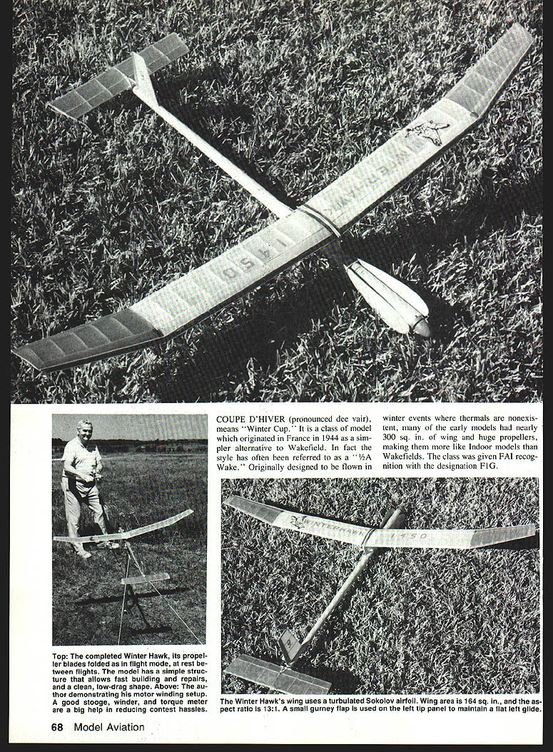
COUPE D'HIVER (pronounced "dee vair") means "Winter Cup." It is a class of model that originated in France in 1944 as a simpler alternative to Wakefield (FAI designation F1G). Early Coupe d'Hiver models featured large wings and props to fly in winter conditions with no thermals; over time the class evolved toward faster, Wakefield-like performance to handle summer thermals and moderate winds. The Winter Hawk is a simple, quick-building, clean-lined Coupe designed to be competitive in calm and moderate conditions. It was awarded Ft. Worth Planesmen's Best New Design (1983) and has won numerous contests, including Open Coupe at the 1987 Nats in Lincoln, NE.
Basic specifications
- Wing area: 164 sq. in.
- Aspect ratio: 13:1
- Airfoil: turbulated Sokolov airfoil
- Left tip: small gurney flap to maintain a flat left glide (helps keep turns out of thermals)
- Propeller: pre-carved blades (Blue Ridge Models recommended) with a torque-sensitive prop stop to eliminate rubber bunching and improve transition, climb, and glide
- Cross-section: meets the 31 sq. in. requirement
- Design goals: clean low-drag shape, fast building, easy repairs
Fuselage
- Materials and sizing
- Use a single piece of light, even-grained 1/16" sheet balsa, 3" x 36".
- Taper the last 24" slightly aft to a width of about 1 7/8". Remove the triangular scrap from each side as shown on the plan (approximately 9/16" x 24" triangle from each side in the tapered section).
- Forming the body tube
- Seal the inside with two coats of thick nitrate dope, allowing about two hours between coats.
- After the second coat is dry, immerse the sheet in hot water for about 10 minutes so it begins to curl.
- With the sheet wet, slide it onto a round mandrel approximately 1" diameter (an old pool cue works well).
- Wrap the tube with Ace bandage or other similarly stretchy, porous cloth. Allow a day or more for thorough drying.
- When dry, remove from the mandrel and close the seam with CyA (cyanoacrylate). Sand smooth, apply a coat of sanding sealer, sand lightly, then cover the tube with a layer of Japanese tissue adhered with thinned dope to smooth wrinkles.
- Note: the tissue will need to be removed later where components attach (pylon, rear rubber support band, tail parts). Excise those areas by lightly cutting and brushing thinner.
- Wing-mount pylon
- Build from three 2-1/2" x 3" pieces of lightweight 1/16" balsa edge-glued into a 9" strip with the grain vertical.
- Apply dope to the center inside to help form around the two ribs.
- Transfer rib contours from the plan by xeroxing and ironing the shapes onto the balsa as templates. Assemble the pylon ribs per the plan.
- Cut the bottom of the pylon roughly to shape, then finish by rubbing fore-and-aft on 180-grit sandpaper wrapped around the body tube. Seal and cover the pylon with Japanese tissue, then attach it to the body tube at the location shown on the plans, with the tube seam on the bottom.
- Glue the two bulkheads to form the short winglike structure and center the long 9" strip on the nose with about 3/8" of strip below the rib (this side attaches to the fuselage). Make the plywood wing mount and snuffer tube but do not mount them yet.
- Nose reinforcement and finishing
- Reinforce the nose with a 1" wide band of silk, nylon, or graphite cloth liberally coated with five-minute epoxy. After epoxy cures, cut the nose to the correct down- and side-thrust angles.
- Cut three small notches in the front end as shown on the drawing; recoat the front edge with epoxy. Add the small balsa bullet shape to the rear end.
Fin, rudder, stabilizer, and DT system
- Construction and alignment
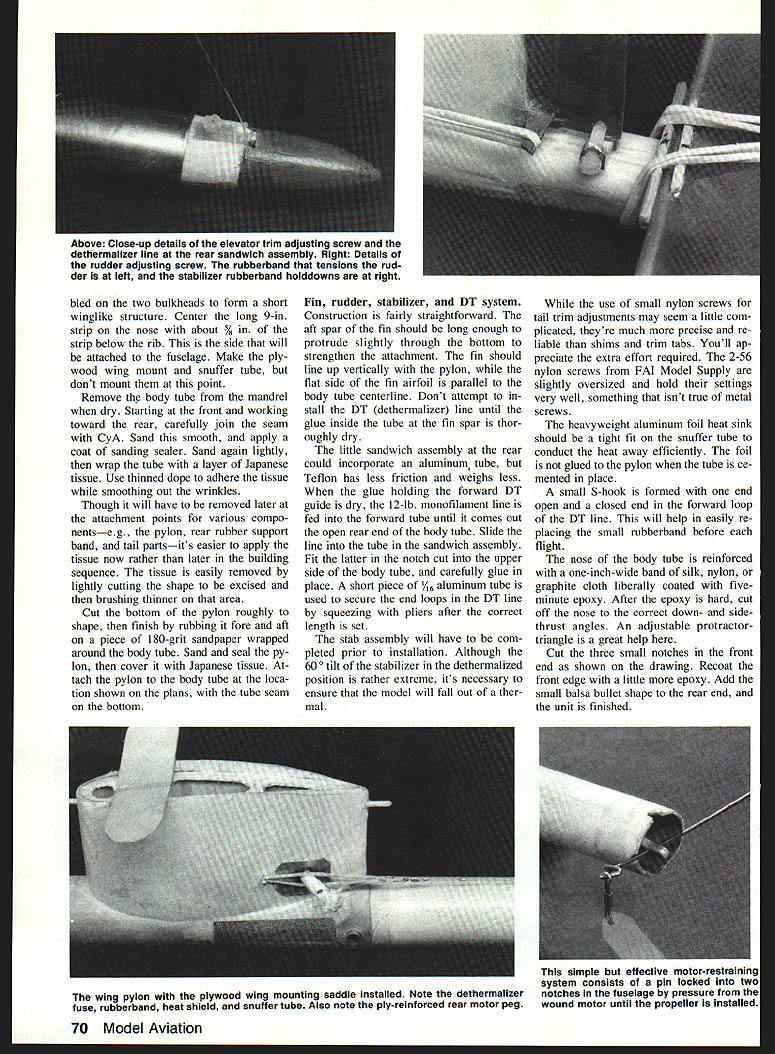
- Build the fin so the aft spar protrudes slightly through the bottom to strengthen the attachment. The fin must align vertically with the pylon; the flat side of the fin airfoil should be parallel to the body tube centerline.
- Fit the stabilizer prior to installation; the design uses a 60° tilt of the stabilizer in the dethermalized position to ensure the model will fall out of a thermal. Ensure the stabilizer saddle is true fore and aft; shim as necessary to obtain correct incidence.
- DT (dethermalizer) line and guides
- Use a Teflon tube for guides (less friction, lighter than aluminum). Feed the 12-lb monofilament DT line through the forward tube until it emerges the rear of the body tube, then slide it into the rear sandwich assembly and fit that into the notch on the upper side of the body tube. Glue carefully.
- Secure end loops on the DT line with a short piece of 1/16" aluminum tube (squeeze with pliers).
- Do not attempt to install the DT line until glue inside the tube at the fin spar is thoroughly dry.
- Clevises, hooks, and hardware
- Use a small S-hook with one end open and the other closed in the forward DT loop to allow easy replacement of the small rubber band before each flight.
- Small nylon screws (2-56 nylon screws from FAI Model Supply) for tail trim adjustments are recommended for precision and reliability; they hold settings better than metal screws.
- The heat sink (heavyweight aluminum foil) should fit tightly on the snuffer tube to conduct heat away efficiently; do not glue the foil to the pylon when cementing the tube.
Wing
- Ribs and templates
- Make a template for the 22 identical ribs by tracing the xeroxed largest rib onto aluminum or 1/32" plywood. Orient the template slightly nose-down on the wood grain so the grain is parallel with the narrow rear edge.
- Use the template to cut out ribs. Stack the 22 ribs on a short piece of 1/16" sq. stock in the upper spar groove and sand out imperfections. Use a sanding block to even the front and back edges.
- Building center panels
- Cover plans with wax paper. Tack-glue small pieces of 3/32" balsa to the forward edge of the trailing edge bottom surface to hold the proper airfoil angle.
- Pin a length of 1/16" sq. stock to the plans 1/4" forward of the trailing edge so rib back ends rest on it (not glued).
- Use two ribs to locate the leading edge (location may vary depending on rib sanding).
- Make a dime-sized puddle of CyA off to the side. Dip the leading and trailing ends of each rib in the puddle and locate the rib between the leading and trailing edges. Ensure each rib is straight as installed.
- Tilt the center ribs 7°. Add the lower 1/32" spar and the gussets (small 30 x 60° triangles, grain parallel to the hypotenuse). Remove pins and lift the panel from the wax paper, then add the lower 1/4" spar.
- Install 1/8" balsa sheeting on the leading edge while the panel is free of the plan. Repin with the outermost end down in line with the tip panel and the center rib raised 3-1/2" from the surface. Glue leading and trailing edges, spars, and 1/32" balsa sheeting directly to the center panel, then build the outboard tip panels.
- Joining and reinforcing
- Ensure vertical-grained spar webs at the joint fit tightly against the transition rib. Sand each wing half to correct leading and trailing edge shapes before joining.
- With one center panel pinned, trial-fit the other panel supporting it as shown on the plan, sand to match rib surfaces, then glue panels together. Add a 1/8" wide strip of silk or graphite reinforcing cloth over the top of the center joint.
- Add spar webs. If available, CyA a few 6" long strands of graphite or glass fiber on the bottom side of the leading and trailing edges and on the top spar across the center joint for extra strength.
- Covering and finishing
- Paint areas where tissue attaches with two coats of sanding sealer, sanding lightly between coats to prevent tissue pulling and to give a good surface for adhesive.
- Cover bottom surface first with good-grade Japanese tissue (Peck-Polymers brand recommended). Attach tissue with thick dope to every rib and the bottom spar to assure accurate lower contour. Use nitrate thinner on a brush to slightly release the adhering edge and pull out wrinkles.
- After wing, fin, and stabilizer are covered, spray with water to shrink taut, then brush on two coats of nitrate dope (thin one-to-one and plasticize with a few drops of TCP or castor oil). Allow the dope to cure for several days, then check for warps. No washout is used; the gurney flap on the left tip panel usually eliminates the need for special warps. Steam-flat any twists present.
Propeller
- Prop stop mechanism (overview)
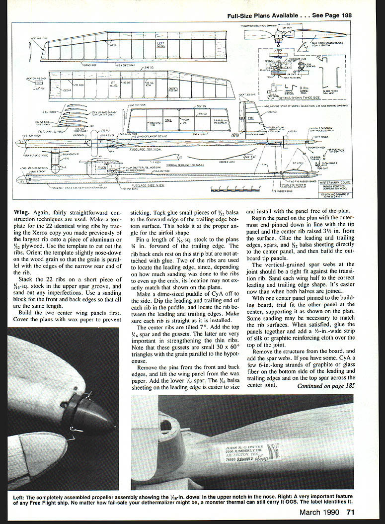
- The Winter Hawk uses a torque-actuated prop stop rather than a tension-sensitive stop. Key features:
- Torque-actuated: lever engages a tack head and stops rotation when motor torque drops to about 1 in./oz., eliminating rubber bunching.
- Allows shorter motor than distance between rear peg and prop shaft hook, preventing unpredictable CG shifts from rubber hunching.
- Short motor reduces chance of prop assembly falling out and losing parts.
- Torque actuation saves altitude by folding the prop while it still pulls; tension-type stops often let the nose drop during the last turns.
- Lever can be engaged prior to mounting the prop to prevent accidental turns during preflight checks; release by rotating the hub slightly backward until a click is heard.
- Proven reliable in Wakefields and Mulvihills with folding props.
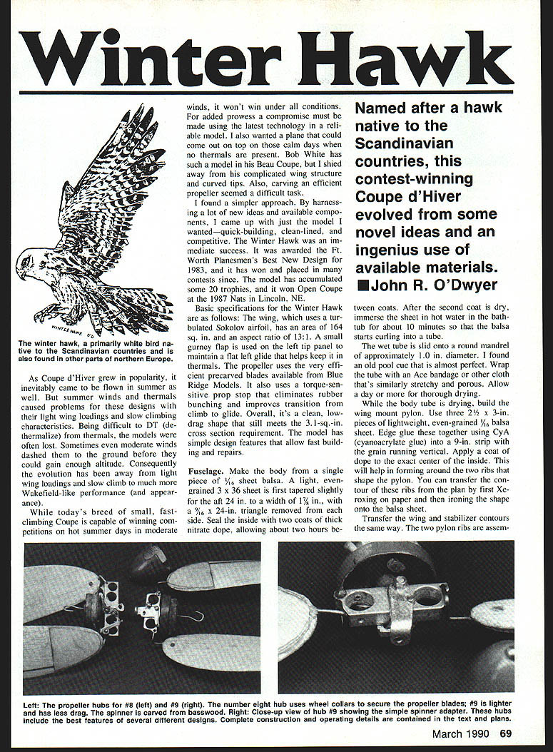
- Hub and mechanism construction
- Obtain an aluminum Coupe hub (e.g., from FAI Model Supply). Turn or cut the hub down to length (about 1/8") to reduce weight and drag as shown on the drawing. Note: plan drawings may be shown at twice actual size; consider copying at half-size as a reference.
- Drill holes with a hand drill, cut with an X-Acto jeweler's saw, and file to shape. The mechanism does not require precision machining and many successful variations exist.
- Blades and attachment
- Form blades with a slight undercamber; the edge with the greater curve is the leading edge. Draw a pencil line from the apex of the inner curve to the center of the tip about 1/32" from the trailing edge at the widest point.
- Locate blade wire on this line 3/32" from the fold pivot. Groove out to accept the wire flush with the surface. Secure the wire with five-minute epoxy and a 1/8" plywood doubler; clamp with clothespins until epoxy sets.
- Blades are held on the hub with small brass washers soldered on the end. If weight allows, 1/8" ID wheel collars may be used for rapid blade replacement.
- Blade area is greatest forward of the wire to place the center of pressure ahead of the elastic axis, so pitch increases under load and reduces as torque decreases. Add a small bead or flanged tip to hold the fold-back pivot.
- Set blade pitch as shown on the drawing; adjust pitch by twisting the wire. Track blades by bending the wire where it acts as a stop against the aluminum hub. A dab of red paint on the blade tip aids visual tracking.
- A spinner reduces drag and protects the hub; if a suitable plastic spinner isn't available, make one from basswood.
Motor, trim, and flying
- Motor installation and winding
- Use a stooge or winder with a torque meter to produce consistent, reliable motor performance.
- Properly tie and secure the rubber motor; ensure hook and retainer allow clean releases for powered and dead-stick flight.
- Trim and test flying
- Trim in calm air using shallow turns and trim for a steady climb. If the model won't thermalize, try adding a small gurney flap to the left tip panel to maintain a flat left glide and help the model fly out of sink.
- Adjust the prop stop and motor runs to optimize climb and transition to glide.
- Balance the model by adding ballast in nose or tail to reach recommended center of gravity.
- Final notes
- The nose and pylon attachments, snuffer tube, and DT sandwich assembly must be secured and installed per the plan.
- The little sandwich assembly at the rear may incorporate a Teflon tube for reduced friction; fit and glue once dry.
- After final covering and dope cure, check alignment and control settings carefully. With careful covering, proper motor preparation, and trimming, the Winter Hawk is a capable Coupe d'Hiver design offering fast construction, easy repairs, and competitive performance.
Complete construction and operating details are contained in the plans. Two bulkheads form short...
Transcribed from original scans by AI. Minor OCR errors may remain.

