
Witch Hawk 500
Background
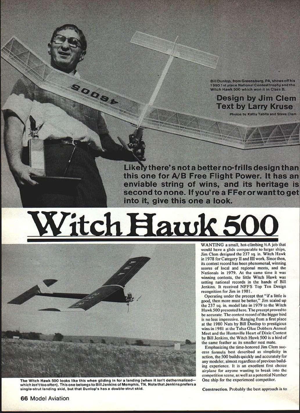
Wanting a small, hot-climbing 1/2A job that would have a glide comparable to larger ships, Jim Clem designed the 237 sq. in. Witch Hawk in 1978 for Category II and III work. Since then its contest record has been phenomenal, winning scores of local and regional meets and the Nationals in 1979. At the same time it was winning contests, the little Witch Hawk was setting national records in the hands of Bill Jenkins. It received NFFS Top Ten Design recognition for Jim in 1981.
Operating under the precept that "if a little is good, then more must be better," Jim scaled up the 237 sq. in. model late in 1979 to the Witch Hawk 500 presented here. The precept proved accurate. The contest record of the bigger bird is no less impressive, ranging from a first place at the 1980 Nats by Bill Dunlop to prestigious wins in 1981 at the Tulsa Glue Dobbers Annual Meet and the Huntsville Heart of Dixie Contest by Bill Jenkins. The Witch Hawk 500 is a bird of the same feather as its smaller nest mate.
Emphasizing Jim Clem’s time-honored success formula best described as simplicity in action, the 500 builds quickly and accurately for any modeler, almost regardless of previous building experience. It is an excellent first-choice airplane for anyone wanting to break into the competition scene, as well as a potential Number One ship for the experienced competitor.
Construction
Preparation and pre-kitting
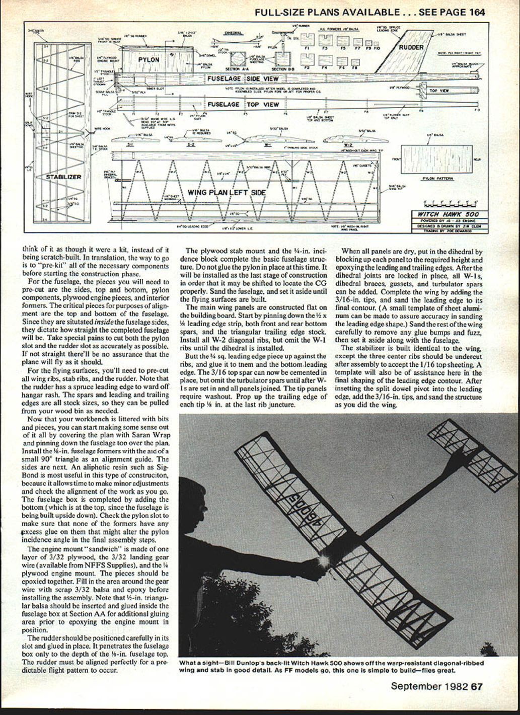
Probably the best approach is to think kit instead of scratch-built. Translation: pre-kit necessary components before starting the construction phase. Prepare fuselage sides, top and bottom sheeting, pylon components, plywood engine pieces, and interior formers — critical pieces for alignment of top and bottom of the fuselage. Since the pylon is situated inside the fuselage, accurate sides dictate that the completed fuselage will be straight.
Take special pains to cut both the pylon slot and rudder slot as accurately as possible; if not straight there will be no assurance the plane will fly. For the flying surfaces you’ll need pre-cut wing ribs, stab ribs and rudder. Note: the rudder has a spruce leading edge to ward off hangar rash. Spars, leading and trailing edges in stock sizes can be pulled from the wood bin as needed.
Fuselage assembly
- Cover the plan with Saran Wrap to prevent glue sticking when pinning parts down.
- Install fuselage formers and sides using a small 90° triangle alignment guide to ensure squareness.
- Use an aliphatic resin such as Sig Bond for assembly; it allows time for minor adjustments and alignment checks.
- Build the fuselage box upside down. After the sides and formers are set, add the bottom and top sheeting.
- Check the pylon slot and ensure no excess glue on formers alters pylon incidence.
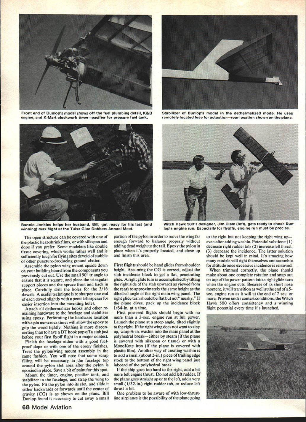
The engine mount sandwich is made of layers of 3/32 plywood. Use landing-gear wire available from NFFS Supplies; epoxy the plywood engine-mount pieces together. Fill the area around the gear wire with scrap 3/32 balsa and epoxy before installing the assembly. Insert triangular balsa and glue it inside the fuselage box as an additional gluing area prior to epoxying the engine-mount position.
Position the rudder carefully in its slot and glue it in place; it penetrates the fuselage box depth. The rudder must be aligned perfectly in the fuselage top for a predictable flight pattern. Add the plywood stab mount and incidence block to complete the basic fuselage structure.
Glue the pylon in place when you are ready; the pylon is typically installed near the last stages of construction. The order may be shifted as necessary. Locate the CG properly, sand the fuselage, and set it aside until the flying surfaces are built.
Wing construction
- Construct main wing panels flat on the building board.
- Pin down the leading-edge strip and both front and rear bottom spars, and the triangular trailing-edge stock.
- Install W-2 diagonal ribs; omit W-1 ribs until dihedral is installed.
- Butt the leading-edge piece up against the ribs and glue them to the bottom leading edge.
- Install the 3/16-in. top spar, but omit the turbulator spars until after W-1s are set in and all panels joined.
- The tip panels require washout: prop up the trailing edge of each tip 1/8 in. at the last rib juncture.
When all panels are dry:
- Put in the dihedral by blocking up each panel to the required height and epoxying the leading and trailing edges.
- After the dihedral joints are locked in place, add all W-1s, dihedral braces, gussets, and turbulator spars.
- Complete the wing by adding the 3/16-in. tips, and sand the leading edge to its final contour. (A small template of sheet aluminum can assure accuracy in sanding the leading edge shape.)
- Sand the rest of the wing carefully to remove any glue bumps and fuzz, then set it aside.
Stabilizer
The stabilizer is built identical to the wing, except:
- After assembly, undercut the three center ribs to accept the 1/16-in. top sheeting.
- Use a template for the final leading-edge contour.
- Insert the split-dowel pivot into the leading edge, add the 3/16-in. tips, and sand the structure as you did the wing.
Covering
The open structure can be covered with plastic heat-shrink films, or with silkspan and dope if preferred. Some modelers like double tissue covering; it works well and is sufficiently tough for flying sites free of stubble or other puncture-producing ground clutter.
Pylon and mount assembly
Assemble the pylon wing mount upside down on your building board from the previously cut components. Use a small 90° triangle to ensure it is square. Place the triangular support pieces and the spruce front and back in place. Carefully drill the holes for the 3/16-in. dowels. A useful technique is to sharpen one end of each dowel slightly with a pencil sharpener for easier insertion into the mounting holes.
Attach all dethermalizer (DT) hooks and other remaining hardware to the fuselage and stabilizer using epoxy. Perforate the hardware location with a pin several times to allow the epoxy to grip the wood tightly.
Finish the fuselage and pylon/wing mount assembly with a good fuel-proof dope or one of the epoxy finishes. Some scrap filling will be necessary in the fuselage top around the pylon slot area after the pylon is epoxied in place — save a bit of paint for this spot.
Final assembly
- Mount the timer, engine, pacifier tank, and stabilizer to the fuselage.
- Strap the wing to the pylon.
- Fit the pylon into its slot and slide it backwards or forwards until the center of gravity (CG) is as shown on the plans.
- If more forward wing location is required to balance without adding tail weight, cut away a small portion of the pylon as Bill Dunlop found necessary.
- Epoxy the pylon in place when properly located and finish this area.
Flying and trimming
Initial flights
- First flights should be hand glides from shoulder height.
- Assuming the CG is correct, adjust the stab incidence block to obtain a flat, penetrating glide.
- A right glide turn is accomplished by tilting the right side of the stab upward (as viewed from the rear) to approximately the same height as the dihedral angle of the right main wing panel. The right glide turn should be flat but not "mushy."
- If the plane dives, pack up the incidence block 1/64 in. at a time.
First powered flights
- Begin with no more than a 3-second engine run at full power.
- Launch the plane at a steep angle, tilted slightly to the right.
- If the right wing does not want to stay up, create wash-in at the polyhedral break by either:
- steaming the wing (if covered with silkspan or tissue), or
- using a MonoKote iron (if covered with plastic film), or
- adding a small (about 2-in.) piece of trailing-edge stock to the bottom of the right wing panel just inboard of the polyhedral break.
- If the ship goes too hard to the right, add a bit more left engine thrust. Do not add left rudder.
- If the plane goes straight up or to the left, add a very small (1/32-in.) right rudder tab, or reduce left thrust a bit.
Low-thrust-line issues
One problem to be aware of with low-thrust-line airplanes is the possibility of the plane going to the right but not keeping the right wing up even after adding wash-in. Potential solutions:
- Decrease right rudder tab.
- Increase left thrust.
- Decrease incidence.
The latter solution is important — many models will right themselves and climb once excessive incidence is removed. When trimmed correctly, the plane should make about one complete rotation and snap out on top of the power pattern into a right glide turn when the engine cuts. Because of its short nose moment, it will transition equally well at the end of a 5-sec. engine run as it will at the end of a 7-sec. or longer.
Proven under contest conditions, the Witch Hawk 500 offers consistency and winning flight potential every time it's launched.
Transcribed from original scans by AI. Minor OCR errors may remain.

