
Wittman D-12 Bonzo
By Frank Beatty
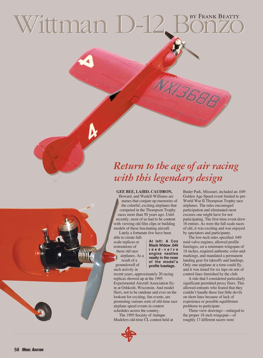
GEE BEE, LAIRD, CAUDRON, Howard, and Wedell-Williams are names that conjure up memories of the colorful, exciting airplanes that competed in the Thompson Trophy races more than 50 years ago. Until recently, most of us had to be content with viewing old film clips or building models of these fascinating aircraft.
Lately a fortunate few have been able to create full-scale replicas or restorations of these old race airplanes. As a result of a groundswell of such activity in recent years, approximately 20 racing replicas showed up at the 1995 Experimental Aircraft Association fly-in at Oshkosh, Wisconsin. And model fliers, not to be outdone and ever on the lookout for exciting, fun events, are promoting various sorts of old-time race airplane speed events in contest schedules across the country.
The 1995 Society of Antique Modelers old-time CL contest held at Buder Park, Missouri, included an .049 Golden Age Speed event limited to pre-World War II Thompson Trophy race airplanes. The rules encouraged participation and eliminated most excuses one might have for not participating. The first-time event drew 16 entries. As were the full-scale races of old, it was exciting and was enjoyed by spectators and participants.
The low-tech rules specified .049 reed-valve engines, allowed profile fuselages, set a minimum wingspan of 18 inches, required authentic color-and-markings, and mandated a permanent landing gear for takeoffs and landings. Only one airplane at a time could fly, and it was timed for six laps on sets of control lines furnished by the club.
A rule that I considered particularly significant permitted proxy fliers. This allowed entrants who feared that they couldn't handle these fast little devils on short lines because of lack of experience or possible equilibrium problems to participate.
Three-view drawings—enlarged to the proper 18-inch wingspan—of roughly 17 different racers were prepared from Lafayette Esquadrille club members' archives and were made available for the asking. Gus Vogele, a dedicated and talented workhorse of the club, handcrafted a perpetual trophy for the event—a Gee Bee Z banking around a checkerboard pylon encased in a protective plastic hood on a handsome base. That was a real incentive for the trophy hounds.
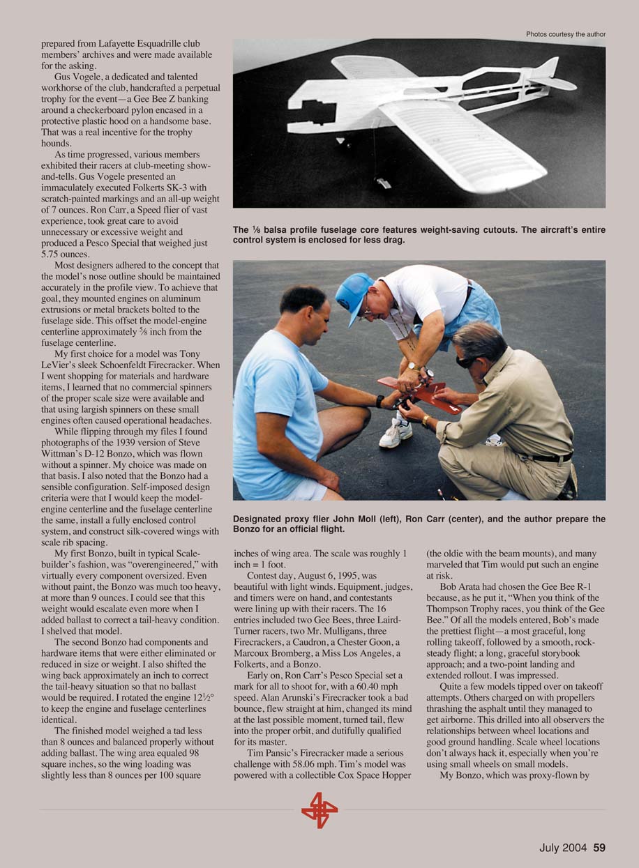
As time progressed, various members exhibited their racers at club-meeting show-and-tells. Gus Vogele presented an immaculately executed Folkerts SK-3 with scratch-painted markings and an all-up weight of 7 ounces. Ron Carr, a Speed flier of vast experience, took great care to avoid unnecessary or excessive weight and produced a Pesco Special that weighed just 5.75 ounces. Most designers adhered to the concept that the model's nose outline should be maintained accurately in the profile view. To achieve that goal, they mounted engines on aluminum extrusions or metal brackets bolted to the fuselage side. This offset the model-engine centerline approximately 5/8 inch from the fuselage centerline.
My first choice for a model was Tony LeVier's sleek Schoenfeldt Firecracker. When I went shopping for materials and hardware items, I learned that no commercial spinners of the proper scale size were available and that using largish spinners on these small engines often caused operational headaches. While flipping through my files I found photographs of the 1939 version of Steve Wittman's D-12 Bonzo, which was flown without a spinner. My choice was made on that basis. I also noted that the Bonzo had a sensible configuration. Self-imposed design criteria were that I would keep the model-engine centerline and the fuselage centerline the same, install a fully enclosed control system, and construct silk-covered wings with scale rib spacing.
My first Bonzo, built in typical scale-builder's fashion, was overengineered, with virtually every component oversized. Even without paint, the Bonzo was much too heavy, at more than 9 ounces. I could see that this weight would escalate even more when I added ballast to correct a tail-heavy condition. I shelved that model.
The second Bonzo had components and hardware items that were either eliminated or reduced in size or weight. I also shifted the wing back approximately an inch to correct the tail-heavy situation so that no ballast would be required. I rotated the engine 12½° to keep the engine and fuselage centerlines identical.
The finished model weighed a tad less than 8 ounces and balanced properly without adding ballast. The wing area equaled 98 square inches, so the wing loading was slightly less than 8 ounces per 100 square inches of wing area. The scale was roughly 1 inch = 1 foot.
Contest day, August 6, 1995, was beautiful with light winds. Equipment, judges, and timers were on hand, and contestants were lining up with their racers. The 16 entries included two Gee Bees, three Laird-Turner racers, two Mr. Mulligans, three Firecrackers, a Caudron, a Chester Goon, a Marcoux Bromberg, a Miss Los Angeles, a Folkerts, and a Bonzo.
Early on, Ron Carr's Pesco Special set a mark for all to shoot for, with a 60.40 mph speed. Alan Arunski's Firecracker took a bad bounce, flew straight at him, changed its mind at the last possible moment, turned tail, flew into the proper orbit, and dutifully qualified for its master.
Tim Pansic's Firecracker made a serious challenge with 58.06 mph. Tim's model was powered with a collectible Cox Space Hopper (the oldie with the beam mounts), and many marveled that Tim would put such an engine at risk.
Bob Arata had chosen the Gee Bee R-1 because, as he put it, "When you think of the Thompson Trophy races, you think of the Gee Bee." Of all the models entered, Bob's made the prettiest flight—a most graceful, long rolling takeoff, followed by a smooth, rock-steady flight; a long, graceful storybook approach; and a two-point landing and extended rollout. I was impressed.
Quite a few models tipped over on takeoff attempts. Others charged on with propellers thrashing the asphalt until they managed to get airborne. This drilled into all observers the relationships between wheel locations and good ground handling. Scale wheel locations don't always hack it, especially when you're using small wheels on small models.
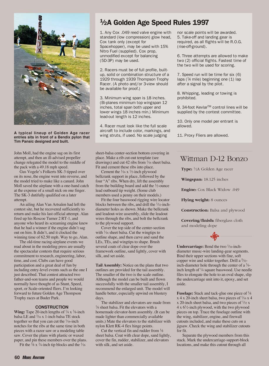
My Bonzo, which was proxy-flown by John Moll, had the engine sag on its first attempt, and then an ill-advised propeller change relegated the model to the middle of the pack with a 49.18 mph speed.
Gus Vogele's Folkerts SK-3 tipped over on its nose, the engine went into reverse, and the model tried to make like a canard. John Moll saved the airplane with a one-hand catch at the expense of a small nick on one finger. The SK-3 dutifully qualified on a later attempt.
An ailing Alan Van Aartsen had left the contest site, but he recovered sufficiently to return and make his last official attempt. Alan fired up his Roscoe Turner 2 RT-1, and anyone who heard its screaming engine knew that he had a winner if the engine didn't sag out on him. It didn't, and it clocked the winning time of 62.50 mph. Way to go, Alan.
The old-time racing-airplane events we read about in the modeling press are usually the spectacular contests that require serious commitment to research, engineering, labor, time, and cost. Clubs can have good participation and a great deal of fun by including entry-level events such as the one I just described. That contest attracted two father-and-son teams and people we would normally have thought of as Stunt, Speed, Sport, or Scale-oriented fliers. I'm looking forward to future Golden Age Thompson Trophy races at Buder Park.
Construction
Wing
- Tape 20-inch lengths of 1/4 x 3/8-inch balsa LE and 1/16 x 1-inch balsa TE stock together so that you can cut the 1/16-inch notches for the ribs at the same time in both pieces with a razor saw or a modeling table saw.
- Cover the plans with plastic or waxed paper, and pin these members in place.
- Fit the 3/8 x 3/4-inch tip blocks and the 1/16 sheet-balsa center-section bottom covering in place.
- Make a rib cut-out template (see drawings) and cut 42 ribs from 1/16 sheet balsa. Fit and cement these ribs into place.
- Cement the 1/16 x 1/2-inch plywood bellcrank support in place, followed by the four "A" ribs. When dry, lift the assembly from the building board and add the 1/2-ounce lead outboard tip weight. (Some club members used a penny on their models.)
- Fit the four basswood rigging wire locator blocks between the ribs, and drill the 1/32-inch-diameter holes as shown.
- Make the bellcrank and leadout-wire assembly, slide the leadout wires through the ribs, and bolt the bellcrank to the plywood support.
- Cover the top side of the center-section with 1/16 sheet balsa.
- Cut the wingtips to outline shape, and then carve and sand the LEs, TEs, and wingtips to shape.
- Brush several coats of clear dope over the framework outline, sand lightly, cover with silk, and set aside.
Tail Assembly
- Notice on the plans that two outlines are provided for the tail assembly. The smaller of the two is the scale outline. Although the model can be built and flown successfully with the smaller tail assembly, I recommend the enlarged unit. The model will handle better, especially upwind on blustery days.
- The stabilizer and elevators are made from 1/8 sheet balsa. Fit the elevators with a homemade elevator-horn assembly (it can be made lighter than commercially available units).
- Mate the elevators to the stabilizer with nylon Kellett RK-4 flex hinge points.
- Cut the vertical fin and rudder from 1/8 sheet balsa. Coat with clear dope, sand lightly, cover with silk, and set aside.
Undercarriage
- Bend the two 1/16-inch-diameter music-wire landing-gear segments.
- Bind their upper sections with fine, soft copper wire and solder together.
- Drill a 5/32-inch-diameter hole through the center of a 3/8-inch length of 1/4 square basswood. Use a short length of music wire to attach the undercarriage unit into it, epoxy, and set aside.
Fuselage
- Stack and tack-glue one piece of 1/8 x 4 x 20-inch sheet balsa, two pieces of 1/16 x 4 x 20-inch sheet balsa, and two pieces of 1/32 x 4 x 20-inch plywood, with the two plywood pieces on top.
- Trace the fuselage outline on the stack and cut out the parts.
- Make the engine bearers from 1/8-inch plywood, install, and cement in place.
- Glue on the 1/16 sheet pieces and sand the fuselage outline smooth.
- Fit the wing saddle and cutouts for the wing and stabilizer. Fit the firewall, install the landing-gear blocks, and cement the nose block in place.
- Use the tail skid mentioned in the plans. Drill the engine bearers per the engine used. File the openings to fit the muffler and tank as shown.
- Separate the plywood members from this stack. Mark the undercarriage-support-block locations, and make this cutout through all three balsa members. Separate the balsa members.
- Take up the 1/8-sheet-balsa core member, mark off the lightening-hole and pushrod-tunnel cutouts, and make those cuts. The rear of the fuselage is now floppy and difficult to maintain in alignment, so cement several 1/8-square balsa stiffeners to span across these cutouts for now.
Final Assembly
- Cut a slot in the wing center-section sheet covering to allow installation and passage for the elevator pushrod.
- Slip the wing and stabilizer just short of their true locations in the fuselage while you eyeball the 1/32-inch-diameter elevator pushrod wire and bend it to size.
- Solder the bellcrank-to-pushrod connection, and then locate and cement the wing to its proper location in the fuselage core member.
- Pass two hardwood guides onto the pushrod, and cement them in their slots. Now you can locate and cement the stabilizer.
- Solder the elevator pushrod-to-horn connection, and check the control system for freedom of movement.
- Cement into position the 1/16-inch fuselage panel on the side opposite the temporary stiffeners. Remove the stiffeners, and cement the remaining panel into position.
- Chamfer the rear edges of the 1/32 plywood fuselage stiffeners, and cement them in place.
- Cut out the 1/4 plywood engine mount.
- You might be satisfied to use wood screws to mount the Cox engine. I used blind mounting nuts. Either will work. Cement the engine mount and balsa fairing blocks into position.
- Epoxy the undercarriage assembly into its slot. Add the vertical fin, rudder, undercarriage strut fairings, and tail skid.
- Drill 1/8-inch-diameter holes and fill them with short lengths of 1/8-inch-diameter birch dowels for the rear rigging wire locators in the fuselage sides.
- Bend and install a wire hoop in the fuselage top at the CG location. You will suspend the model from this point later to determine whether or not it is balanced properly.
- Use a hand-tool burr to gouge clearances for the engine cylinder head and needle valve on the starboard side of the fuselage nose. Also cut a hole in the fuselage nose ahead of the engine cylinder to admit additional cooling air to the engine.
- Mark and drill all 1/32-inch-diameter rigging locating holes in the fuselage, fin, and stabilizer.
Finish
- I covered the fuselage with Sig .56-ounce fiberglass using clear dope as an adhesive.
- Brush the entire model with four coats of clear dope, spray on four coats of filler-coat primer, and spray on six coats of Stearman Red. Wet- or dry-sand (400 grit) these layers after applying every second or third coat.
- Mask off the registration numbers and canopy and spray them black; then mask off and spray the white racing numbers.
- Apply the registration numbers on the fin freehand using a No. 2 Alvin technical pen and India ink, which I protected with a super-thin coat of clear dope.
- Cement silver-doped, half-round dummy exhaust-stack headers to the cowling.
- Use a needle to sew black button thread through the rigging-locator holes. Draw these taut and fix them with cyanoacrylate glue.
- Bend the loops in the leadout-wire ends. According to the contest rules we were using, they must be a minimum of 12 inches from the centerline of the model.
- Solder the wheels on and bolt the engine to the firewall.
- Suspend the completed model from the CG loop. If it does not hang in a slightly nose-down attitude, the model is tail-heavy and will be an unstable flier. Add weight to the nose if this condition exists with your model. The prototype Bonzo assumed roughly a 15° nose-down attitude with no ballast added.
Flying
- Select a calm day and a smooth paved surface for the initial test flight.
- The prototype takes off quickly with little tendency to nose over. The flight pattern is smooth and steady, with little or no fore-and-aft oscillation.
- The model gains a bit of altitude on the upwind side of the circle (normal) and loses a bit more altitude than it gained when it enters the downwind side of the circle—keep that in mind for trimming.
- Landing approaches are long and graceful, but the model does tend to bounce a few times before it settles into its rollout. It is not prone to nosing over or doing the cartwheel bit.
- Using a 5 x 4 Tornado propeller, the Bonzo has been clocked at slightly faster than 56 mph—not too bad for an overweight little beastie that has quite a bit of scale detail built into it.
If you like beautiful models, build the Bonzo as I've described and have fun with it. If you are a speedaholic, put this model on a diet and experiment with fuels and propellers. Tweak the Bonzo just right, and you might have the best of both worlds: looks and speed.
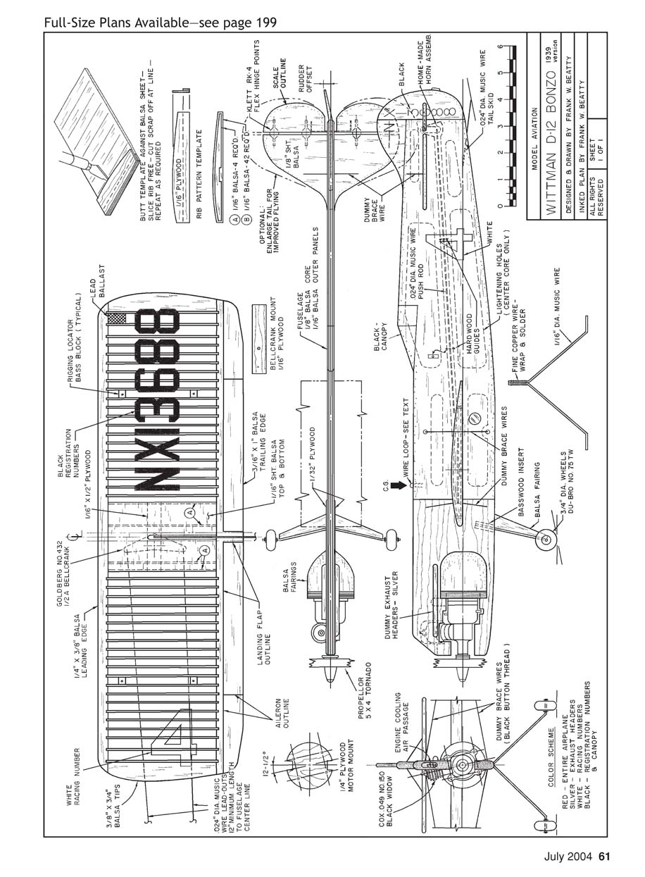
Plan Page
This scanned page contains the full-size plan drawing and diagram labels only.
Frank Beatty 2608 Pontoon Rd. Granite City, IL 62040
Transcribed from original scans by AI. Minor OCR errors may remain.

