
World's Smallest Stits Jr
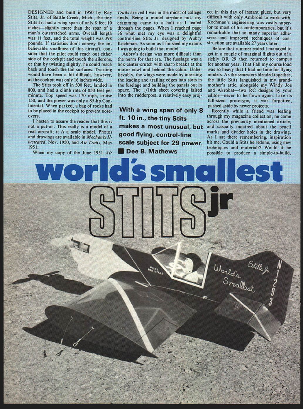
Designed and built in 1950 by Ray Stits, Jr. of Battle Creek, Mich., the tiny Stits Jr. had a wingspan of only 8 ft. 10 in.—slightly more than the span of a man's outstretched arms. Overall length was 11 ft., and the total weight was 398 lb. If statistics don't convey the unbelievable smallness of this aircraft, consider that the pilot could reach out either side of the cockpit and touch the ailerons, or that by twisting slightly he could reach back and touch the tail surfaces. Twisting would have been a bit difficult, however, as the cockpit was only 16 in. wide.
The Stits took off in 500 ft., landed in 800 ft., and had a climb rate of 850 ft./min. Top speed was 170 mph, cruise 150 mph, and the power was only an 85-hp Continental. When parked, a bag of rocks had to be placed in the cockpit to prevent nose-overs.
This is not a put-on. The full-size aircraft really existed; the articles and drawings are in Mechanix Illustrated (Nov. 1950) and Air Trails (May 1951).
Personal background and inspiration
When my copy of the June 1951 Air Trails arrived, I was in the midst of college finals. Being a model-airplane nut, my cramming came to a halt as I leafed through the pages. When I reached page 36 what met my eye was a delightful control-line Stits Jr. designed by Auby Kochman. As soon as I finished my exams I was going to build that model!
"With a wingspan of only 8 ft. 10 in., the tiny Stits makes a most unusual, but good flying, control-line scale subject for .29 power." — Dee B. Mathews
Kochman's design was more difficult than the norm for that era. The fuselage was a box-center-crutch with sharp breaks at the motor cowl and behind the cabin. Unbelievably, the wings were made by inserting the leading and trailing edges into slots in the fuselage and building the panels out in space. The 1/16 in. sheet covering faired into the rudderpost — a relatively easy job in this day of instant glues, but very difficult with only Ambroid to work with. Kochman's engineering was vastly superior to most of his contemporaries, but it's remarkable how many superior adhesives and improved techniques of construction are available decades later.
Before that summer ended I managed a couple of marginal flights with a sickly .29, then returned to campus. The little Stits languished in my grandmother's attic, alongside other models, and was soon forgotten.
Recently, while a friend was leafing through my magazine collection, he came across the article and casually inquired about pencil marks and divider holes in the drawing. Inspiration hit me: could a Stits be redone using new techniques and materials? Could I produce a simple-to-build, good-flying Stits and still retain its unusual appearance? Could prevailing RC practices and hardware be used on a U-control (U.C.) model? Off to the drawing board I went.
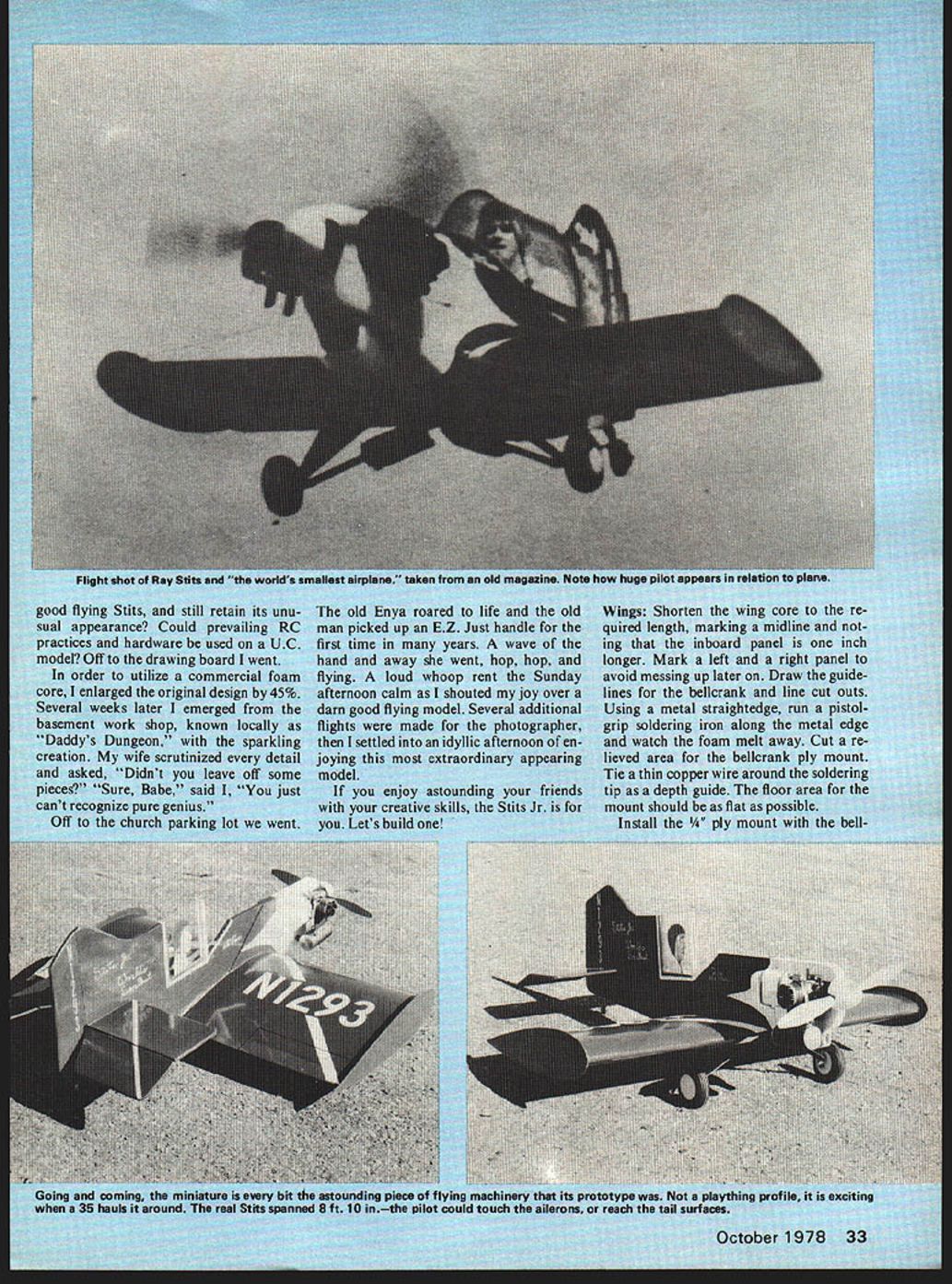
To utilize a commercial foam core I enlarged the original design by 45%. Several weeks later I emerged from the basement workshop, known locally as "Daddy's Dungeon," with the sparkling creation. My wife scrutinized every detail and asked, "Didn't you leave off some pieces?" "Sure, Babe," said I, "You just can't recognize pure genius."
We went to the church parking lot. The old Enya roared to life and the old man picked up an E.Z. just for the first time in many years. A wave of the hand and away she went, hop, hop, and flying. A loud whoop rent the Sunday afternoon calm as I shouted my joy over a darn good flying model. Several additional flights were made for the photographer, then I settled into an idyllic afternoon enjoying this most extraordinary appearing model.
If you enjoy astounding your friends with your creative skills, the Stits Jr. is for you. Let's build one!
---
Parts and Materials
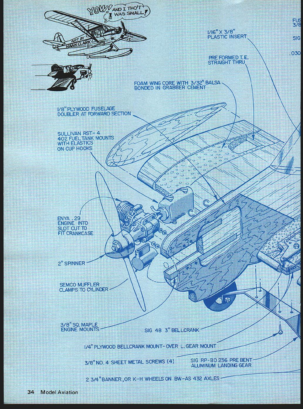
- 1/8" plywood fuselage doubler at forward section
- Foam wing core with 3/32" balsa bonded in Grabber cement
- Sullivan RST-4 (402) fuel tank mounts with elastics on cup hooks
- Enya .29 engine (mounted into a slot cut to fit crankcase)
- 2" spinner
- Semco muffler clamps to cylinder
- 3/8" square maple engine mounts
- Sig 48 3" bellcrank
- 1/4" plywood bellcrank mount (over landing-gear mount)
- 3/8" No. 4 sheet metal screws (4)
- Sig RP-BD 236 pre-bent aluminum landing gear
- 2-3/4" Banner or K-H wheels on BW-AS 432 axles
- 1/16" x 3/8" plastic insert
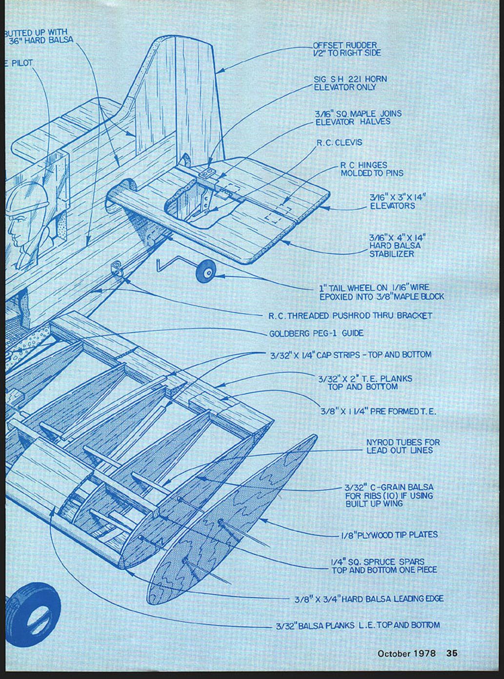
- Pre-formed trailing edge, straight-through, butted up with 3/16" hard balsa
- Pilot (sheet styrene)
- Offset rudder 1/2" to right side
- Sig S H 221 horn (elevator only)
- 3/16" sq. maple joins elevator halves
- RC clevis
- RC hinges molded to pins
- 3/16" x 3" x 14" elevators
- 3/16" x 4" x 14" hard balsa stabilizer
- 1" tail wheel on 1/16" wire epoxied into 3/8" maple block
- RC threaded pushrod through bracket
- Goldberg PEG-1 guide
- 3/32" x 1/4" cap strips (top and bottom)
- 3/32" x 2" T.E. planks (top and bottom)
- 3/8" x 1-1/4" pre-formed T.E.
- Nyrod tubes for leadout lines
- 3/32" C-grain balsa for ribs (10) if using built-up wing
- 1/8" plywood tip plates
- 1/4" sq. spruce spars top and bottom (one piece)
- 3/8" x 3/4" hard balsa leading edge
- 3/32" balsa planks L.E. top and bottom
---
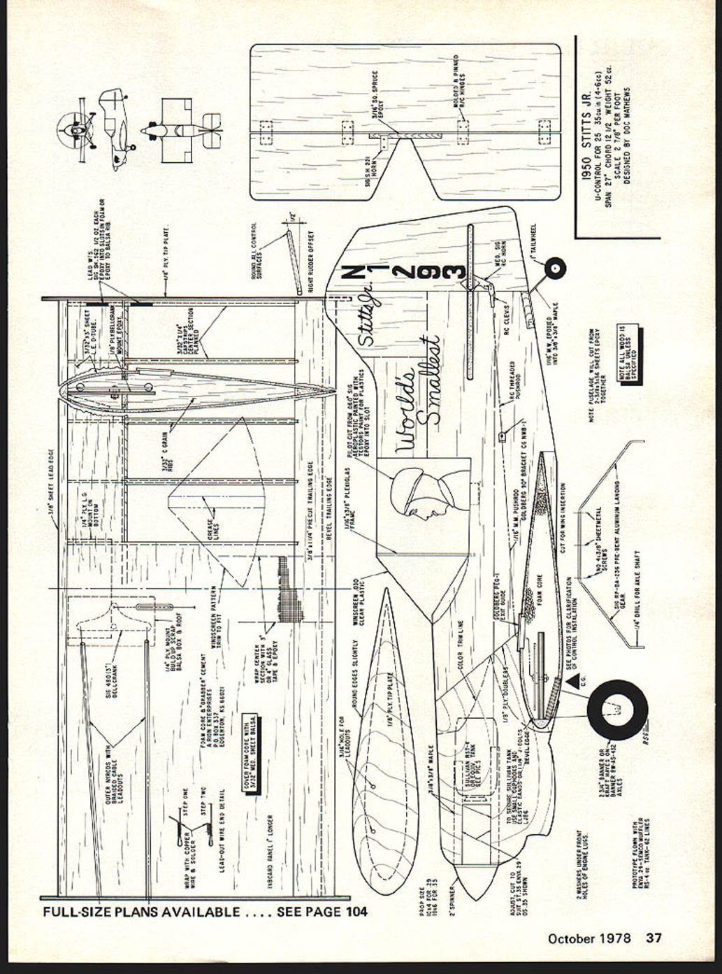
Specifications (1950 Stits Jr.)
- U-control for .25–.35 cu. in. (4.6–5.7 cc)
- Span: 27"
- Chord: 12-1/2"
- Weight: 520 g
- Scale: 2 7/8" per foot
- Designed by: Doc Mathews
---
Building Instructions
Wings
- Shorten the foam wing core to the required length. Mark a midline and note that the inboard panel is 1 in. longer. Mark left and right panels to avoid confusion.
- Draw guide lines for the bellcrank and line cutouts.
- Using a metal straightedge, run a pistol-grip soldering iron along the edge to melt the foam away and cut the openings. Tie a thin copper wire around the soldering tip as a depth guide. Cut a relieved area for the bellcrank ply mount; the floor area for the mount should be as flat as possible.
- Install the 1/4" ply mount with the bellcrank assembly epoxied together. Use weights to keep everything flat on the building surface. Ensure the crank moves freely without binding.
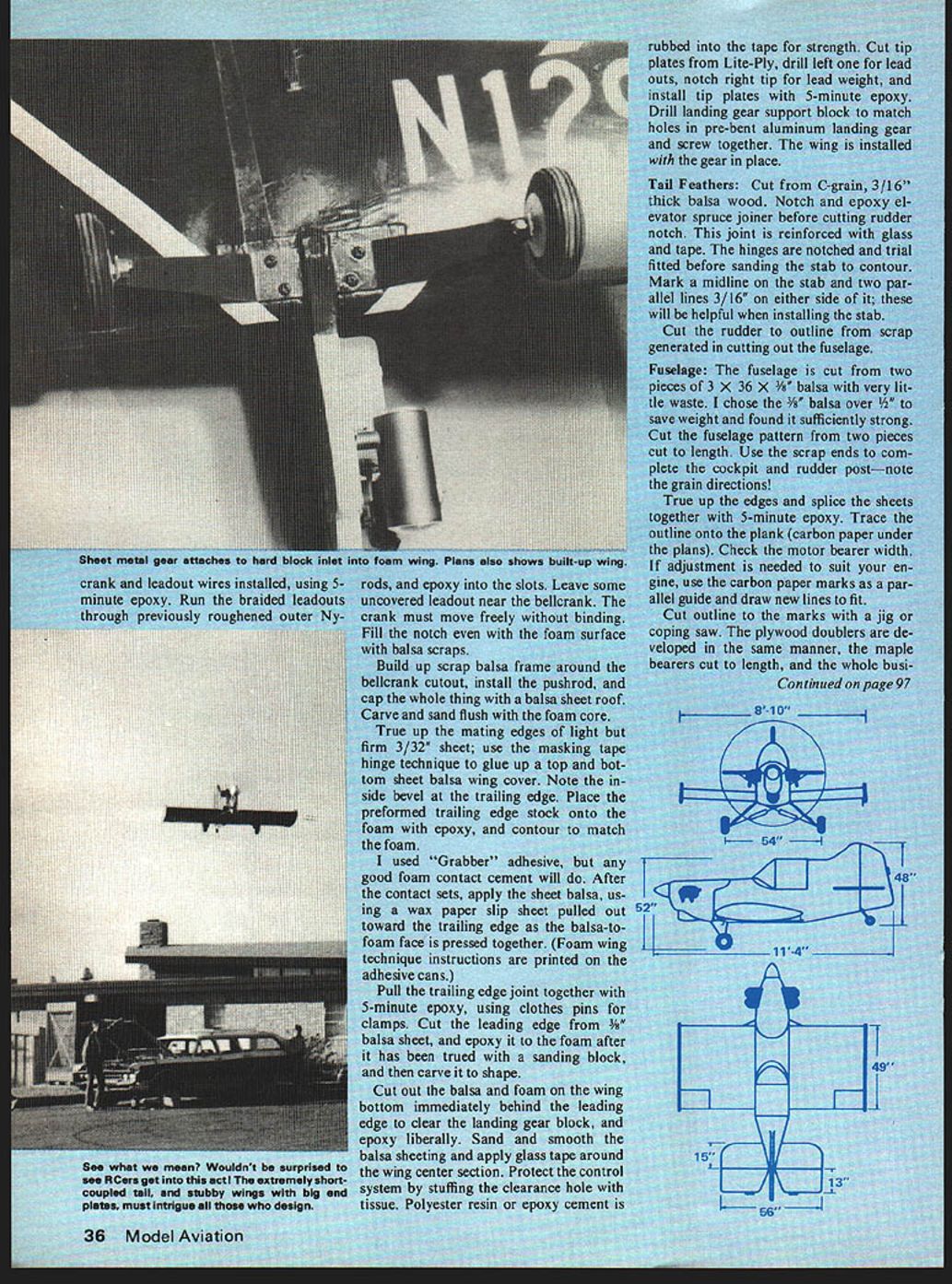
- Crank and leadout wires are installed using 5-minute epoxy. Run the braided leadouts through previously roughened outer Nyrod and epoxy into the slots. Leave some uncovered leadout near the bellcrank.
- Fill the notch even with the foam surface with balsa scraps. Build up a scrap-balsa frame around the bellcrank cutout, install the pushrod, and cap the whole thing with a balsa-sheet roof. Carve and sand flush with the foam core.
True up the mating edges of light but firm 3/32" sheet. Use the masking-tape hinge technique to glue up top and bottom sheet-balsa wing covers; note the inside bevel at the trailing edge. Place the preformed trailing-edge stock onto the foam with epoxy and contour to match the foam.
I used "Grabber" adhesive, but any good foam contact cement will do. After the contact sets, apply the sheet balsa, using a wax-paper slip sheet pulled out toward the trailing edge as the balsa-to-foam face is pressed together. (Foam-wing technique instructions are printed on the adhesive cans.)
Pull the trailing-edge joint together with 5-minute epoxy, using clothespins for clamps. Cut the leading edge from 3/8" balsa sheet, epoxy it to the foam after truing it with a sanding block, then carve it to shape.
Cut out the balsa and foam on the wing bottom immediately behind the leading edge to clear the landing-gear block, and epoxy the block liberally. Sand and smooth the balsa sheeting and apply glass tape around the wing center section. Protect the control system by stuffing the clearance hole with tissue. Rub polyester resin or epoxy into the tape for strength.
Cut tip plates from Lite-Ply. Drill the left tip plate for leadouts, notch the right tip for a lead weight, and install tip plates with 5-minute epoxy. Drill the landing-gear support block to match holes in the pre-bent aluminum landing gear and screw together. Install the wing with the gear in place.
Wing jig
An ordinary paper box can be used as a mating jig. Cut two chord-width slots on opposite sides, measuring equal depth for parallelism. Also cut front and back slots to the fuselage width. The jig will hold the wing level and at right angle.
Tail feathers
- Cut tail surfaces from C-grain, 3/16" thick balsa.
- Notch and epoxy the elevator spruce joiner before cutting the rudder notch. Reinforce this joint with glass and tape.
- Notch and trial-fit the hinges before sanding the stabilizer to contour.
- Mark a midline on the stabilizer and two parallel lines 3/16" on either side; these lines help when installing the stab.
- Cut the rudder to outline from scrap generated in cutting out the fuselage.
- The stab and rudder are not permanently installed until the fuselage is sanded to contour. Tack-glue the rudder in place, sand it to taper, blend into the fuselage rear, then remove it. Epoxy the stabilizer into the slot using the guide lines, then permanently epoxy the rudder on and sand in the offset.
Fuselage
- The fuselage is cut from two pieces of 3" x 36" x 3/8" balsa with very little waste. I chose 3/8" balsa over 1/2" to save weight and found it sufficiently strong.
- Cut the fuselage pattern from two pieces cut to length. Use the scrap ends to complete the cockpit and rudder post—note the grain directions.
- True up the edges and splice the sheets together with 5-minute epoxy. Trace the outline onto the plank (use carbon paper under the plans).
- Check the motor-bearer width. If adjustment is needed to suit your engine, use the carbon-paper marks as a parallel guide and draw new lines to fit.
- Cut the outline to the marks with a jig saw or coping saw. Cut the plywood doublers and maple bearers to length.
- Epoxy the business together (doublers, bearers, and fuselage). Use weights to keep everything flat while curing. After complete curing, drill holes for the engine, tank straps, etc. Epoxy the maple tail-skid block in its notch.
- Adjust the wing cutout and shape the mating wing slot with a wood file and sandpaper. A small piece of rear cutout may need to be removed during fitting and repositioned; then epoxy the wing to the fuselage. Some custom fitting is almost unavoidable since landing gear varies by model.
It is not necessary to completely fill the mating gap; aim for a good solid bite without bubbles or voids. Actual filling of the remainder is better accomplished with a second mix of microballoons and epoxy.
Control system and installation
- Install the powerplant and control system. A nylon horn and snap clevis make an adjustable system.
- Use RC threaded pushrods, RC clevises, and RC hinges as listed in the parts section.
- Install Nyrod tubes for leadouts and run braided leadouts through roughened outer Nyrod, epoxying them into the wing and bellcrank slots.
Pilot and cockpit
- The pilot is cut from sheet styrene, painted with plastic model paint, and epoxied into a slot cut into the balsa. He adds novelty to a profile model.
- Cut a 3/8" wide strip of Plexiglass for the window frame and epoxy it into another slot.
- Make the windshield sections by bending sheet over a scrap of 3/8" balsa, trim to fit, and install with instant glue (Hot Stuff, etc.) or Hold-It R/C-56 glue.
Finish
- The prototype wings were covered with clear Monokote. Wood parts received three coats of clear nitrate dope and two thin coats of K & B Primer, sanded with 380 no-fill paper.
- Protect any areas not to be painted with masking tape. Spray the entire nose section with White Perfect Paint and allow to set for 48 hours, then mask it off while spraying the remainder of the model Perfect Royal Blue.
- Wing numbers were vinyl office-supply items. Rudder numbers from Sig Catalog. Stripes are vinyl trim tape. Other lettering was done with a bow pen and Perfect Paint.
- To hand-letter: dip the drafting pen into a can of paint about 1/4" deep, wipe the exterior off with a tissue, and "write" onto the surface. Practice first to get flow and line width.
---
Flying
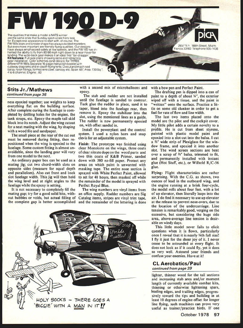
Flight characteristics are rather surprising. With the C.G. as shown, two ounces of lead in the outboard wing, and the engine running briskly on four-cycle, the model rolls about four feet with a lot of up elevator and then literally leaps into the air. It is necessary to use up elevator at release to prevent nose-overs due to the undercarriage location.
Line tension is remarkably good, bordering on excessive, but considering the large side area, above-average line tension is desirable on windy days.
This little model never fails to elicit questions when flown, particularly when you reveal that it is nearly one-quarter full size. I fly it for the sheer joy of it. It does not look as if it could fly, yet it does so very well. Astound your friends and confuse your enemies. Have at it!
Transcribed from original scans by AI. Minor OCR errors may remain.

