
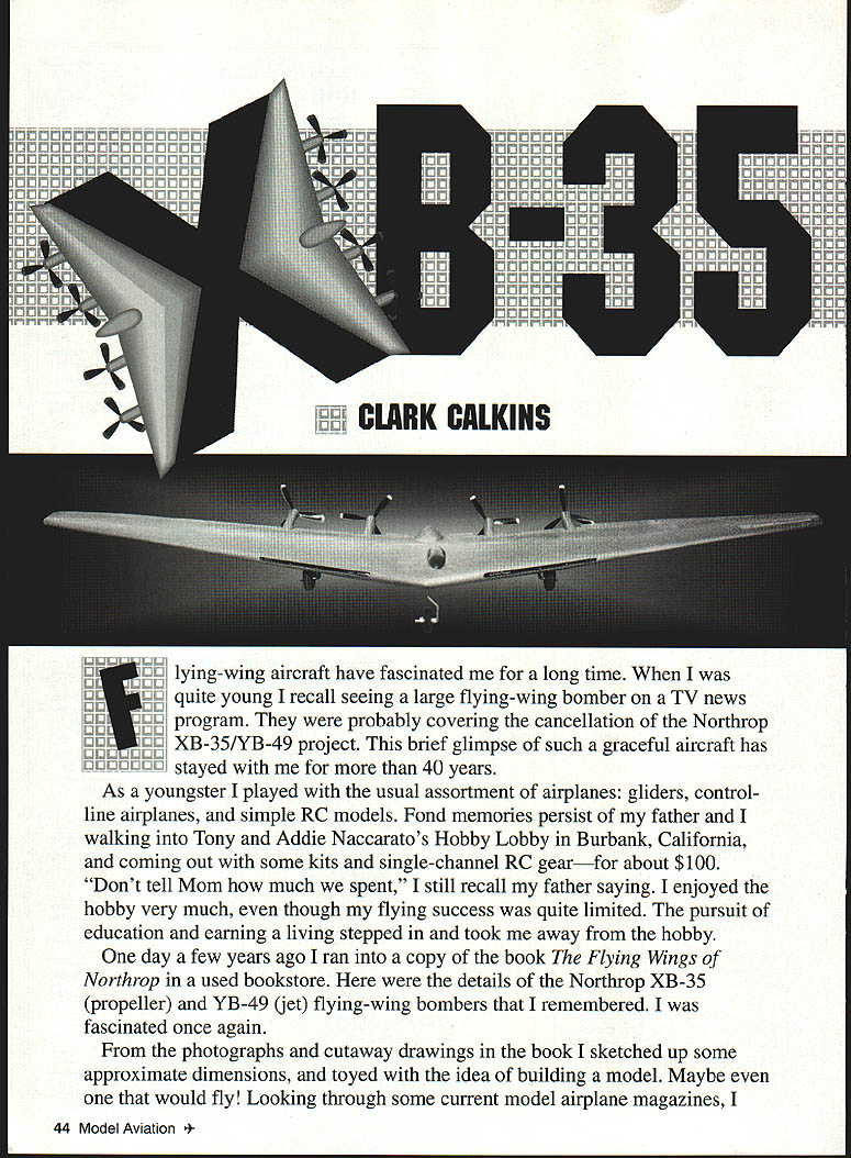
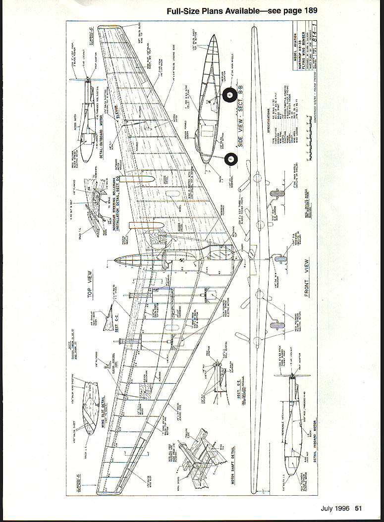
XB-35
Clark Calkins
Flying-wing aircraft have fascinated me for a long time. When I was quite young I recall seeing a large flying‑wing bomber on a TV news program. They were probably covering the cancellation of the Northrop XB‑35/YB‑49 project. This brief glimpse of such a graceful aircraft has stayed with me for more than 40 years.
As a youngster I played with the usual assortment of airplanes: gliders, control‑line airplanes, and simple RC models. Fond memories persist of my father and I walking into Tony and Addie Naccarato's Hobby Lobby in Burbank, California, and coming out with some kits and single‑channel RC gear—for about $100. "Don't tell Mom how much we spent," I still recall my father saying. I enjoyed the hobby very much, even though my flying success was quite limited. The pursuit of education and earning a living stepped in and took me away from the hobby.
One day a few years ago I ran into a copy of the book The Flying Wings of Northrop in a used bookstore. Here were the details of the Northrop XB‑35 (propeller) and YB‑49 (jet) flying‑wing bombers that I remembered. I was fascinated once again.
From the photographs and cutaway drawings in the book I sketched up some approximate dimensions, and toyed with the idea of building a model—maybe even one that would fly! Looking through current model airplane magazines and the literature on flying wings in general and the XB‑35 in particular, I uncovered several excellent publications and was able to determine the basic geometry of the airplane and make good estimates of some less‑obvious parameters.
A 1/2‑scale model would be the smallest practical size that would still have good flying characteristics and could be powered by electric motors. I felt electric power would be easier to control than gas engines. Batteries would provide three to five minutes of flight; power takeoffs would be adequate.
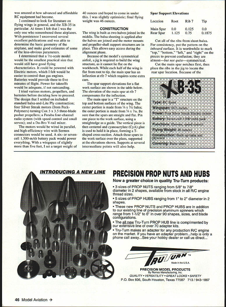
Design summary / Specifications
- Construction: standard balsa-and-LitePly
- Motors: four Silver Streak electric motors (Peck Polymers)
- Propellers: Cox 5 x 3.5 three‑blade pusher propellers
- Radio: Futaba four‑channel system, speed control and small servos
- Mixer: Du‑Bro V‑tail mixer
- Wiring: motors wired in parallel with high‑efficiency wire and servo connectors
- Battery: 6–7 cell, 1,500‑mAh pack
- Wingspan: slightly under 5 ft
- Target weight: 40 oz (final flying weight: 44–48 oz, slightly optimistic at 46 oz)
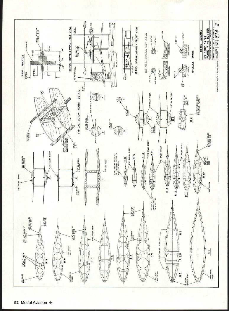
CONSTRUCTION
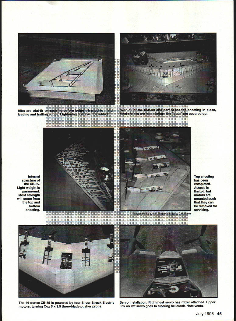
Because the model uses a symmetrical airfoil, a jig is required—the wing structure cannot lie flat on the workbench. The wing is built in two halves and joined in the middle; balsa sheeting is applied after the halves are joined. Motor mounts and propeller‑shaft support structures are placed to allow easy access during the alignment phase.
Spars, ribs and jig setup
- Spar arrangement: main spar is a T‑structure formed from top and bottom members.
- Materials: center portion of the wing uses 2‑lb balsa; the outer portion uses 1/16" sheet balsa.
- Jig: pin pieces to the work surface using a straightedge as a guide. A vertical piece is centered and cyanoacrylate (CyA) glue is used to hold it in place while forming the T cross‑section.
- Ensure the spars are straight and flat. Attach the spars over the plans, supported at the elevations shown below. Intermediate supports are helpful.
Spar support elevations (in inches)
- Main spar: Root 0.000 / Rib 7 0.000 / Tip 0.125
- Rear spar: Root 1.125 / Rib 7 0.750 / Tip 0.1875
- Cut ribs from sheet balsa of consistent thickness; place the pattern on the inboard surface. Mark "top," "bottom," "left," and "right" on pieces to avoid confusion—the wing is almost, but not quite, symmetrical.
- Cut the main‑spar notches first and place the ribs in the jig, locating the rear‑spar position.
- Because of the inflection in the main spar at rib 7, be careful with alignment; a doubler at rib 7 adds strength where the inflection joint appears.
Ribs, leading and trailing edges
- With spar notches in place, remove ribs from the form and trim for the leading and trailing edges; cut lightening holes as required.
- Attach the ribs to the bottom spars. Ribs must be inclined 3° off vertical to compensate for the dihedral angle of the bottom surface.
- Add the top spars once ribs are in place.
- Leading edge: made from 1/4" x 3/4" balsa. Trial‑fit to ensure firm contact with all ribs. Mark top and bottom contact points on each rib, trim excess material, then glue.
- Leading edge includes a large slot for cooling air to reach motors, batteries, and speed control. Cut this slot before attaching the leading edge and trim carefully after gluing.
- Remember the structure is fragile before covering.
Elevons and controls
- Elevons are built from leftover rib balsa. Cover with 1/32" balsa and sand to shape.
- Control horns: 1/8" plywood. Locate hinge points and glue hinges to the elevons first (pin‑point hinges work well).
- Attach elevon hinges to the main wing using thick CyA or epoxy (avoid thin CyA which can wick into hinge joints).
- Elevon throw: ±15° recommended.
- Secure control cables to ribs to reduce slop. Use a Du‑Bro V‑tail mixer for servo mixing as required.
Wing slots and cosmetic details
- Wing slots: no detailed references were found, so straight pieces of 1/32" balsa sheet were glued between ribs for appearance. On the full‑scale XB‑35 these slots were for takeoff and landing only and were closed in normal flight; their effectiveness on a model is uncertain.
Motor mounts and propeller‑shaft supports
- Mounts and housings: built from 1/16" plywood. I used ball bearings with custom propeller adapters for shaft supports; plywood or nylon bearings also work.
- Design motor mounts so motors can be removed for servicing. Align components carefully before final gluing—misalignment causes vibration, loss of power, and fatigue failures.
- Add balsa webbing between the bottom of the propeller shaft supports and the trailing edge to absorb normal vibrations. Do not test‑run motors without this support in place.
Joining wing halves and nacelle
- Join the two wing halves using a 1/8" plywood bulkhead at the main spar for primary strength. Use balsa blocks on top and bottom to fill gaps between bulkhead and spars.
- Verify drillings and fit before gluing. Use slow‑curing epoxy to allow adjustments.
- Secure the two leading edges together with a 1/8" plywood strengthener. A 1/4" plywood rear bulkhead also holds servos—check fit and mixer operation before final assembly.
- Make access hatches for motors, bellcranks, etc. Do not cover these access areas.
- Main nacelle: form shape on wing surface using 1/16" balsa bulkheads and 1/16" square balsa runners. Cover with 1/32" sheet balsa and sand smooth.
Covering and finishing
- Build a simple jig to hold the model firmly at center and wing tips when covering. Each wing incorporates 5° washout (wingtips point down slightly from the front); build washout into the structure before covering—once covered, it cannot be changed.
- Cover material: 1/32" balsa sheet. Start with the leading edge—cover from midpoint of main spar forward. Use thin CyA to hold in place.
- For aft sheeting, glue wider pieces together with thin CyA as needed. Note and leave access hatches uncovered.
- Before both sides are covered, install a dummy antenna wire to pull the real antenna later.
- You may find it easier to install and wire motors before the wing is fully covered, although it can also be done afterward.
- Once covered, remove the model from the jig; it should be very torsionally stiff. Cut two air‑exhaust hatches in the top surface as shown on the plans.
- Make hatch covers from 1/32" balsa and secure with small screws. Use 1/32" wide strips of 1/32" balsa to cover propeller shaft housings; light filler may be used if necessary.
- Sand smooth and paint with silver automotive trim paint—use minimal paint to control weight.
- Pilot's canopy: vacuum‑form a plastic canopy over a carved wooden block, paint with canopy black, and attach with plastic cement. Add a small pilot head if desired.
Landing gear
- Main gear: 3/32" music wire.
- Nose gear: 1/16" music wire with steerable nose‑wheel support formed from 3/16" plywood; drill a 1/16" hole for the wire.
- If you lack a wire bender, form the gear using two door‑hinge pins held in a vise.
- Use Sullivan SkyLite wheels or similar. If necessary, install small trailing "training wheels" from the wingtips to help prevent tipping on rough runways.
FINAL INSTALLATION, BALANCE, AND FLYING
- Servo installation: the rightmost servo has the mixer attached. The upper link from the left servo can go to the steering bellcrank.
- Motors are mounted for limited access; top sheeting may restrict access—plan wiring and servicing accordingly.
Center of gravity (CG)
- Check CG carefully—location should be very close to the plans. Start with CG slightly ahead (not more than 1/4") of the plans' location.
- Move batteries to adjust CG; avoid adding dead weight if possible.
- Target final flying weight: about 44–48 oz.
Flight notes and handling
- A smooth runway helps prevent bouncing—the nose is light.
- Taxi tests: check steering; slight misalignment of main gear makes ground control difficult.
- Throttle behavior: at speed, sudden throttle reduction can cause the nose to lift (propeller thrust exerts downforce on the nose wheel at high power).
- Initial flight trim: batteries fully charged (peak charge preferred), trim elevons up about 3°. For first flights, close off wing slots with clear plastic tape to reduce drag and improve acceleration.
- Takeoff: into wind, full throttle should get airborne in ~100 ft. You may need a bit of up elevator to leave the ground.
- Climb gradually as speed builds—model is not overpowered.
- Turns: be cautious and turn slowly until familiar—the symmetrical airfoil and low dihedral will not self‑right quickly after a turn.
- After ~30 seconds, cut power to conserve batteries and keep the model close to maintain orientation.
- Landings: with light wing loading the model tends to float; decelerates when power is cut due to large propeller area. Land under power for better control.
The sight and sound of this model in the air is amazing. It sure brought back memories!
Clark Calkins 1907 Alvarado Ave. Walnut Creek, CA 94596
References
- Kohn, Leo J. The Flying Wings of Northrop, 1974.
- Maloney, Edward T. Northrop Flying Wings, 1975.
- Wooldridge, E.T. Winged Wonders: The Story of the Flying Wings, 1983.
TWITT ("The Wing Is The Thing") — Tailless aircraft group: Box 20430, El Cajon, CA 92021
Transcribed from original scans by AI. Minor OCR errors may remain.

