
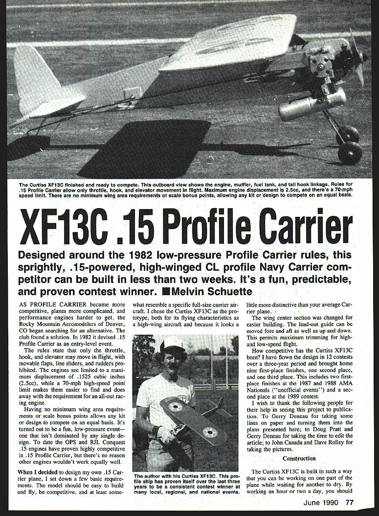
XF13C .15 Profile Carrier
Designed around the 1982 low-pressure Profile Carrier rules, this sprightly, .15-powered, high-winged CL profile Navy Carrier competitor can be built in less than two weeks. It's a fun, predictable, and proven contest winner. — Melvin Schuette
As Profile Carrier became more competitive, planes more complicated, and performance engines harder to get, the Rocky Mountain Aeromodelers of Denver, CO began searching for an alternative. The club found a solution. In 1982 it devised .15 Profile Carrier as an entry-level event.
The rules state that only the throttle, hook, and elevator may move in flight, with movable flaps, line sliders, and rudders prohibited. Engines are limited to a maximum displacement of .1525 cubic inches (2.5 cc), while a 70-mph high-speed point limit makes them easier to find and does away with the requirement for an all-out racing engine.
Having no minimum wing area requirements or scale bonus points allows any kit or design to compete on an equal basis. It's turned out to be a fun, low-pressure event—one that isn't dominated by any single design.
To date the OPS and RJL Conquest .15 engines have proven highly competitive in .15 Profile Carrier, but there's no reason other engines wouldn't work equally well.
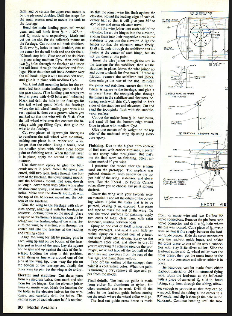
When I decided to design my own .15 Carrier plane, I set down a few basic requirements. The model should be easy to build and fly, be competitive, and at least somewhat resemble a specific full-size carrier aircraft. I chose the Curtiss XF13C as the prototype, both for its flying characteristics as a high-wing aircraft and because it looks a little more distinctive than your average carrier plane.
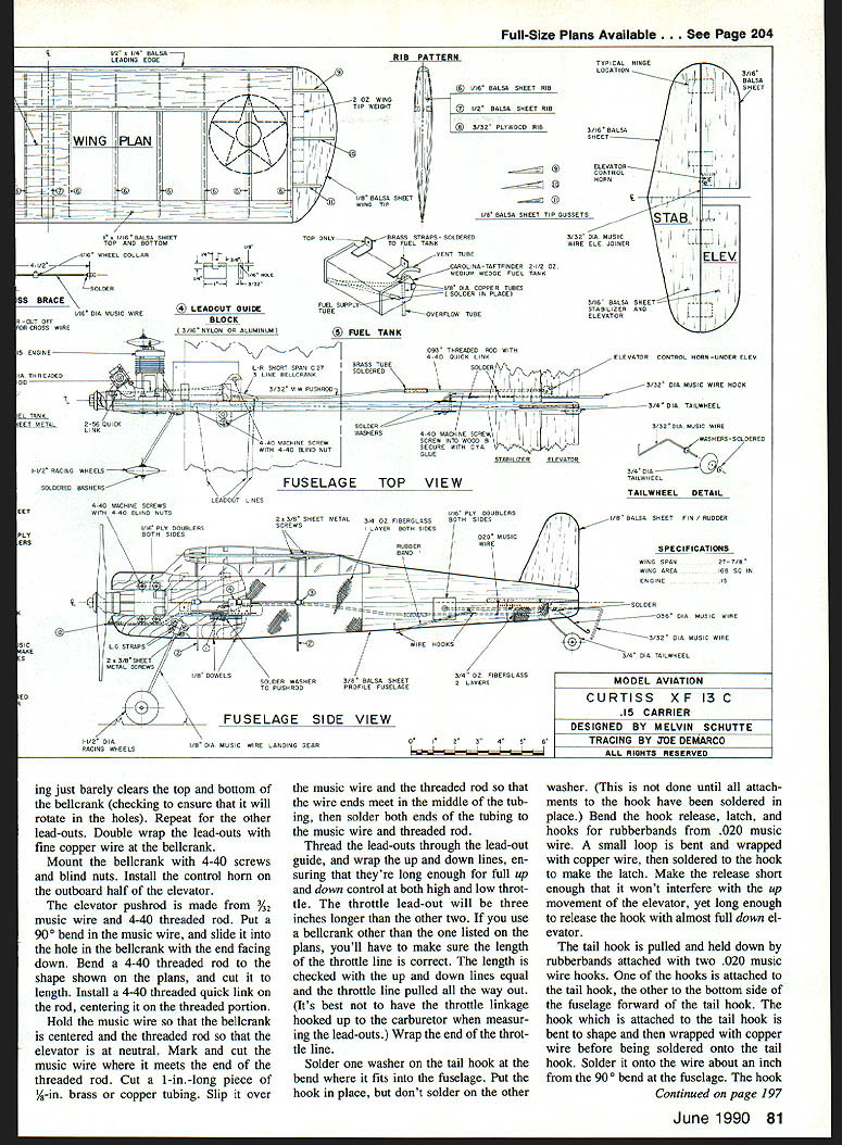
The wing center section was changed for easier building. The lead-out guide can be moved fore and aft as well as up and down. This permits maximum trimming for high- and low-speed flight.
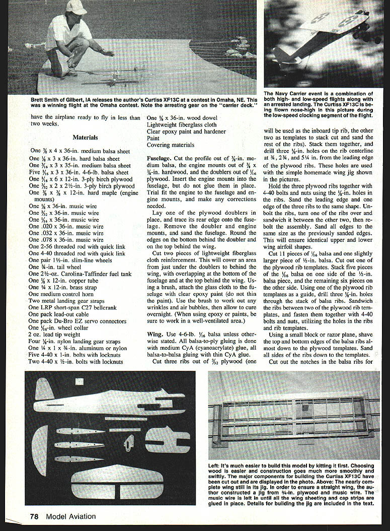
How competitive has the Curtiss XF13C been? I have flown the design in 12 contests over a three-year period and brought home nine first-place finishes, one second place, and one third place. This includes two first-place finishes at the 1987 and 1988 AMA Nationals ("unofficial events") and a second place at the 1989 contest.
I wish to thank the following people for their help in seeing this project to publication: Gerry Deneau for taking some lines on paper and turning them into plans; Doug Pratt and Gerry Deneau for taking time to edit the article; and John Canada and Dave Rolley for taking the pictures.
Construction
The Curtiss XF13C is built in such a way that you can be working on one part of the plane while waiting for another to dry. By working an hour or two a day, you should be able to finish the plane in less than two weeks.
Materials
- One 3/8 x 4 x 36-in. medium balsa sheet
- One 1/8 x 3 x 36-in. hard balsa sheet
- One 1/16 x 3 x 35-in. medium balsa sheet
- Five 1/16 x 3 x 36-in. 4-6-lb. balsa sheets
- One 1/16 x 6 x 12-in. 3-ply birch plywood
- One 3/32 x 2-1/2-in. 3-ply birch plywood
- One 3/8 x 3/4 x 12-in. hard maple (engine mounts)
- One 1/8 x 36-in. music wire
- One 3/32 x 36-in. music wire
- One 1/16 x 36-in. music wire
- One .020 x 36-in. music wire
- One .032 x 36-in. music wire
- One .078 x 36-in. music wire
- One 2-56 threaded rod with quick link
- One 4-40 threaded rod with quick link
- One pair 1-1/2-in. slim-line wheels
- One 3/8-in. tail wheel
- One 2-1/2-oz. Carolina-Taffinder fuel tank
- One 1/2 x 12-in. copper tube
- One 1/4 x 12-in. brass strap
- One medium control horn
- Two metal landing gear straps
- One LRP short-span C27 bellcrank pack
- One pack lead-out cable
- One pack Du-Bro EZ servo connectors
- One 1/16-in. wheel collar
- 2 oz. lead tip weight
- Four 3/8-in. nylon landing gear straps
- One 1/4 x 1 3/4-in. aluminum or nylon (part)
- Five 4-40 x 1-in. bolts with locknuts
- Two 4-40 x 1/2-in. bolts with locknuts
- One 1/4 x 36-in. wood dowel
- Lightweight fiberglass cloth
- Clear epoxy paint and hardener
- Paint
- Covering materials
Fuselage
Cut the profile out of 3/8-in. medium balsa, the engine mounts out of 3/8 x 3/4-in. hardwood, and the doublers out of 1/16 plywood. Insert the engine mounts into the fuselage, but do not glue them in place. Trial-fit the engine to the fuselage and engine mounts, and make any corrections needed.
Lay one of the plywood doublers in place, and trace its rear edge onto the fuselage. Remove the doubler and engine mounts, and sand the fuselage. Round the edges on the bottom behind the doubler and on the top behind the wing.
Cut two pieces of lightweight fiberglass cloth reinforcement. This will cover an area from just under the doublers to behind the wing, with overlapping at the bottom of the fuselage and at the top behind the wing. Using a brush, attach the glass cloth to the fuselage with clear epoxy paint (do not thin the paint). Use the brush to work out any wrinkles and air bubbles, then allow to cure overnight. (When using epoxy or paints, be sure to work in a well-ventilated area.)
Wing
Use 4-6-lb., 1/8-in. balsa unless otherwise stated. All balsa-to-ply gluing is done with medium CyA (cyanoacrylate) glue; all balsa-to-balsa gluing with thin CyA glue.
Cut three ribs out of 3/32 plywood (one will be used as the inboard tip rib, the other two as templates to stack-cut and sand the rest of the ribs). Stack them together, and drill three 1/8-in. holes on the rib centerline at 3/8, 2-3/4, and 5-1/4 in. from the leading edge of the plywood ribs. These holes are used to speed the assembly of the wing jig.
Hold the three plywood ribs together with 4-40 bolts and nuts using the 1/8-in. holes in the ribs. Sand the leading edge and one edge of the three ribs to the same shape. Unbolt the ribs, turn one of the ribs over and sandwich it between the other two, then re-bolt the assembly. Sand all edges to the same size as the previously sanded edges. This will ensure identical upper and lower airfoil shapes.
Cut 11 pieces of 1/16 balsa and one slightly larger piece of 1/8-in. balsa. Cut out one of the plywood rib templates. Stack five pieces of the 1/16 balsa on one side and the remaining six pieces on the other side. Using one of the plywood rib templates as a guide, drill three 1/8-in. holes through the stack of balsa ribs. Sandwich the ribs between two of the plywood rib templates, and fasten them together with 4-40 bolts and nuts, utilizing the holes in the ribs and rib templates.
Using a small block or razor plane, shave the top and bottom edges of the balsa ribs almost down to the plywood templates. Sand all sides of the ribs down to the templates. Cut out the notches in the balsa ribs for the 3/8-sq. balsa wing spars with an X-Acto saw and knife. Cut the two 3/16-sq. wing spars and the 1/4-in. triangular leading edge to length. Mark the wing rib locations on one of the wing spars and the leading edge.
Remove the bolts and plywood templates from the stack of ribs. Use one of the inboard plywood ribs on the side of the stack which has only five ribs on one side of the center rib. Insert three 1/8 x 36-in. music wires through the holes in the ribs, spacing the ribs along the wire. Support the wires at the same height at both ends and the center of the wing. Support all the wires at the ends, and the front and rear wires in the center, until the leading edge sheeting is installed; then support the center and rear wires.
Square up the two tip ribs with the leading edge and one edge of the wing spars, and glue them in place. Align and glue the rest of the ribs.
Cut two 1/16 x 1-in. balsa trailing edges to length, and mark 1/8 in. from the same edge at both ends of one of the trailing edge pieces. Place the marked piece of trailing edge sheeting on the bottom edge of the ribs with the marks touching the trailing edge of the ribs at each end of the wing. Affix the ribs to the trailing edge sheet, gluing the ends first.
Turn the wing over. Place a bead of medium CyA on the last 1/8 in. of the trailing edges of the ribs, and along the aft 1/8 in. of the trailing edge sheeting already in place. Position the other sheet, lining up the edges. Rub the sheeting at the ribs and along the trailing edge as the glue is drying.
Cut the wing center section sheeting, and attach it with medium CyA. Cut wing cap strips to length from 1/16 x 1/4-in. balsa. Glue the cap strips to each rib as follows:
- Place a bead of medium CyA along the edge of the rib, put the cap strip in place, and apply a drop of CyA glue at both its ends.
- Note that the outboard edges of the cap strips on the tip ribs line up with the outboard edge of the ribs, while the rest are centered on the ribs.
Remove the 3/32-in. wires from the wing. Using a small block plane, shave the leading edge to rough shape, then finish sand to final shape. Cut a sheet of lightweight fiberglass cloth equal to the width of the wing center section sheeting, and wrap it around the front of the center section. Apply the glass cloth by brushing on clear epoxy paint. Work out any wrinkles or air bubbles.
Fuselage/wing, other major assembly
Lightly sand the entire fuselage. Attach one of the 1/8-in. plywood doublers with slow-cure epoxy, spreading the glue lightly over the part before setting it in place. Epoxy all engine mounts and the sides of the upper and lower engine mounts, and attach. Glue in the other doubler in the same manner.
Wrap the fuselage from behind the doublers to over the nose of the plane with clear plastic sandwich wrap. Place this assembly between two pieces of 1/4-in. or thicker plywood, and clamp it carefully with C-clamps. After checking to ensure that the doublers are still in the proper position, allow it to dry overnight.
The tank is a modified 2-1/2-oz. wedge type. To ensure that there is plenty of fuel at the pickup tube during low speed, the V part of the tank is mounted toward the fuselage. Make the tank tubing out of annealed 1/8-in. copper tubing. The fuel pickup tube is cut off at a 45° angle and soldered to the rear, lower outboard corner of the tank, 1/8 in. from the rear wall. The pickup tube extends to the top center of the tank front. Solder the vent tube to the top of the pickup tube in front of the end. The vent tube exits the top front of the tank to the inside of the rear of the fuel pickup tube, pointed forward into the airstream.
The overflow tube is soldered into the out-front outboard corner of the tank and exits the bottom front. This tube is plugged during flight.
Solder three pieces of brass strap to the tank for mounting to the fuselage. Solder one of the straps to the lower rear of the tank for mounting to the fuselage. Drill the straps for the small screws used to mount the tank to the fuselage.
Bend the main landing gear, tail wheel gear, and tail hook from 5/32-in., .078-in., and 3/32-in. music wire respectively. Mark and cut out the slot for the bellcrank mount on the fuselage. Cut out the tail hook doublers. Drill two 3/32-in. holes in each doubler, one at the center for the tail hook and one for the 4-40 hook stop tab. Glue one of the doublers in place using medium CyA, then drill the two 3/32-in. holes through the fuselage and insert the tail hook through the doubler and fuselage. Place the other tail hook doubler over the tail hook, align it with the stop hole, and glue it in place with medium CyA.
Mark and drill mounting holes for the engine, fuel tank, main landing gear, and landing gear straps. (The landing gear straps are held in place with 4-40 bolts and locknuts.)
Mark and drill the hole in the fuselage for the tail wheel gear. Mark the fuselage where the tail wheel landing gear wire is to rest against it, then cut a groove where you marked so that the wire will fit flush. Coat the tail wheel wire area that contacts the fuselage with gap-filling CyA, then glue the wire to the fuselage.
Cut two pieces of lightweight fiberglass to reinforce the tail wheel wire mounting, making one piece 1/2 in. wider and 1/4 in. longer than the other. Using a brush, coat the smaller piece with either clear epoxy paint or finishing resin. When the first layer is in place, apply the second in the same manner.
Use slow-cure epoxy to glue the bellcrank mount in place. When the epoxy has cured, drill two 1/16-in. holes through the bottom of the fuselage, the lower engine mount, and the bellcrank mount. Cut 1/8-in. dowels to length, cover them with either white glue or slow-cure epoxy, and insert them into the holes. Make sure the dowels are flush with the top of the bellcrank mount and the bottom of the fuselage.
Glue the wing to the fuselage with slow-cure epoxy, aligning it with the fuselage as follows: looking down on the model, place a square or draftsman's triangle along the fuselage and the trailing edge of the wing. Secure the wing by inserting pins through the center and into the fuselage at the leading and trailing edges.
Align the wing for tilt by putting pins in each wing tip and on the bottom of the fuselage just in front of the spar. Lay the square on the spar and up against the side of the fuselage. Holding the wing in this position, wrap string or fine wire around one of the pins at the wing tip, then wrap the pin on the bottom of the fuselage and finally the other wing tip pin. Set the wing aside to dry.
Elevator and stabilizer
Cut these parts from 5/16-in. medium balsa, then mark and slot them for the hinges. Cut the elevator joiner from 3/32-in. music wire. Mark the location for the holes in the elevator halves for the wire joiner, and carefully drill the holes. The leading edge of each elevator half is notched so that the joiner wire fits flush against the elevator. Round the leading edge of each elevator half so that it will give you 35° to 45° of up and down elevator travel.
Insert the wire joiner into each half of the elevator. Insert the hinges into the elevator, sliding them into their respective slots in the stabilizer to position the elevator. Align the hinges so that the elevators move freely. Drill a 1/8-in. hole through the stabilizer and elevator at the center of each hinge, but do not pin them at this point.
Insert the wire joiner through the slot in the fuselage for the stabilizer, then set the stabilizer in place. Move the wire joiner up and down to check for free travel. If there is any friction, remove the stabilizer and joiner, then enlarge the rear of the slot. Reinstall the joiner and stabilizer, ensure the stabilizer is square to the fuselage, and glue in place. Insert toothpick pins through the hinges in the stabilizer and elevators, and set them, curing each with thin CyA applied to both sides of the stabilizer and elevators. Cut and sand the toothpicks flush with the stabilizer surface.
Cut out the rudder from 5/16-in. hard balsa, and sand all but the bottom edge round. Glue in place with medium CyA.
Glue two ounces of tip weight on the top side of the outboard wing tip using slow-cure epoxy.
Finishing
Due to the higher nitro content of fuel used with carrier airplanes, the author prefers to use epoxy paint throughout. But that's not the final word on finishing — select another method if you wish.
The model was patterned after the scheme used on the prototype: painted aluminum, with yellow on the upper half of the wing, stabilizer, and elevators. The liberal .15 Profile Carrier rules allow you to choose any paint scheme desired.
Cover the wing with your favorite iron-on material. Tape off the edges of the covering where it joins the balsa that is to be painted, leaving 4 in. exposed. Use paper and tape to mask the rest of the wing. To seal the wood surfaces for painting, apply two coats of K&B clear paint with satin hardener, sanding between coats.
Spray on one coat of K&B primer, allow to dry overnight, and sand it until little remains. Spray on a second coat of primer, and sand lightly after drying. Spray on the aluminum color coat, and allow to dry. If adopting the scheme used on the prototype, mask and tape off the top half of the stabilizer and elevators from the rest of the fuselage, and paint them yellow.
Tape off the outline of the canopy, then paint it a contrasting color. When the paint is thoroughly dry, remove all tape and paper from the model.
Final details
The lead-out guide is made from either 3/16-in. aluminum or nylon, but other materials can be used. Drill all the holes in the lead-out guide before cutting out the notch where the wheel collar will go. The lead-out guide cross brace is made from 1/8-in. music wire and two Du-Bro EZ servo connectors. Remove the pin from each servo connector and drill a 1/16-in. hole where the pin was located. Cut a piece of 1/16-in. music wire so that it fits snugly between the lead-out guide braces. Slide the servo connectors over the lead-out guide brace and solder the cross brace to one of the servo connectors with silver solder. Slide the lead-out guide over the cross brace, then put the cross brace in the other servo connector and silver solder it in place.
The lead-outs can be made from either lead-out material or .018-in. stranded flying wire. Bush the lead-outs at the bellcrank with a piece of annealed 1/8 x 1/2-in. brass tubing, slip them through the tubing, allowing enough to protrude so that they can be wrapped. Bend the tubing at the center to a 90° angle, and slip it through the hole in the bellcrank. Continue bending until the tubing is in place; it should just barely clear the top and bottom of the bellcrank (check to ensure that it will rotate in the holes). Repeat for the other lead-outs. Double-wrap the lead-outs with fine copper wire at the bellcrank.
Mount the bellcrank with 4-40 screws and blind nuts. Install the control horn on the outboard half of the elevator.
The elevator pushrod is made from 3/32-in. music wire and 4-40 threaded rod. Put a 90° bend in the music wire, and slide it into the hole in the bellcrank with the end facing down. Bend a 4-40 threaded rod to the shape shown on the plans, and cut it to length. Install a 4-40 threaded quick link onto the rod, centering it on the threaded portion.
Hold the music wire so that the bellcrank is centered and the threaded rod so that the elevator is at neutral. Mark and cut the music wire where it meets the end of the threaded rod. Cut a 1-in. long piece of 1/8-in. brass or copper tubing. Slip it over the music wire and the threaded rod so that the wire ends meet in the middle of the tubing, then solder both ends of the tubing to the music wire and threaded rod.
Thread the lead-outs through the lead-out guide, and wrap the up and down lines, ensuring that they're long enough for full up and down control at both high and low throttle. The throttle lead-out will be three inches longer than the other two. If you use a bellcrank other than the one listed on the plans, you'll have to make sure the length of the throttle line is correct. The length is checked with the up and down lines equal and the throttle line pulled all the way out. (It's best not to have the throttle linkage hooked up to the carburetor when measuring the lead-outs.) Wrap the end of the throttle line.
Solder one washer on the tail hook at the bend where it fits into the fuselage (this is not done until all attachments to the hook have been soldered in place). Bend the hook release, latch, and hooks for rubberbands from .020-in. music wire. A small loop is bent and wrapped with copper wire, then soldered to the hook to make the latch. Make the release short enough that it won't interfere with the movement of the elevator, yet long enough to release the hook with almost full down elevator.
The tail hook is pulled and held down by rubberbands attached with two .020-in. music wire hooks. One of the hooks is attached to the tail hook, the other to the bottom side of the fuselage forward of the tail hook. The hook which is attached to the tail hook is bent to shape and then wrapped with copper wire before being soldered onto the tail hook. Solder it onto the wire about an inch from the 90° bend at the fuselage. The hook on the bottom of the fuselage for rubberbands is positioned forward of the tail hook so that there is tension on the rubberband with the hook down. (Use small rubberbands.)
Insert the tail hook through the doublers, and solder a washer to it on the opposite side of the fuselage.
Apply a drop of medium CyA in the tail hook doubler stop-holes in the doublers to harden them. Screw a 4-40 bolt through these holes. The screw enters from the hook side, passes through the fuselage, and ends flush with the outside edge of the doubler on the other side.
Use #2 x 3/16-in. screws to mount the fuel tank to the fuselage.
Mount the main landing gear, then lock it in place with 1/8-in. nylon landing gear straps and 4-40 bolts and nuts.
Use Glenn Lee 1/2-in.-dia. racing wheels or a similar type. Solder the inside washer onto the landing gear axle, and slip on the wheel. Put a small piece of sandpaper, a little larger than the washers used, over the landing gear wire, and solder the outside washer onto the wire. Remove the sandpaper from between the washer and wheel. Repeat for the other wheel.
To help smooth out the throttle response during low-speed flight, the throttle arm is lengthened so that full movement of the bellcrank is required to fully open the carburetor. Remove the throttle arm from the carburetor. Cut a 1/2-in.-long piece of 3/32-in. brass tubing, and flatten it to fit over the throttle arm. Sand or file off any anodizing on the throttle arm where the extension will be soldered. Place the flattened tubing over the throttle arm, and continue flattening until it's tight against the throttle arm. Solder the throttle arm extension in place, then reassemble the carburetor and connect the throttle linkage. Drill a 1/8-in. hole 5/8 in. from the end. (The length of the extension may vary with the carburetor used.)
Mount the engine with 4-40 bolts and locknuts. Insert a washer between the bolt heads and engine mounting lugs, and another between the doubler and locknuts.
The throttle linkage is made from 2-56 threaded rod. Bend the rod to shape and install a threaded quick link so that it is centered on the threaded portion of the rod. Attach the linkage to the carburetor throttle arm. Install a solder quick link on the throttle arm of the bellcrank. Ensure that the bellcrank and carburetor are in the high-speed position. (If you use the bellcrank shown on the plans, pull all the way out on the up-and-down lead-outs.) Position the threaded rod against the solder link, and cut it to length (it should protrude about 1/16 in.). Solder the threaded rod into the quick link.
Using the lead-outs, work the throttle linkage to ensure free throttle movement. Work the elevator to ensure that it moves freely in both high and low speeds as well as in midrange.
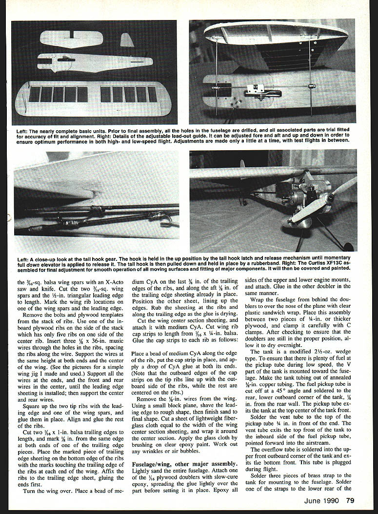
Flying
Start with the lead-out guide 2½ in. from the bottom of the wing and 1½ in. from the front lead-out guide brace. Trim the plane for high speed by moving the lead-out guide forward or back until the plane is as close to 70 mph as you can get it (25.7 seconds for eight laps).
Trim the plane for low speed by moving the lead-out guide either forward or back, and either up or down.
Make adjustments to the lead-out guide one at a time, moving the guide just a little each time. Fly the plane before making further adjustments.
No matter how workmanlike your building, nothing can take the place of practice in learning to handle a particular model. Fly the aircraft in all kinds of weather; you'll be ready for anything on contest day.
If you have any questions about building or flying the Curtiss XF13C, feel free to contact Melvin Schuette at P.O. Box 240, Auburn, KS 66402, or through CompuServe's ModelNet addressed to 73170,2741.
Transcribed from original scans by AI. Minor OCR errors may remain.

