
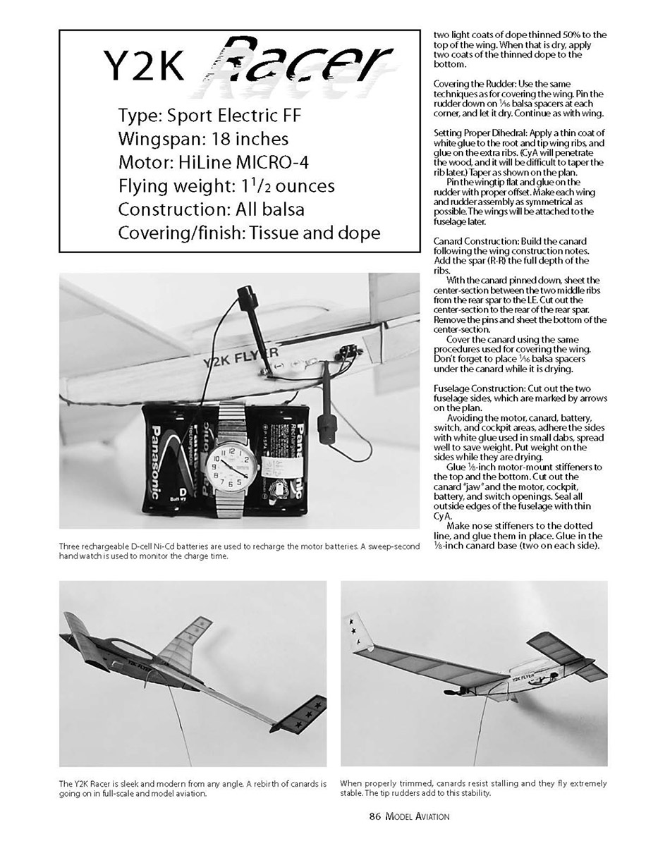
Y2K Racer
by Charles Fries
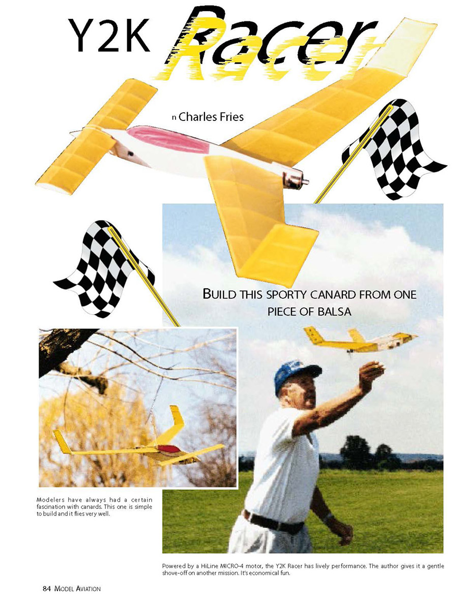
BUILD THIS SPORTY CANARD FROM ONE PIECE OF BALSA
This little Electric Free Flight model is similar to the Thistle featured in the February 1995 Model Aviation. It started out with three objectives: that it be built using one piece of 1/16- x 3- x 36-inch piece of balsa; that it look like a modern aircraft; and, above all, that it be a good, consistent flier. All objectives were met after more than a year of trial and error. Designing the model was easy, and building it and aligning the surfaces went smoothly. The rub was getting the airplane to fly in a consistent manner, but the result was very satisfying.
CONSTRUCTION
Why the emphasis on one piece of balsa? I have built a number of aircraft from plans, and they all call for a wide variety of materials and sizes; I have my shop well stocked. But what about the guy just starting out? It must be discouraging. Hence fewer people build their own models, and they miss the thrill of seeing their creations fly. In contrast, I have selected readily available materials, such as ordinary gift-wrapping tissue and a glue stick for covering materials. Instant glue (CyA, or cyanoacrylate) is available at local stores. No special tools are needed; a single-edge razor blade should suffice. I heartily recommend that a starting builder’s first tool be a balsa stripper, such as the one available from Master Airscrew. The power plant can be purchased as a complete unit from several sources. I have the MICRO-4 I bought several years ago from HiLine for the Thistle. A complete unit is preferable to shopping around for some special part that is hard to find.
This little model is not the traditional "floater" glider. Positioning the canard allows it to be flown straight ahead or in circles. I have flown mine five feet off the ground in 100-foot circles, and 100 feet high straight ahead. (Not recommended unless you like to walk!)
Wings and Rudders
- Lay wax paper over the plans.
- Pin the 3/16-inch leading edge (LE) and trailing edge (TE) from wing rib 1 to rudder rib D.
- Notch the wing ribs for the LE and TE.
- Using a minimum of CyA, glue the LE and TE in place.
- Leave roughly a 1/16-inch space beyond wing rib 5, and glue in the rudder ribs.
Refer to the drawing of the wing-root profile and glue the 1/8-inch LE vertically against the bottom LE and the ribs (adhere from the inside). Use a straightedge to mark the location of the spar on each rib. Notch the ribs and glue in the spar. Lightly coat the entire spar with thin CyA for strength. Separate the wing from the rudder, as indicated. Round the LE of the wing and the rudder. Lightly coat the LE and the TE with thin CyA.
Covering the Wing
- Using a permanent-type glue stick, apply tissue to the top and bottom of the wing (the shiny side of the tissue is up).
- Lightly mist the tissue with water, and pin the LE and the root down on wax paper.
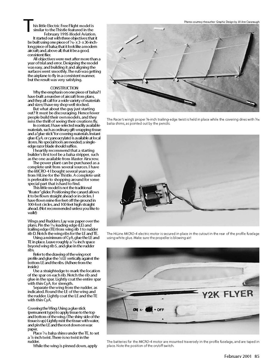
- Place 1/16-inch balsa shims under the TE to set a 1/4-inch twist. (There is no twist in the rudder.)
- While the wing is pinned down, apply two light coats of dope thinned 50% to the top of the wing. When that is dry, apply two coats of the thinned dope to the bottom.
Covering the Rudder
Use the same techniques as for covering the wing. Pin the rudder down on 1/16-inch balsa spacers at each corner and let it dry. Continue as with the wing.
Setting Proper Dihedral
Apply a thin coat of white glue to the root and tip wing ribs, and glue on the extra ribs (CyA will penetrate the wood and make later tapering difficult). Taper as shown on the plan.
Pin the wingtip flat and glue on the rudder with the proper offset. Make each wing and rudder assembly as symmetrical as possible. The wings will be attached to the fuselage later.
Canard Construction
Build the canard following the wing construction notes. Add the spar (R–R) the full depth of the ribs.
With the canard pinned down, sheet the center section between the two middle ribs from the rear spar to the LE. Cut out the center section to the rear of the rear spar. Remove the pins and sheet the bottom of the center section.
Cover the canard using the same procedures used for covering the wing. Place 1/16-inch balsa spacers under the canard while it is drying.
Fuselage Construction
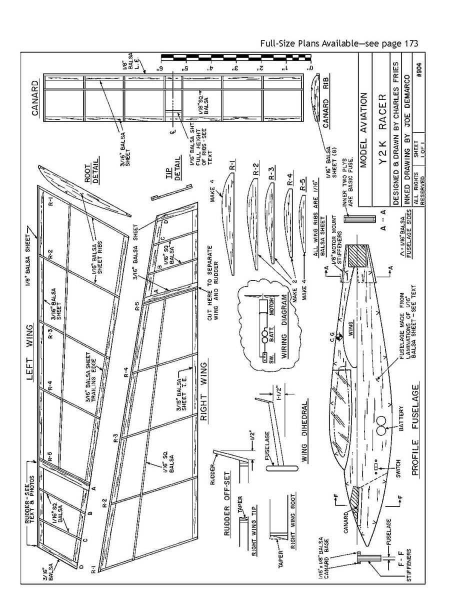
- Cut out the two fuselage sides, which are marked by arrows on the plan.
- Avoiding the motor, canard, battery, switch, and cockpit areas, adhere the sides with white glue in small dabs, spread well to save weight. Put weight on the sides while they are drying.
- Glue 1/8-inch motor-mount stiffeners to the top and the bottom.
- Cut out the canard "jaw" and the motor, cockpit, battery, and switch openings.
- Seal all outside edges of the fuselage with thin CyA.
- Make nose stiffeners to the dotted line, and glue them in place.
- Glue in the 1/8-inch canard base (two on each side).
Final Assembly
- Block up the fuselage vertically.
- Temporarily put one wing on the fuselage centerline and check for 1½ inches of dihedral. Glue the wing to the fuselage when you are certain the proper dihedral and wing alignment are present.
- Carefully position the other wing, check for symmetry in dihedral and alignment, and glue the wing to the fuselage when things look perfect.
- Glue the motor-area stiffeners to each side of the fuselage, covering the 1/16-inch strip already on the top and bottom of this area.
- Apply two coats of thinned dope to the fuselage. Colored dope is heavier; the secret to this model is keeping it light. Each prototype weighed about 12 ounces.
- Customize the airplane to your liking with a marking pen.
Mounting Motor and Prop
- Line up the propeller shaft with the centerline (bottom of the wing).
- Apply white glue to the top and the bottom of the motor in the cutout area with care, and mount it in the cutout area. (If you use CyA it may seep into the motor.)
- The HiLine MICRO-4 electric motor is secured in place in the cutout in the rear of the profile fuselage using white glue. Make sure the propeller is blowing air!
- The batteries for the MICRO-4 motor are mounted transversely in the profile fuselage and are taped in place. Note the position of the on/off switch.
- Position the batteries and hold them in place with Scotch tape. Wire the units together.
- Make sure the propeller is blowing air backward and that the motor is spinning in the correct direction.
Balancing the Model
- Poke a hole through the center of gravity (CG) location. Bend a paper clip to support the model and check forward/aft balance. It is best if the model balances roughly 5° nose-down to help prevent porpoising.
- Drive a pin a short distance into the nose. Check the lateral balance by supporting the model with the propeller and the pin. One wing will be heavier; apply a weight on the opposite wing at the juncture of the wing and rudder to balance it.
Flying
- Attach the canard with two small rubber bands.
- Find a field with high weeds for initial tests and conduct them on a calm day.
- Give the Racer approximately five seconds of charge and throw it straight ahead, as you would throw a dart at a board five feet away. (Not with a wrist snap, but with a follow-through.)
- If the model zooms, add minimum weight to the nose. If the model dives, add weight to the motor area. In either case, make sure the canard is on squarely. The canard angle is at the optimum as shown on the plans.
- After you have sorted things out with short flights, gradually increase the charge for longer flights. Then start experimenting with changes in the canard position.
With care and patience, you will be rewarded with many fine flights.
— Charles Fries 1114 Charles St. Mechanicsburg, PA 17055
Transcribed from original scans by AI. Minor OCR errors may remain.

